Page 44 of 2189
Lift and Support Points
Floor Jack
Apply the parking brake and block the wheets thatare not being lifted.
When lifting the rear of the vehicle, put the gearshiftlever in reverse (Automatic transmission/Cw in Eposition).
Raise the vehicle high enough to insert the safetystands.
Adjust and place the safety stands so the vehiclewill be approxlmately level, then lower the vehicleonto them.
FRONT:
Always use safety stands whon working on or undelany vehicle that is supported by only a iack.Never attempt to use a bumper jack for lifting orsupporting the vehicle.
t,1.
REAR:
1-42
LIFT PLA
4.
Center the jacking
bracket in the middleof the iack lift platform.
Center the iackbracket in the middleof the jack lift ptatform.
-,-_
LIFT PLATFORM
L,
Page 96 of 2189

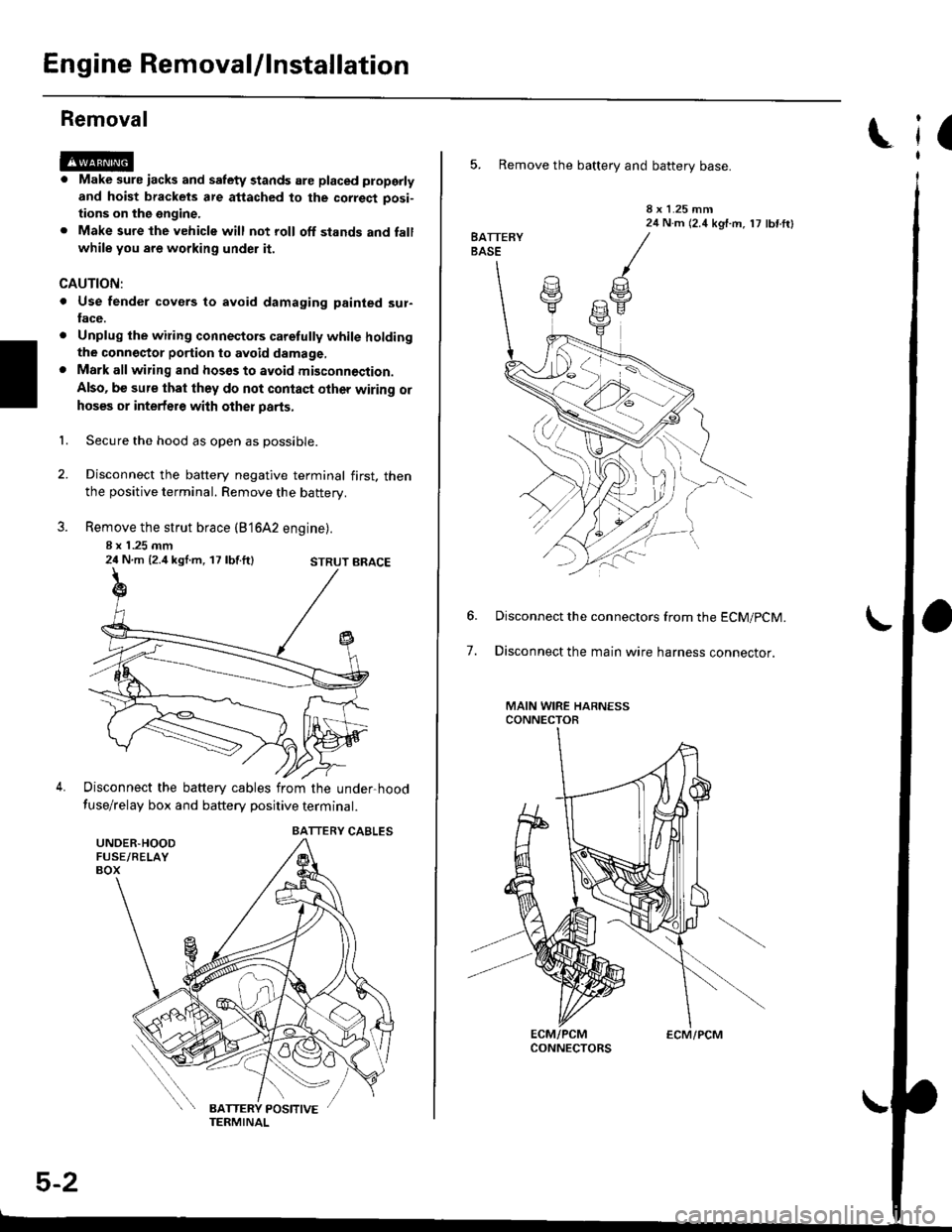
Engine RemovaUlnstallation
Removal
@@
1.
. Make sure iacks and salety stands are placed ploperly
and hoist brackets are attached to the correct posi-
tions on the engine.
. Make sure the vehicle will not roll off stands and fall
while you are working under it.
CAUTION:
. Use fender covers to avoid damaging painted sur-face.
. Unplug the wilin9 connectors caretully while holdingthe conngstor portion to avoid damage,. Mark all wiring and hosos to avoid misconnoction.
Also, be sure that they do not contact other wiring or
hoses or interfere with other parts,
Secure the hood as open as possible.
Disconnect the battery negative terminal first. thenthe positive terminal. Remove the battery.
Remove the strut brace (B'16A2 engine).
8 x 1 .25 mm24 N.m {2.4 kgl.m, 17 lbf.ft}
Disconnect the battery cables from the under-hood
fuse/relay box and battery positive terminal.
STRUT BRACE
UNDER.HOODFUSE/RELAYBOX
BATTERY CABLES
5-2
ECM/PCM
(
5. Remove the battery and battery base.
8 x 1.25 mm24 N.m (2.4 kgf.m, 17 lbf ftl
7.
Disconnect the connectors from the ECM/pCM.
Disconnect the main wire harness connector.
MAIN WIRE HARNESSCONNECTOR
Page 104 of 2189
Engine RemovaUlnstallation
Removal(cont'd)
38. Attach the chain hoist to the engine.
HOISTING BRACKETInstall on the cylinder headwitha8x1.25mmbolt.
5-10
Page 105 of 2189
39. Remove the left and right front mount and bracket'
MOUNT/BRACKET
40. Remove the rear mount bracket.
41. Remove the uPPsr bracket.
42. Remove the transmission mount bracket, then
remove the transmission mount.
44.
Check that the engine/transmission is completely
free of vacuum hoses, fuel and coolant hoses and
electricalwiring.
Slowly raise the engine approximately 150 mm (6 in)'
Check once again that all hoses and wires are discon-
nected from the engine^ransmission
Raise the engine all the way, and remove it from the
car.
UPPER
TRANSMISSION
45.
5-11
Page 106 of 2189
Engine RemovaUlnstallation
Installation
Brackei Bolts Torque Specifications:
Dl5Y5, Dl6Y7, Dl6Y8 €nginss
D16Y5, D16Y8 engines (M/Tl:
REAR STIFFENER
8 x 1.25 mm2/t N.m 12.4 kgf.m, 17 tbf.ftl
EXCEPT D16Y5, Dl6Yg engines lM/T)jSTIFFENERTighten the bolts on the stiffenerin the numbered sequence as shown
10 x 1.25 mm44 N.m 14.5 kgf.m,33 tbf.frt
O8x1.25mm24 N.m {2.4 kg{.m,17 tbr.ftt
10 x 1.25 mm14 N.m 14.5 kgt m,33 tbf.ft)
10 x 1.25 mm44 N.m {4.5 kgt m,33 tbr.ftl
10 x 1.25 mm54 N.m {5.5 kgf.m,40 rbf.ftl
10 x 1.25 mm44 N.m {4.5 kg'f.m,33 tbtftlALTERNATOFBRACKET
li) o).
l3l 10 x 1.25 mm44 N.m {1.5 kgt.m,33 tbt.ft)8 x 1.25 mm24 N.m (2.4 kgf.m,17 tbf.ft)
o16Ys, D16Y8enginoslM/T):FRONTSTIFFENER
10 x 1.25 mm4,4 N.m {4.5 kg{.m.33 tbf.ftl8 x 1.25 mm2{ N.m (2.t kgtm,17 rbtft)
10 x 1.25 mm14 N.m (4.5 kgf.m,33 lbf.ftl
5-12
Page 107 of 2189
816A2 engine
P/S PUMPBRACKET
REARSTIFFENER
SIDE ENGINEMOUNT BRACKET
t0 x 1.25 mmia{ N.m (i1.5 kgt rn,
33 lbt.tr)
t
12 x 1.25 nm57 N.m {5.8 kgf,m,12 tbl.ttl
8 x 1.25 mm24 N.m (2.4 kgl.m,17lbf.ft)
FRONTSTIFFENER
A/C COMPBESSORBRACKET
10 x 1.25 mm54 N m {5.5 kgf m, a0 lbl ft}
10 x 1.25 mm4a N,m (4.5 kgf.m,33 tbf.ftt
ALTERNATORBRACKET
'12 x 1.25 mm
57 N.m {5.8 kgt'm,
42 tbt.ft)8 x 1.25 mm24 N.m {2.4 kgf.m,17 tbtft)
'10 x 1.25 mm,14 N.m {,1.5 kgt.m,33 rbf.ft)
(cont'd)
5-13
Page 108 of 2189
Engine Removal/lnstallation
Installation (cont'd)
Engino Inst!llation:
Install the engine in the reverse order of removal.Beinstall the mount bolts/nuts in the following sequence.Failure to follow these procedures may cause excessivenois€ and vibration, and reduce bushing life.
l, Install the transmission mount and bracket, thentighten the bolts on the frame side,
NOTE; Do not tighten the bolts/nuts on the trans_mission side.
CW;
10 x 1.25 mm38 N.m {3.9 kgt m. 28 lbt.ftl
5-14
I
I
2, Install the upper bracket, then tighten the nuts inthe numbered ssquence shown (O _ @).
l'
aO t2 x 1.25 mm74 N.m 17.5 kgf.m,O t2 x t.2s mm74 N.m 17.5 kgtm,rbrft)
Page 109 of 2189
3. Install the rear mount bracket, then tighten the bolts
in the numbered sequence shown (O - @).
CVT:
O 12 x 1.25 mm59 N.m (6.0 kgl'm,ilil lbf ftlReplace.
12 x 1.25 mm59 N.m 16.0 kgf'm,|:r tbf.tt)Replace.
O 12 x 1.25 mm59 N'm {6.0 kgf'm,/€ lbf.ftlReplace.
Except CVT:
,@ 14 x'1.5 mm
/ 8:t N.m {8.5 kgf.m,
/ 61 rbr.fr) Replace.
O 12 r 1.25 mm
59 N m 16.0 kgt m,(} tbf.fttReplace.
Olax1.5mm83 N.m 18.5 kgf.m,61 tbf.ftlReplace.
L
4. Tighten the bolvnuts on the transmission mount
bracket in the numbe.ed sequence shown (O - O).
@ t2 x t.2s mm7,1N.m (7.5 kg{ m, 54 lbf ftl
Tighten the bolts on the right front mounvbracket in
the numbered sequence shown (O - @).
GW:
O to x 1.25 mm54 N.m {5.5 kgl.m./|{} lbf.ftl
10 x 1.25 mm4,1 N.m {4.5 kgf.m. 33 lbf.ftl
(cont'd)
5-15
12 x 1,25 mmfl N.m 16.5 kgt.m,47 tbf.ftl