Page 1720 of 2189
Gruise Control
Actuator Disassembly
ACTUAYOR CABLE
0
o
ACTUATOR BRACKET
WIRE SUPPORT BRACKET
ACTUATORTest, page 23 245
SOLENOID VAI-VESTest, page 23 247
SOLENOIDSEAL
I
+*RlAC
E
23-250
Page 1806 of 2189
Airbag
Replacement (cont'd)
Front Passenger's Side:
. Remove the three mounting nuts from the bracket,then remove the harngss clip.. Lift the front passenger's airbag out of the dashboardby covering the lid and dashboard with a cloth, andprying carefully with a flat-tip screwdflver.
NOTE: The lid of the airbag has pawls on its sidewhich attach it to the dashboard.
24-6a
CAUTION: B€ sure to inslall the SRS wiring so that it isnot pinched or interforirg with other parts.
4. Installthe new airbag(s):
Driver's Side: Place the driver,s airbag into the steeringwheel, and secure it with new Torx botrs.
TORX BOLTS9.E N.m (1,0 kgf.m, 7.2 tbt ftlReplace.
Front Pass€ngar's Side:
. Place the front passenger,s airbag into the dash-board.
. Tighten the front passenger,s airbag mounting nuts.
ANAAG MOUNTING NUTS9.8 N.m 11.0 kgf.m, 7.2lbf.frlReplace.
DRIVER'S AIRBAG
Page 1825 of 2189

How To Use This Manual
Symbols
oo
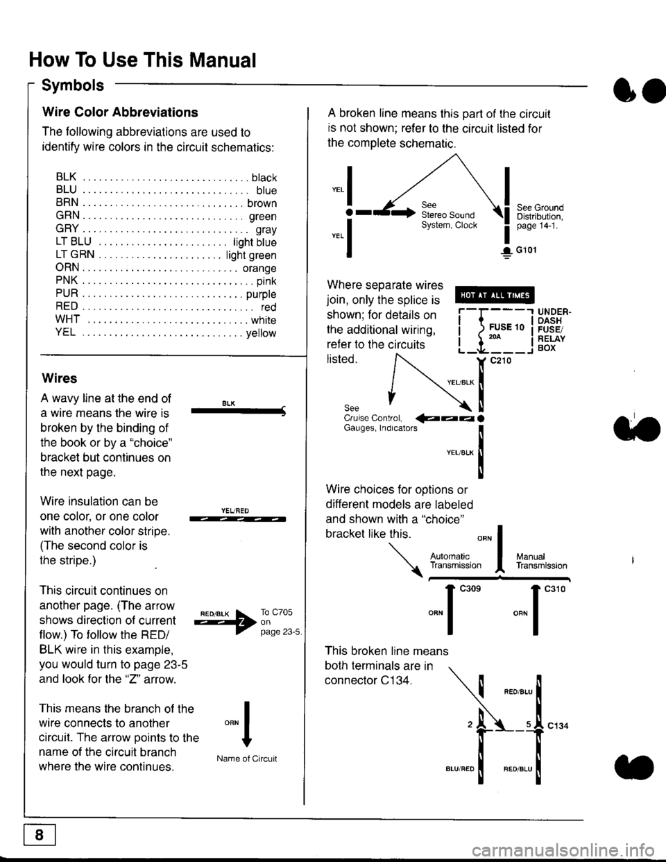
Wire Color Abbreviations
The following abbreviations are used to
identify wire colors in the circuit schematics:
BLK.... .........b|ack
BLU.... ......... blue
BRN.... ,....... brown
GRN.... ........ green
GRY.... ......,.. gray
LTBLU . .....lightbtue
LTGRN. ....lightgreen
ORN.... ....... orange
PNK .... .......,.. pink
PUR .... ........ purple
RED .... .......... red
WHT... .........white
YEL .... ........ yellow
A broken line means this part of the circuit
is not shown; refer to the circuit listed for
the complete schematic.
"ral
o
-.1
See GroundDistribution,page 141.
I G101
Where separate wires
join, only the splice is
shown; for details on
the additional wiring,
refer to the circuits
listed.ili::i
{[
UNDER-OASHFUSE/RELAYBOX
Wires
A wavy line at the end of
a wire means lhe wire is
broken by the binding of
the book or by a "choice"
bracket but continues on
the next page.
Wire insulation can be
one color, or one color
with another color stripe.
(The second color is
the stripe.)
This circuit continues on
another page. (The arrow
shows direction o{ current
flow.) To tollow the RED/
BLK wire in this example,
you would turn to page 23-5
and look for the "2" anow.
This means the branch of the
wire connects to another
circuit. The arrow Doints to the
name of the circuit branch
where the wire continues.
8LK-Cruise Control, €�aaaGauges, Indrcalors
!YEUsLK
Ttl
Wire choices for options or
different models are labeled
and shown with a "choice"
bracket like this.
This broken line means
both terminals are in
connector C134.
a.
+##l:i""lManuallransmission
ryil;::,
.""1
""'
"""1".'0
I
""^l
:-lName of Circuit
Page 1840 of 2189

Ground-to-Components I ndex
f.,lONOTE: All ground wires are BLK unless otherwise noted.
GroundPageComponents or Circuit Grounded
Battery (BLKYEL)
Steering pump bracket
t+-rg ITransmission housing
l
G101
(-1)
G101
(-2)
14-2
and
14-3
ano
14-1
Powertrain or engine control module (PG1 and pG2 are BLK: LG1 and LG2 are
BRN/BLK), EGR control solenoid valve (CW, EGR valve and lift sensor (Dt6yS enginewith M,/T), Engine coolant temperature switch, pGM-Fl main relay, power steeringpressure switch (USA), Primary HO2S (D16Y5 engine with l\/,/T), Vehicle speed sensor,VTEC pressure switch (D16Y5/D16Y8 engines), CKF sensor (BRN/BLK), Transmission
control module (CYf) (Pc1 is BLK: LG1 is BRN/BLK)
Shielding betvveen the PCM or ECM and these components (all have BRN/BLK wires):
CKF sensor, TDC/CKP/CYP sensor. Primary and secondary heated oxygen sensors.
Knock sensor (CWDl6YB engine), Mainshaft speed sensor (AiT except CVT),
I Countershaft speed sensor (A/T except CVf)
Shielding between the TCM and these components (CVT) (all have BRN/BLK wires):
Drive pulley speed sensor, Driven pulley speed sensor, Secondary gear shaft
speed sensor
Powertrain or engine control module (PG1 and pG2 are BLK; LG1 and LGz are
BRN/BLK), EGR control solenoid valve (D16Y5 engine), EGR valve (Dt685), Engine
coolant temperature switch, Fuel pressure regulator shut-off solenoid valve (D1685),
PGM-FI main relay, Power steering pressure switch (USA), Vehicle speed sensor, VTECpressure switch (All except D16Y7 engine), CKF sensor (A
except 81642) (BRN/BLK)
Shielding between the PCM or ECM and these components (all have BRN/BLK wires):
CKF sensor, TDC/CKP/CYP sensor, Primary and secondary heated oxygen sensors,
Knock sensor (All except D16Y7 engine), i/ainshaft speed sensor (Arf except CW),
Countershaft speed sensor (A,/T except CVf), Drive pulley speed sensor (CW), Drivenpulley speed sensor (CVT), Secondary gear shaft speed sensor (CVf)
I Badiator fan motor, Right front parking/turn signat tight, Right headtight
G20214-4I Cruise control actuator, Left front parking/turn signal lights, Left headlight, Rear window
I washer motor, Windshield washer motor, Washer fluid level switch (,99-'00 Canada)
G401| +-o
and
14-7
Accessory power socket, Brake fluid level switch, Clutch interlock switch (M/T), Clutchswitch (lillT with cruise/D16Y5 engine with MfD, Combination wiper switch (Z wires),
Cruise control main switch, Cruise control unit, Dash lights brightness controller, Data
link connector, Daytime running lights control unit (Canada), Gauge assembly, Horn('96-'97 models), Integrated control unit, Interlock control unit (ArI), Keyless door lock
control unit ('99-'00 models with keyless), Moonroof close and open relays, Moonroof
switch, Park pin switch (A/r), Power window relay, Rear window defogger relay, Rear
window defogger switch ('96-'98 models), Steering lock, Stereo radio tuner (,96-,98
USA: LX, EX, and HX), Turn signal/hazard relay, Windshield wiper motor.....plus
everything grounded through G402
6-6
Page 1870 of 2189
- Gl, G2, G3, and G403
BATTERY
tl
tl
ABSPUMPMOTORSTEERINGPUMPBRACKET
I
I
TRANS-MtsstoN
I
I
PagePHOTO
I
44-5
I
IJ
I
I
T3PHOTO 20
I
I
r4Ptlofo 13
IL
BFI{
1
PHO|O 20G3PHOTO 13
c360
!. c403G1
- G751, G771, and G801
CONDENSERFANi,OTORPage
,l
I
I
I
SRS UNITPage 47PHO|OT0vtEw 51
I
tlL------J
17
c753
G751
GFY (20)OTGFNGFY (r9)or GFN
!. G801
14-13
Page 1954 of 2189
A/C Compressor Controls
- AllModels
cc5)M7
BLU/RED
?
\a
@
&cCOMPRESSORCLUTCHRELAYPHOfO 10
a
! ,acc, : POWERTRATN! arn.^-^,o..^, I or ENGINE
! ii i"i-iiii"v i.,ii.r | fi 3$18.
I A/C request ! (pCM or ECM)I (ACSJ a pHOrO a6L------J vtEw 70
REO
BEO
1
RED
BLU/FEO
2
BLU/FEO
ct31
:"1'!i'------;
Fi:rz, a ='e6-'s8: A|| moders except D1685vtEw 21 '99100: D16Y5 with l\illT'* = 96-'98: All models
ir'iio ," 99. 00: Dt6y5 wth t\4/t Dl6Bb
atcPRESSUREswtTcH
c752
c1
".,n""t 1(
".r-".rf, "tA% "
"."-:,fi tfr,]4.
v
To facing page ('96''98 models)or page 62'2 ( 99-'00 models).
-Yl
-t---------Jc353
c2'14
vtEW21
c209
A,/CCOMPRESSORCLUTCH
COMPRESSORTHERMALPROTECTOR
UNDER-HOODFUSE/RELAYBOXf-T-*-'.T'---l H53.',EPA?' i-l-------
i iflH* !F,?r",, i f6F"'.i:.",",
| tsBi":J;"#il ! a T| | oaoe 1o-9. ! I I See PowerL_J1_j:_-_j ! H Distriburion.e Y c42o i I
pase 1o-1.
***
f ifi"l'
^ see power ! |
62
!(on bracket)
Page 2141 of 2189

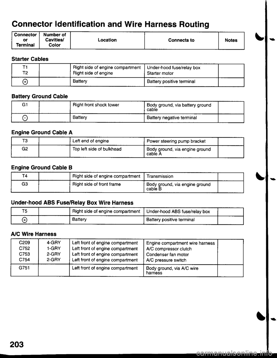
Connector ldentification and Wire Harness Routing
Connector
or
Terminal
Number of
Cavities/
Color
LocationConnects toNotes
Starter Cables
T1
r2
Right side of engine compartment
Right side of engine
Under-hood luse/relay box
Staner motor
t+lBatteryBattery positive terminal
Battery Ground Cable
Right front shock towerBody ground, via battery ground
cable
oBatteryBattery negative terminal
Engine Ground Cable A
t!tLeft end of enginePower steering pump bracket
Too left side ot bulkheadBody ground, via engine ground
cable A
Engine Ground Cable B
T4Bight side of engine compartmentTransmission
(ritRight side of front frameBody ground, via engine ground
Under-hood ABS Fuse/Relay Box Wire Harness
tcRight side of engine compartmentUnder-hood ABS fuse/relay box
oBatteryBattery positive terminal
A,/C Wire Harness
c209
wtJl/,\-7Ee
c754
4-GRY
1.GRY
2-GRY
2-GRY
Lefl front of engine compartment
Left front of engine compartment
Lefl front of engine compartment
Left tront of engine compartment
Engine compartment wire harness
A,/C compressor clutch
Condenser fan motor
A,/C pressure switch
G751Left front of engine compartmentBody ground, via A,/C wireharness
Page 2181 of 2189

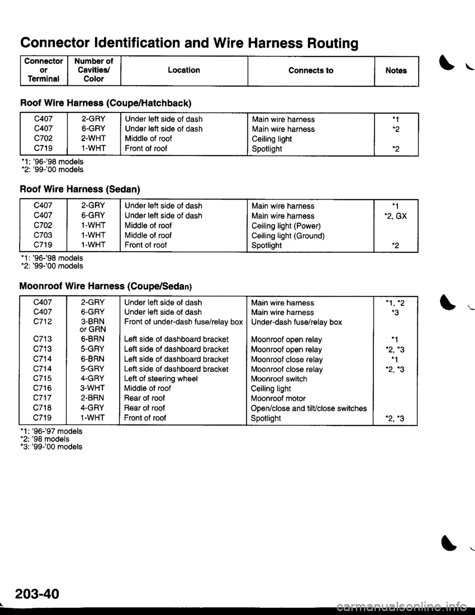
Connector ldentification and Wire Harness Routing
Connector
or
Terminal
Number of
Cavities/
Color
LocationConnects toNotes
Roof Wire Harness (Coupe/Hatchback)
c407
c407
c702
c719
2-GRY
6-GRY
2-WHT
1-WHT
Under lett side of dash
Under left side of dash
Middle of roof
Front of roof
Main wire harness
Main wire harness
Ceiling light
Spotlight
.2
'l : '96-'98 models'2: '99-'00 models
Rool Wire Harness (Sedan)
.1 : '96-'98 models.2: '99100 models
Moonroof Wire Harness (Coupe/Sedanl
*1: '96'97 models'2: '98 models"3: '99r00 models
c407
c407
c702
c703
c719
2-GRY
6-GRY
1-WHT
1-WHT
1-WHT
Under left side of dash
Under left side of dash
Middle of roof
Middle of roof
Front of roof
Main wire harn€ss
Main wire hamess
Ceiling light (Power)
Ceiling light (Ground)
Spotlight
"1
-2, GX
.2
c407
c407
c712
c713
c713
c715
u/ to
c717
c718
c719
2.GRY
6-GRY
3-BRN
or GRN
6-BRN
5-GRY
6.8RN
5-GRY
4-GRY
3-WHT
2-BRN
4-GRY
1-WHT
Under left side of dash
Under left side of dash
Front of under-dash fuse/relay box
Left side of dashboard bracket
Left side of dashboard bracket
Left side of dashboard bracket
Lett side of dashboard bracket
Left of steering wheel
Middle of roof
Rear of roof
R€ar of root
Front of roof
Main wire harness
Main wire harness
Undsr-dash fuse/relay box
Moonroof open relay
Moonroot open relay
Moonrool closa relay
Moonroof close relay
Moonroot switch
Ceiling light
Moonroof motor
Open/close and tiluclose switches
Spotlight
.3
'1
'2,.3
-1
'2,'3
'2,.3
203-40