1999 HONDA CIVIC c131 connector
[x] Cancel search: c131 connectorPage 422 of 2189
Secondary Heated Oxygen Sensor {secondary HO2S) (Sensor 2l
*'t : D16Y8 engine*2:'99 - O0 m;dels except D16Y5 engine with M//T
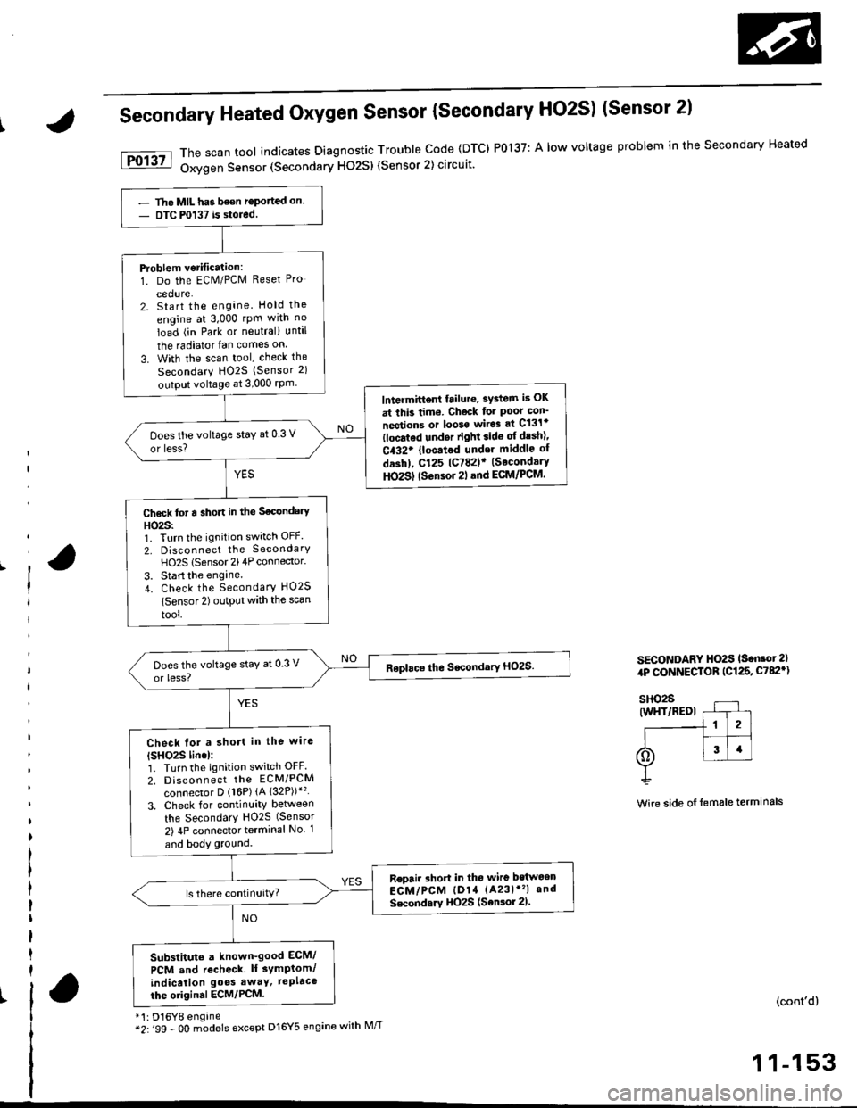
The scan tool indicates Diagnostic Trouble Code (DTC) P0137: A low voltage problem in the Secondary Heated
Oxygen Sensor (Secondary HO2S) (Sensor 2) circuit'
SECONDARY HO2S ls.n.ot 2),rP CONNECTOR (C125, C782')
Wire side oI temale terminals
(cont'd)
1 1-153
- Tho MIL has been reported on- DTC P0137 is stored.
Problem verification:1. Do the ECM/PCM Reset Pro
cedure.2. Start the engine. Hold the
engine at 3,000 rpm wlth no
load (in Park or neutral) until
the radiator fan comes on
3. With the scan tool, check the
Secondary HO2S (Sensor 2)
output voltage at 3,000 rPm
lntermittent frilure, sYdem is OK
at this tim6. Check for Poor con'
nections or loolo wir.3 at C131t(locatod undor right.ido of desh)'
C432. {located under middle of
dashl, cl25 lc782lr {SecondaryHO2S) tsensor 2l .nd ECM/PCM.
Does the voltage staY at 0.3 V
or less?
Ch6ck tot a sho.t in the S€condery
HO23:'1. Turn the ignition switch OFF.
2, Disconnect the SecondarY
HO2S lSensor 2)4P connector.
3. Start the engine.
4. Check the SecondarY HO2S
lsensor 2) output with the scan
tool,
Check tor a short in the wire
{SHO2S linel:1. Turn the ignition switch OFF.
2. Discon n ect tho EcM/PCM
connector D {16P) {A (32P))*'�
3. Check for continuity between
the SecondarY H02S (Sensor
2) 4P connector terminal No 1
and body ground.
R€pair short in tho wire bstwoen
ECM/PCM lD14 (A231*'�| and
Secondarv HOzS (Sensor 2).
Substitute a known-good ECM/
PCM and recheck lf 3ymptom/
indicalion go€s awaY, tePltco
the oiigin.l ECM/PCM.
Page 426 of 2189
tFo135l
iPol4tl
Heated Oxygen Sensor (HO2SI Heater
('96 - 98 Mbdels,'99 - 00 Dl6Y5 engine with M/Tl
*: p0141 (To page 11-158)**: D'16Y8 engane
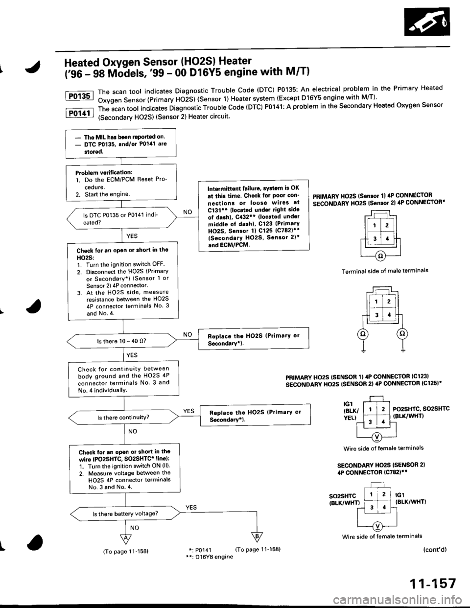
The scan tool indicates Diagnostrc Trouble code (DTC) P0135: An electrical probl€m in the Primary Heated
Oxygen Sensor (Primary HOiS) (Sensor 1) Heater system (Except D16Y5 engine with M/T)'
The;can tool indicates Diagnostic Trouble code (DTC) P0141: A problem in the secondary Heated oxygen sensor
(secondarv HO2S) (Sensor 2) Heater circuit.
PRIMARY HO2S (Son.or 1l aP CONNECTOR
SECoNDARY HO2S tsensor 2l ilP CONNECTORT
Terminal side of male terminals
PRIMARY HOzS (SENSOR 1) 4P CONNECTOR ICl23I
SECONDARY HO2S ISENSOR 2) 4P CONNECTOR {C125I*
PO2SHIC, SO2SHTCIBLK/WHT)
Wire side of female terminals
SECONDARY HO2S ISENSOR 2),tP CONNECTOR 1C782)'*
so2sHTC{BLK/WHT)
Wire side oI female terminals
I(cont'd)
11-157
- The MIL h.s boen Jeponed on.- DTC P0135, and/or Polal .re
stoled.
Problem verificationl
1. Do the ECM/PCM Reset Pro-
ceduae,2. Start the enginelniermittent tailura, sYttam i! OK
at thi3 time, Chsck for Poor con'
neciion3 or loose wilG3 at
C131** (locat.d undo. right sido
ot dashl, C{32** (loc.ted under
middle ol dashl, C123 (PrimarY
HO2S. Sansor 1) C125 lc782l*r
{Socondery H02S, Sonsor 2l'
and EcM/PcM.Check for an open or 3hort in tho
HO25:1. Turn the ignition switch OFF.
2. Disconnect the HO2S (Primary
or Secondary*) (Sensor 1 or
Sensor 2) 4P connector'3. At the Ho2s side, measure
resistance between the HO2S
4P connector terminals No. 3
and No.4.
ls there 10 - 40 0?
Check for continuity between
body ground and the HO2S 4P
connector terminals No. 3 and
No.4 individually
Chock for an oPen ot short in tho
wire |PO2SHTC, SO2SHTC* linol:
1. Turn the ignition switch ON (ll).
2. Measure voltage between the
HO2S 4P connector terminalsNo.3 and No.4.
(To page 11'158)
Page 428 of 2189
IHeated Oxygen Sensor (HO2S) Heater
i'ss - oo Mb-dels except D16Y5 engine with M/Tl
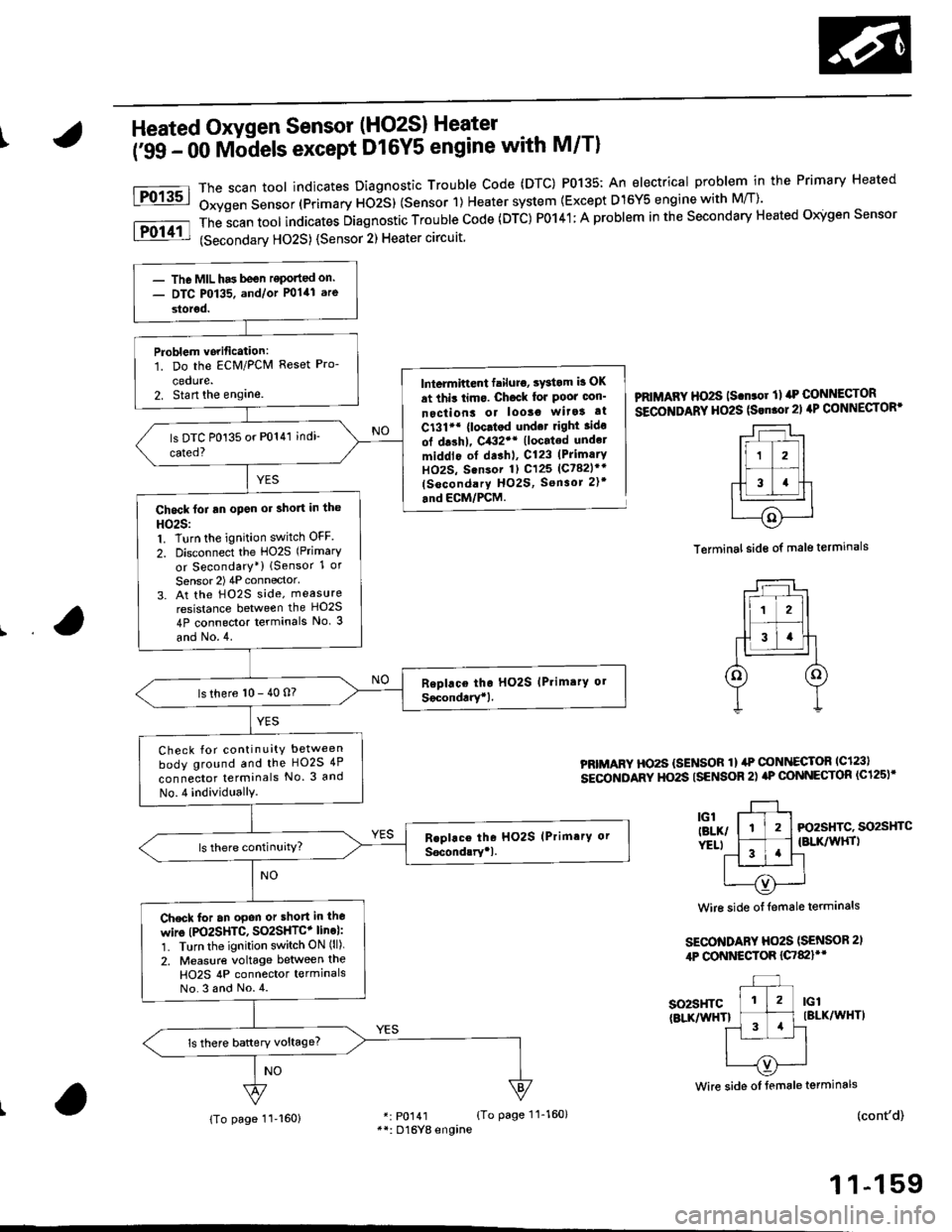
The scan toot indicates Diagnostic Trouble Code (DTC) P0135: An electrical problem in the Primary Heated
Oxygen Sensor (Primary ttOiS) (Sensor 1) Heater system {Except D15Y5 engine with M/T)'
The
-scan tool indicates Diagnostic Trouble Code (DTC) P0141; A problem in the Secondary Heated Oigen Sensor
(Secondarv HO2S) {Sensor 2) Heater circuit
Fo13sl
Fol11l
lntermiftent failuro, sYstom b OK
at thit limo. Ch6ck lor Poor oon'
nectiont or looso wita! at
C131'* {loc.tod und.t right ido
ol drshl, C432'* (located undel
middlo of dashl, C123 (PrimarY
HOzS, Sensor 1) C125 (Ct82lr'
(socondary HO2S, Sensor 2)t
.nd ECM/PCM.
PRIMAFY HO2S ls.n.or ll rrP CONNECTOR
SECOITIDARY HO2S (Srn.ol21 4P CONNECTOR'
Terminal side of male terminals
PRIMARY HO2S {SENSOR 1} ilP @NI{ECTOR lc123l
sEcoNDARY HO2S ISENSOR 2) aP @NNECTOR (C125)'
3l-, l-tl-t Fo2sHrc. so2sHrc
ver.t l ^-1 .'l {BLK/wHrl
11 '!'l-l
| --=- Iu----{v)'---..-'
Wire side of {emale terminals
SECO'TIDARY Ho2S (SENSOR 2,
4P CONNESTOR {C7&llt'
so2sHTc(BLKnflHTlIBLK/WHT)
(cont'd)
1 1-159
Wire side oI female terminals
r: p0141 {To page 11-160}**: D16Yg engine
- The MIL has been reponed on.- DTC P0135. and/or P0141 are
storod.
Problem vorification:1. Do the ECM/PCM Reset Pro-
cedute.2. Stan the englne.
Chock foi an open or short in the
HO25:1. Turn the ignition switch OFF
2. Disconnect the HO2S (Primary
or Secondary*) lSensor 1 or
Sensor 2) 4P connector'
3. At the H02S side, measure
resistance between the HO2S
4P connector terminals No. 3
and No.4.
ls there 10 - 40 n?
Check for continuity between
body ground and the HO2S 4P
connector terminals No. 3 and
No.4 individuallY.
Check for an opon or short in lho
wire (PO2SHTC, SO2SHTC+ line):'1. Turn the ignition switch ON (ll).
2. Measure voltage between the
H02S 4P connector termlnalsNo.3 and No.4.
{To page 11-160}
Page 448 of 2189
Electrical Load Detector (ELDI {'96 - 98 Models,'tn - 00 D16Y5 engine with M/T}
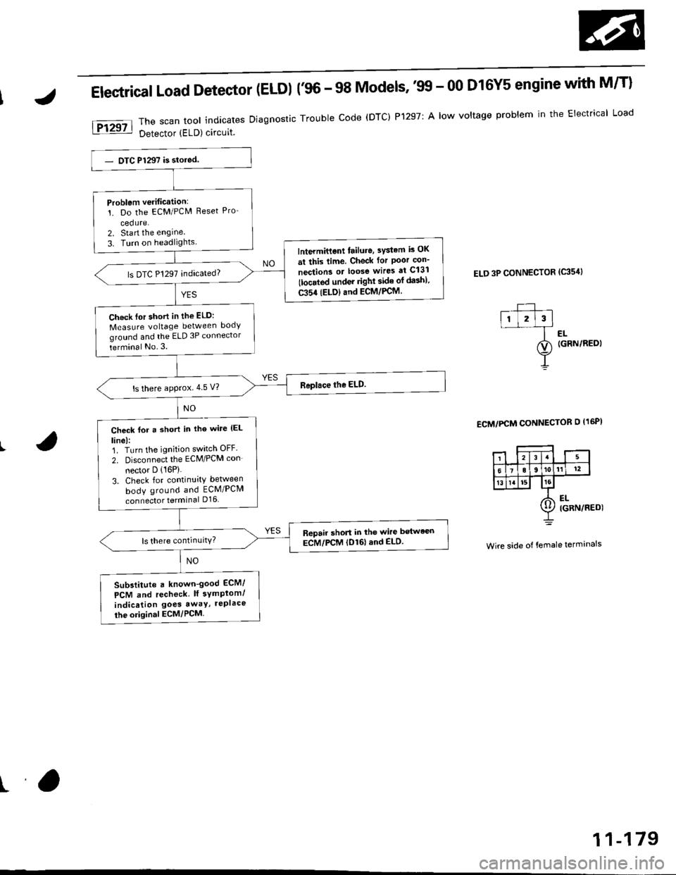
The scan tool indicates Diagnostic Trouble code (DTC) P1297: A low voltage problem in the Electrical Load
Detector (ELD) circuit.
ELD 3P CONNECTOR (c35'rl
l-- ,ll l2l3l--f ..
ao (GRN/REDI
Y
ECM/PCM CONNECTOR O I16PI
Wire side of female terminals
Problem verification:'!. Do the ECM/PCM Reset Pro-
cedure.2. Sta rt the engine
3. Turn on headlightslntermittent tailure, sYstem is OK
at this time. Check for Poor con-
nection3 or loose wires at C131
tlocated under righl side of da3h).
C354 (ELDIand ECM/PCM.
ls DTC P1297 indicated?
Ch.ck lor short in the ELD:
Measure voltage between body
ground and the ELD 3P connector
terminal No.3.
ls there approx.4 5 V?
Check for a short in tho wile (EL
linel:1. Turn the ignition switch OFF'
2. Disconnect the ECM/PCM con
nector D (16P)
3. Check for continuity between
body ground and ECM/PCM
connector terminal D16
R6pair short in the wire between
ECM/PCM (D161and ELD.
Substitute a known-good ECM/
PCM and recheck lf symplom/
indication goes awaY, rePlace
the original ECM/PCM
ra
11-179
Page 449 of 2189
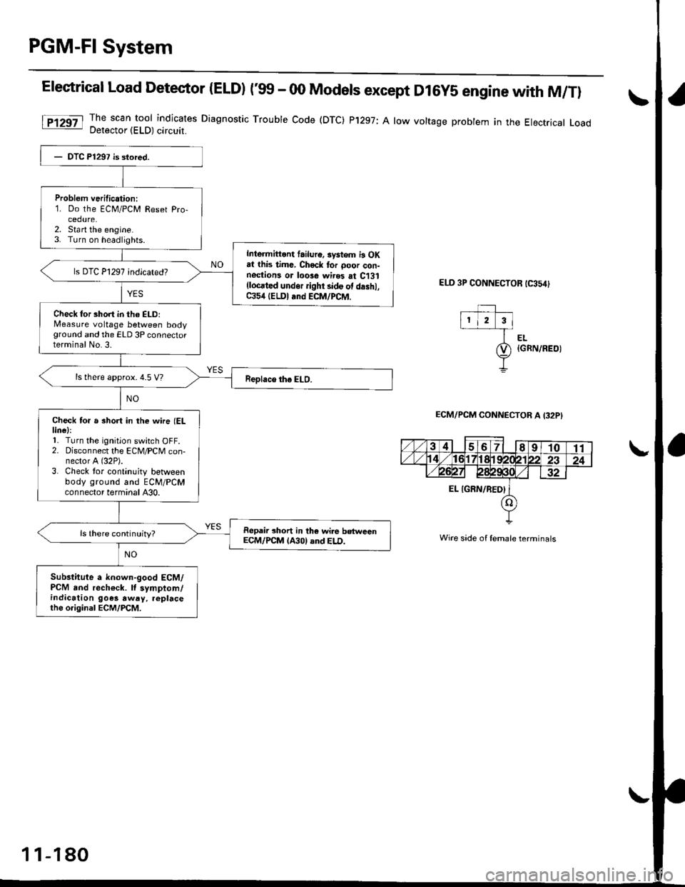
PGM-Fl System
Elestrical Load Detector |ELD) t'glf - 00 Models except D16y5 engine with M/Tl
The scan tool indicates Diagnostic Trouble Code (DTC) P'1297; A low voltage probtem in the Electrical LoadDetector (ELD) circuit.
ELD 3P CONNECTOR tC354)
EL{GRN/REOI
ECM/PCM CONNECTOB A I32PI
Wire side of lemale terminals
Problem verilication:1. Do the ECM/PCM Reset Pro-cedure.2. Sta rt the engine.3. Turn on headlights.
Inlermittont failur6. systom i3 OKat this time, Chock tor ooor con-nestions or loose wires at C131(locrted undor ight side ot d.shl,C354 (ELDI and ECM/PCM.
Check for short in th6 ELD:Measure voltage between bodyground and the ELD 3P connectorterminal No.3.
ls there approx. 4.5 V?
Check to. a short in the wne (ELlinel:'L Turn the ignition switch OFF.2. Disconnect the ECM/PCM con-nector A (32P).
3. Check tor continuity betlveenbody ground and ECM/PCMconnector terminal A30.
Repair short in the wile betweenECM/PCM lA30) and ELD.ls there continuity?
Sub3titute a known-good ECM/PCM and rech€ck. It symptom/indication goes away. replacethe o.iginal ECM/PCM.
1 1-180
Page 450 of 2189
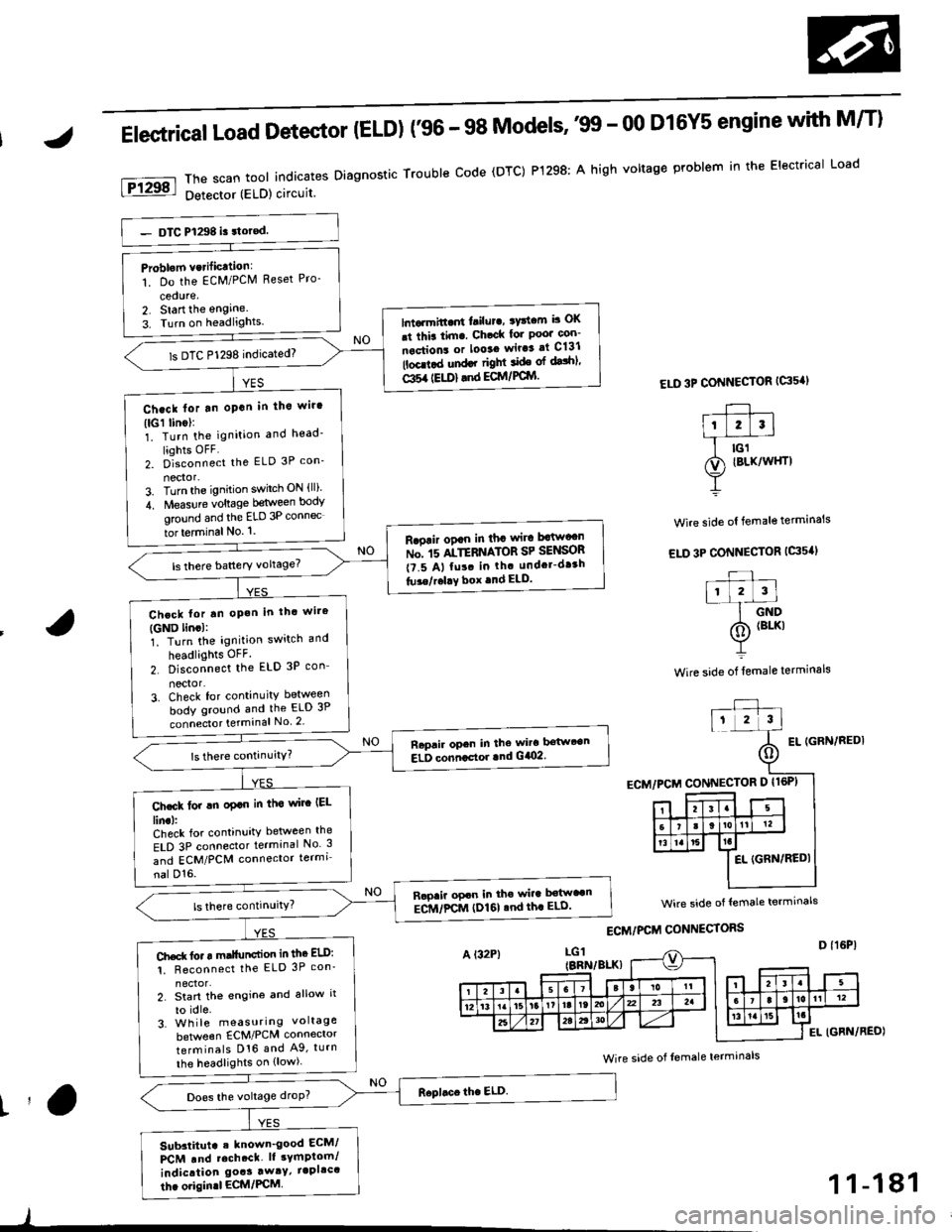
Elestrical Load Detector (ELD) f96 - 98 Models''99 - 00 D16Y5 engine with M/T)
ThescantoolindicatesDiagnosticTroubleCode(DTC)P1298:AhighvoltageproblemintheElectricalLoad
Detector (ELD) circuit
ELD 3P CONNECTOR {G's'I
Wire side ol female terminals
EL IGFN/REDI
Problom vcrificttion:
1. Do the EcM/PClVl Reset Pro-
cedure,2. Start the engine.
3. Turn on headlights.lntarmitt..rt l.ilur., ryttcm b OK
.t thia tim. Ch.ck lor Poo' con-
nections or looaa wir.3 at C131
lbcd.d und.r right ide ol dalhl'
Gl5a {EU)} .nd ECM/PCIYI
ls DTC P1298 indicated)
Ch.ck lor tn oPan in tho wir'
(lGl linol:1. Turn the ignition and head'
liohts OFF2. D]""onn""t the ELD 3P con_
nector-3. Turn the ignition switch ON {ll)'
4. Measure voltage between body
ground and the ELD 3P connec
tor terminal No. '1.
R.oair ogan in tha wira Mw"n
ru". rs ltTEnrlton SP SelSOn
t?.5 A, fu!. in th. undcr-dr3h
tu3e/r.l!Y box .nd ELD.
Chcck lor tn oP.h in thc wire
{GND lincl:1. Turn the ignition switch and
headlights OFF.
2. Disconnect the ELD 3P con_
nector'3. Check for continuity between
body ground and the ELD 3P
connecto. terminal No 2
Raprir opcn in the wira bstwt€n
ELD conncctor lnd G/O2.
Ch.ck lor !n oplo in tha wirc IEL
lin.l:Check for continuity between the
ELD 3P connector terminal No 3
and ECM/PCM connector termi
nal D'16.
Rapaii opcn in the wira b€tw"n
ECM/FCM (I)161 .nd th. ELD'
Ch.d( fo. r m.llunction in thc ELD:
1. Reconnect the ELD 3P con'
2. Start th€ engine and allow it
to idle.3. Wh ile measuring voltage
beNveen ECM/PCM connector
terminals D16 and A9, turn
the headlights on {low).
Does the voltage droP?
Sub3titut. . known_good ECM/
PCM .nd rcch.ct. lt sYmptom/
indication goas away/ iapllc'
thc origin.l ECM/PCM
wire side of lemale termrnals
Wire side of Iemale terminals
t'a
)
1 1-181
Page 458 of 2189

[F16551l Th" ""un toot indicates Diagnostic Trouble Code (DTC) P1681: TIVA,/TMB signal line failure
Problem verification:1. Do the ECM Reset Procedure.
2. Drive the vehicle Ior several
miles at varying speeds
lnt.rmittent failure, system is OK
at ihis time. Check tor Poor con-
nections or loos€ wires at C131
llocated under right side of dash),
C438 ITCM) and ECM.
ls DTC P1655 indicated?
Check lor an oPen in the wire(TMA line):1. Turn the ignition switch OFF
2. Disconnect ECM connector C(31P)from the ECM
3. Turn the ignition switch ON (ll).
4- Measure vo ltag e between
ECM connector terminal Cg
and body ground.
Check for a short in the wire
ITMA line,:Measure voltage between TCM
22P connector terminal No 7 and
body ground.ls there battery vohage?
Ropair shod in the wire bstwe€n
the EcM (C!l) and the TcM.ls there battery voltage?
Check for an open in the wire
{TMB line}:1. Turn the ignition switch OFF
2. Reconnect ECM connector c(31P).
3. Disconnect the 22P connector
from TCM.4. Turn the ignition switch ON (ll).
5. Measure vo ltage between
TCM 22P connector termlnal
No. 6 and body ground.
Repair open in the wire between
th€ EcM {Ca) and the TcM.
Check for a 3ho.t in the wire
{TMB lin6,:Measure voltage between ECM
connector terminal C30 and bodyground,
ls there battery voltage?
Substitute a known'good ECM
and recheck. It symPtom/indica'tion goes away, teplace the origi-
nal ECM.
Reoair short in the wile b6tween
the ECM {C30} and the TCM.ls there baftery voltage?
f,epair open in the wire between
the EcM (C30) and the TcM.
IJA/T Signal (TMA/TMBI ('96 - 98 Dl6Y5 engine with GW)
ECM CONNECTOR C 131P}TMA IGRYI
fcu22PCONNECTOR
ll
TMB*{PNK}
231678910
1t'12131415161718
232a252930
Wire side oI temale
terminals
tl,
1 1-189
Page 544 of 2189

\J
Fuel Tank Pro3sure sensor 196 D16Y8 engine (coupe).'97 D15Y7 engine {coupe: KL model, sedan: KL (LX) modeu,'97
D16Y8 engine (coupe: all models, sedan: KL model, '98-all models) '99 - 00 D16Y5 engine with M/Tl:
\
PTANK
{LT GRNI
vcc2(YEL/BLU}
Wire side oI female terminals
FUEL TANKPRESSURE SENSOR3P CONNECTOR (C7921
sG2IGRN/8LK)
Foc2l::il":"toolindicatesDiagnosticTroublecode(DTc)P0452:A|owvo|tageprob|emintheFue|TankPressure
The fuel tank pressure sensor converts fuel tank absolute pressure into electrical signals and inputs the EcM/PCM.
OUTPUTVOLTAGEtvt4.5
-? kPa(-50 mmHg,-2 in.Hg)
ECM/PCM CONNECTOR O I16P)
Wire side of female terminals
+7 kPs150 mmHg,2 in.Hg)
PRESSURE
(cont'd)
11-275
- The MIL has been reported on- DTC P0452 is stored.
Check the vacuum lines:
Check the vacuum lines of the
fuel tank pressure sensor for mis-
routing, leakage, breakage and
cloggrng.
Are the vacuum lines OK?
Problem v€ritication:1. Do the ECM/PCM Reset Proce
dure.2. Remove the luel fill caP.
3. Turn the ignition switch ON lll)4. Monitor the FTP Sensor volt_
age with the Honda PGM
Tester, or measure voltage
between bodY ground and
ECM/PCM terminal Dl5.lntermittent tailuro, sYstem i5 OK
dt this timo. Chock for Poot con-
neciion3 or loose wir* at C131
llocatod under right side ot dashl,
C4O1 (located .bove under'da3htuso/ielay box), C574 1C568)*
{located under acc€ss Panell.C792 lfuel tank pressule sen3or)
and EcM/PCM.
ls there approx. 2.5 V?
Check tol an op€n in wite (VCC2
line):1. Turn the ignition switch OFF
2. Reinstallthe fuel fill caP.3. Disconnect the fuel tank Pres'sure sensor 3P connector-4. Turn the ignition switch ON (ll)
5, Measure voltage between the
fuel tank pressure sensor 3P
connector No. l terminal and
No. 2 terminal.
Repair open in the wite betweenthe fuel tank Pr€s3ure a€n3or andth6 EcM/PcM (D1ol.ls there approx. 5 V?
(To page 11'276)