Page 1054 of 2189

Disassembly
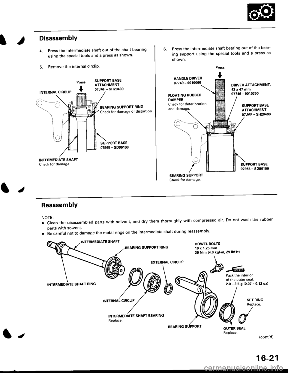
Press the intermediate shaft out of the shaft bearing
using the special tools and a press as shown.
Remove the internal circliP
Press
I
SUPPORT BASEATTACHMENT07JAF - SH20400INTERNAL CIBCLIP
BEARING SUPPORT RING
Check for damage or distortion
6. Press the intermediate shaft bearing out ot the bear-
ing support using the special tools and a press as
shown.
HANOLE DRIVER
0?749 - 00'�10000
Press
I
DRIVER ATTACHMENT,12x47 mm07746 - 0010300FLOATING RUBBEB
DAMPERCheck for deterioration
and oamage.SUPPORT BASE
ATTACHMENT07JAF _ SH20it00
BEARING SUPPORT
Check for damage
I sErR'NG
A4 Reolace
VUOUTER SEALReplace.(cont'd)
ReassemblY
NOTE:
. clean the disassembted parts with solvent, and dry them thoroughly with compressed air' Do not wash the rubber
parts with solvent.
. Becareful not to da mage the metal ringson the intermediate shaftduring reassembly'
BEARING SUPPORT RINGDOWEL BOLTS10 x 1.25 mm39 N.m 14.0 kgf.m,29 lbIftl
EXTERNAL CIRCLIP
Pack the interiorof the outer seal.2.0-35s10.07-012oz)
INTERNAL CIRCLIP
INTERMEDTATE SHAFT BEARING
Replace,
INTERMEDIATE SHAFT RING
lJ
16-21
Page 1055 of 2189
lntermediate Shaft
Reassembly (cont'd)
1. Press the intermediate shaft bearing into the bear-ing support using the special tools and a press asshown.
Prass
I
DRIVER ATTACHMENT,52x55mm07746 - 001 0(X)
Seat the internal circlip in the groove of the bearingsuppon.
Press the intermediate shaft into the shaft bearingusing the special tools and a press.
Praa.r
I
@---
LJ
INTERMEDIATE SHAFT
DRIVER ATTACHMENT,35 mm LD.
16-22
Seat the external circlip in the groove of the inter-mediate shaft.
Install the outer seal into the bearing support usingthe special tools as shown.
NOTE: Install the seal ftush with the bearing sup-port.
Pre$
t HANDr.r DRTVER- 0011r(x)0
Pack the Interiorof the ouler seal.2.0- 3.5 g {0.07 -0.12 ozl
OUTEN SEAL
Install the new set ringgroove.
ORIVER ATTACHMENT,52x55mm077i16 - 0010/O0
in the intermediate shaft
Page 1124 of 2189

Ball joint Boot Replacement
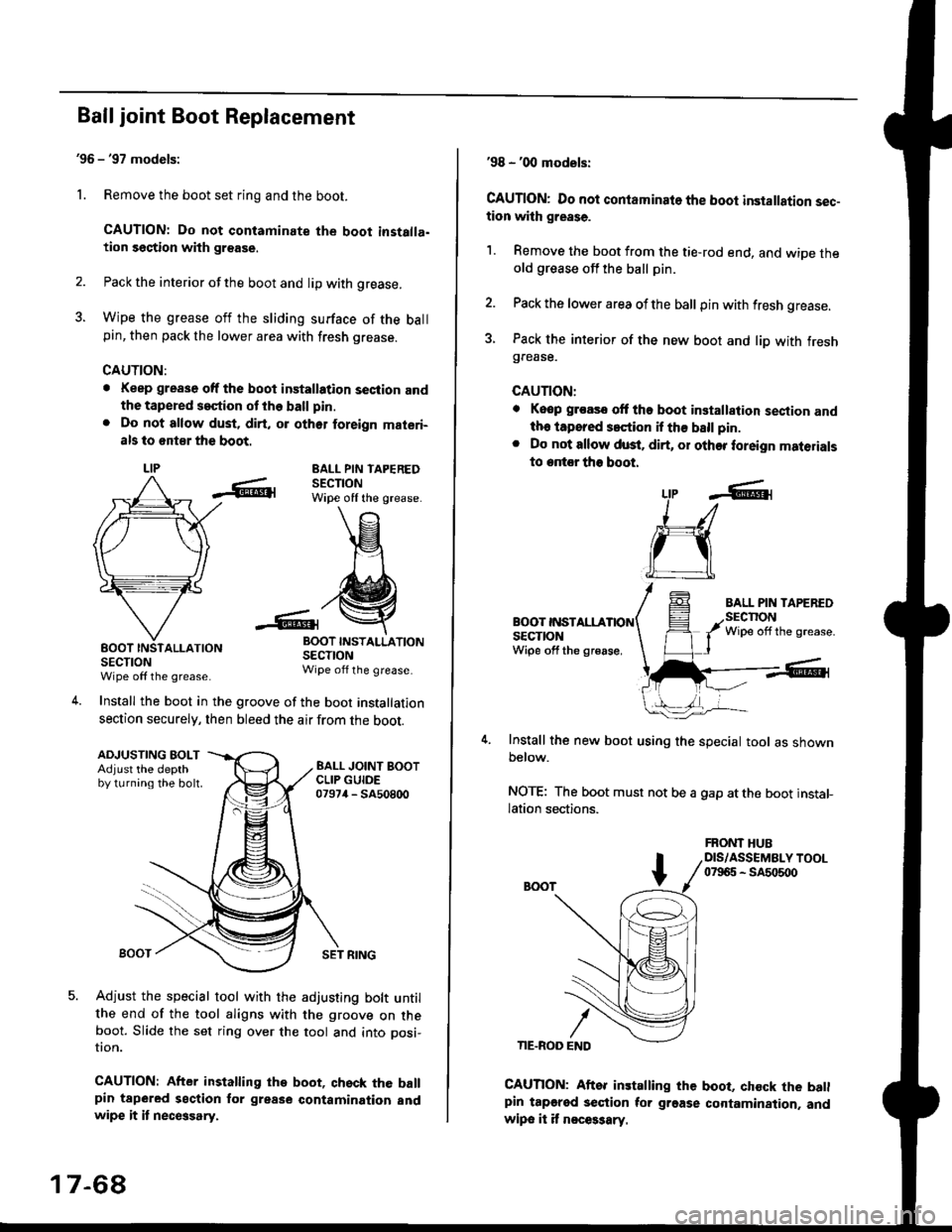
'96 - '97 models:
1. Remove the boot set ring and the boot.
CAUTION: Do not contaminate the boot installa.tion section with grsase.
2. Pack the interior of the boot and lip with grease.
3. Wipe the grease off the sliding surface of the ballpin, then pack the lower area with fresh grease.
CAUTION:
. Keep grease off the boot installation seciion andthe tapered s€ction ot the ball pin.
. Do not allow dust, dirt, or oth6r foreign materi-
als to 6nt8r the boot.
LIPEALL PIN TAPEREDSECTIONWipe off the grease.
INSTALLATION
SECTIONWipe off the grease.
Install the boot in the groove of the boot installation
section securely, then bleed the air from the boot.
-6lrBOOTSECTIONWipe off the grease
4.
ADJUSTING BOLTAdjust the depthby turning the bolt.
SET RING
Adjust the special tool with the adjusting bolt untilthe end of the tool aligns with the groove on theboot. Slide the set ring over the tool and into posi-
UOn.
CAUTION: After installing the boot, qhsck the ballpin tapered section for grease contamination andwipe it it necGsary.
17-68
'98 - '00 models:
CAUTION: Do not contaminato the boot installation sec-tion with grease.
1. Remove the boot from the tie-rod end, and wiDe theold grease off the ball pin.
2. Pack the lower area ofthe ball pin with fresh grease.
3. Pack the interior of the new boot and liD with freshgrease.
CAUTION:
. Keop groasc ott tho boot installalion sestion andth. iapored s.ction if th€ ball pin.
. Do not allow dust. dirt, or other foreign materials
to entor tho boot.
BOOT INSTALLASECTIONWipe off the gr€ase,
Install the new boot using the special tool as shownbelow.
NOTE: The boot must not be a gap atthe boot installation sections.
LtP .6r
J_/
ru
CAUTION: Aftor installing the boot, chock the batlpin tapgred section tor grgase cortamination. andwipe it it n€ces3ary.
FRONT HUBDIS/ASSEMBLY TOOL07965 - SA5o500
Page 1141 of 2189

Front Damper
!Ball Joint Boot RePlacement
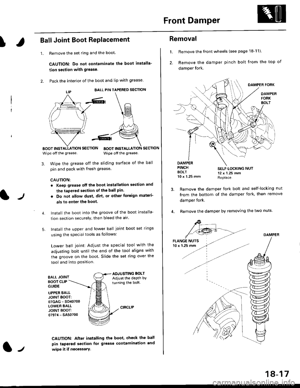
1.Remove the set ring and the boot.
CAUTION: Do not contaminate the boot installa-
tion section with grease.
Pack the interior of the boot and lip with grease
EALL PIN TAPERED SECTION
EOOT INSTALLATION SECTION
Wipe off the grease.BOOT INSTALLATION SECTION
Wipe off the grease.
lJ
3. Wipe the grease off the sliding surface of the ball
pin and pack with fresh grease.
CAUTION:
. Keep grease off the boot installation section and
the tapeled section of the ball pin.
5.
. Do not allow dust, dirt, or other toreign materi-
als to enter the boot.
Install the boot into the groove of the boot installa-
tion section securely, then bleed the atr.
Install the upper and lower ball joint boot set rings
using the special tools as follows:
Lower ball joint: Adiust the special tool with the
adjusting bolt until the end of the tool aligns with
the groove on the boot. Slide the set ring over the
tool and into Position.
BALL JOINTAOJUSTING BOLTAdjust the depth by
turning the bolt.BOOT CLIPGUIDE
4.
UPPER EALLJOINT EOOT:07GAG - SD40700LOWER BALLJOINT BOOT:07974 - SA50700
CAUTION: After installing the boot, check the ball
pin tapsrod section fol grease contamination and
wipe it if necessary.lt
18-17
Removal
l. Remove the front wheels (see page 18-11).
2, Remove the damper pinch bolt trom the top of
damper fork.
DAMPER FORK
OAMPERFORKBOLT
OAMPERPINCHAOLT10 x 1.25 mm
SELF-LOCKING NUT12 x 1.25 mmReplace.
Remove the damper fork bolt and self-locking nut
from the bottom of the damper fork, then remove
damper fork.
Remove the damper by removing the two nuts
DAMPER
Page 1231 of 2189
l}
e\
Body ('96 modell
Doors
Front Door Index (4D) ...20-2
Rear Door Index {4Dl .....20-8
Door fndex lzDl3Dl .......20-14
Emblems
f nstallation 20-118
Exterior
Component Location Index ............... 20-93
*Frame Repair Chart .......... 20-120
* Interior
Component Location Index ............... 20-58
Mirrors
Mirror Rep|acement .................. ......... 20-24
Mirror Holder/Gover Replacement ... 20-25
Rearview Mirror Reolacement .......... 20-25
Moonroof
lndex .......... .....................20-50
Opener Cable/Opener and Latch/
Wiper and Washer
Component Location Index .......... ...,. 20-107
Seats and Seat Belts
Gomponent Location Index .......... ..... 20-73
Sub-frame ....20-119
Windshield, Rear Window and Ouarter Glass
Index .......... .....................20-26
Body {'97 modell
Body ('98 modell
Body ('99 modell
Body ('00 model)
20-123
20-131
20-135
20-141
It
Page 1284 of 2189
Moonroof
Motor, Drain Tube and Frame Replacement
CAUTION:
. Put on gloves to protecl your hands.
. Be careful not to damage the seats, dashboard and other interior trim.
'1. Remove the headliner {see page 20-64).
2. Disconnect the motor connector and glass position switch connector.
NOTE: When removing the motor, detach the connector from the frame, remove the bolts and nuts, then remove the
motor.
3. Remove the glass {see page 20-52).
4. Disconnect the drain tubes, and detach the ceiling light harness.
5. Remove the frame mounting bolts.
NOTE;
. An assistant is helpful when removing the bolts.
. Remove the front bolts last.
6. Detach the rear hooks by moving the frame forward, then remove the frame.
BOLT6x1.0mm9.8 N.m {1.0 kgt m,7.2 tht.hl
6x1.0mm9.8 N m (1.0 kgl.m, 7.2 lbtft)
20-54
\
Page 1288 of 2189

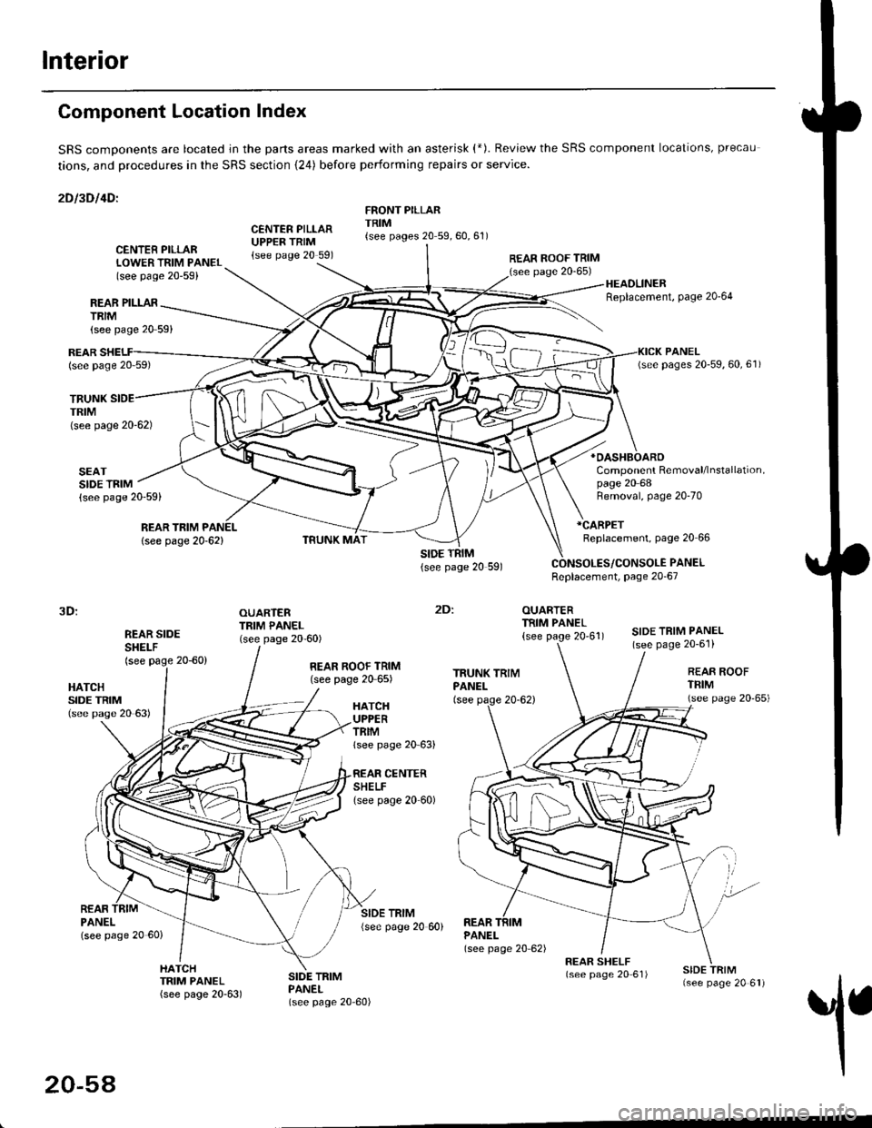
Interior
Component Location Index
SRS comDonents are located jn the parts areas marked with an asterisk (*). Review the SRS component locations, precau
tions, and procedures in the SRS section {24) before performing repairs or service.
2Dl3Dl4Dl
CENTER PILLARUPPER TRIM{see page 20 591
FRONT PILLARTRIM{see pages 20 59,60,61)
REAR PILLARTRIM
TRUNKTRIM(see page 20-62)
SEATSIDE TRIM{see page 20-59)
{see page 20 59}
CENTER PILLARLOWER TRIM PANEL(see page 20-59)
REAR ROOF TRIM(see page 20-65)
:
OUARTERTRIM PANEL
{see page 20'61)
HEADLINERReplacement, Page 20'64
*OASHBOARO
Component Removal/lnstallation,page 20 68
REARlsee page 20 59)
REAR TRIM PANEL
lsee page 20-62)
Removal, page 20-70
*CARPET
Replacement, page 20 66
PANELReplacement, page 20-67
3D:
REAR SIDESHEI-F(see page 20-60)
OUARTERTRIM PANEL(see page 20-60)SIDE TRIM PANEL(see page 20-6'l)
2Dl
HATCHSIDE TRIM(see pase 20 63)
REAR ROOF TRIM(see page 20 65)REAR ROOFTFIM(see page 20'65)HATCHUPPERTRIMlsee page 20 63)
CENTERSHELFlsee page 20 60)
REARPANELlsee page 20 60)
SIDE TRIM{see page 20 60)REARPANEL(see page 20 62)
1
HATCHTRIM PANEL(see page 20-63)
SIDE TRIMPANEL(see page 20-60)
20-54
Page 1289 of 2189
Interior Trim
tReplacement
CAUTION:
. Put on gloves to protect your hands.
o When prying with a flat-tip screwdriver, wrap it with protective tape to prevent damage.
NOTE: Take care not to bend or scratch the trim and panels.
4D:
>: Clip locationsa>,2c >,2'lo >,2E >,2
r*'" n t-lt't
\wi, i
' l ll/
_tr* @,
CENTER PILLARUPPER TRIMREAR PILLARTRIM
LOCK CYLINDER TRIM
tl'
I
E'vBELT UPPERANCHOR(see page 20-85)
Disconnect thehigh mount brakelrght connector.
T SIDE TRIMRemove the rear seat cushion and rearseat side bolster lsee page 20-19]'.
)
lnstallation is the reverse of the removal procedure.
NOTE:
. lf necessary, replace any damaged clips.. Before installing the front seat belt upper anchor
and rear shelf. make sure there are no twists or
kinks in the seat belts.(cont'd)
B>,6
REAR SHELF
k"si
fEFT KICKPANEL
20-59