1999 HONDA CIVIC air temp
[x] Cancel search: air tempPage 35 of 2189

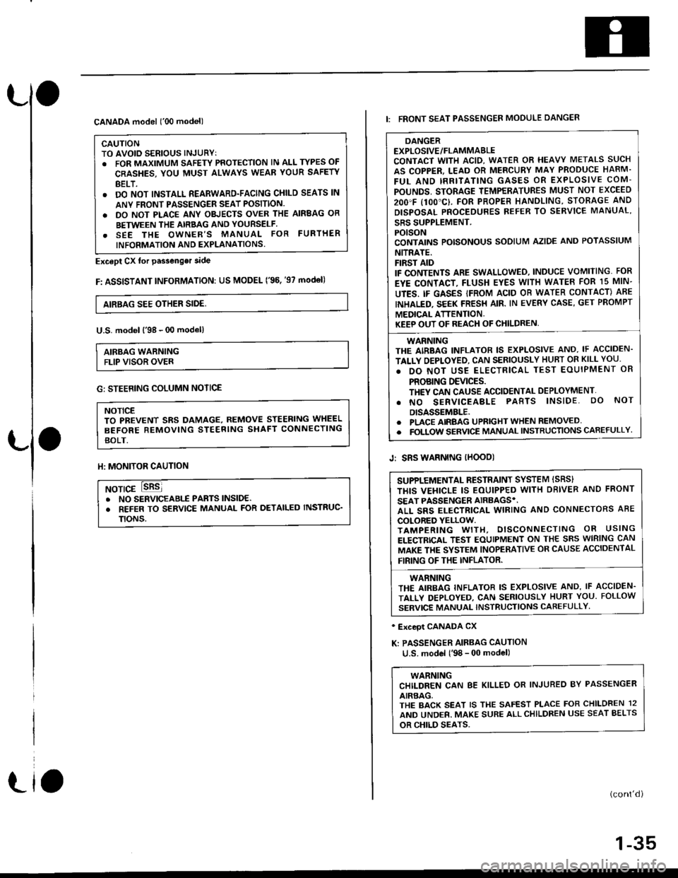
Warning/Caution Label Locations
A: CABLE REEL CAUTION A: '96 -99 model
TO SERVICE MANUAL FOR DETAILED INSTRUC.
TtoNs.
'00 model
ALLATION OF THE SRS CAELE REEL IS CRITICAL TO
THE PROPER OPERATION OF THE SRS SYSTEM. REFER TO
THE SERVICE MANUAL DETAILED INSTALLATION
INSTRUCTIONS.
(cont'd)
1-33
C: DRIVER MODULE OANGER
DANGEREXPLOSIVE/FLAMMABLECONTACT WITH ACIO. WATER OR HEAVY METALS SUCH
AS COPPER. I.EAD OR MERCURY MAY PRODUCE HARMFUL
AND IRRITATING GASES OR EXPLOSIVE COMPOUNDS,
STOBAGE TEMPERATURES MUST NOT EXCEED 2OO'F
I1(x}"CI. FOR PROPER HANDLING. STORAGE AND DISPOS.
AL PROCEDURES REFER TO SERVICE MANUAL. SRS SUP.
PLEMENT.POTSONCONTAINS POISONOUS SODIUM AZIOE AND POTASSIUM
NITRATE.FIRST AID:IF CONTENTS ARE SWALLOWED, INDUCE VOMITING, FOB
EYE CONTACT. FLUSH EYES WTTH WATER FOR 15 MINUTES.
IF GASES {FNOM ACIO OR WATEB CONTACTI ARE INHALED,
SEEK FRESH AIR. IN EVERY CASE, GET PBOMPT MEDICAL
ATTET,ITION.KEEP OUT OF REACH OF CHILDREN.
Br oRIVER MODULE WARNING
WARNINGTHE AIRBAG INFLATOR IS EXPLOSIVE AND, IF ACCIOEN-
TALLY DEPLOYEO, CAN SERIOUSLY HURT OR KILL YOU.. DO NOT USE ELECTRICAL TEST EoUIPMENT oR PROB-
ING OEVICES.THEY CAN CAUSE ACCIDENTAL DEPLOYMENT.o NO SERVICEABLE PARTS lNSlDE. DO NOT
DISASSEMBLE.. PLACE AIRBAG UPRIGHT WHEN REMOVED.. FOLLOW SERVICE MANUAL NSTBUCTIONS CAFEFULLY.
Page 37 of 2189

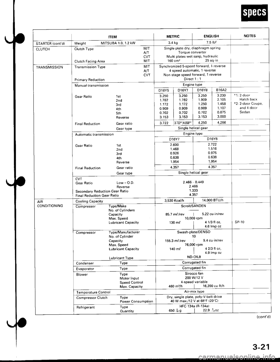
Llo
CANADA model ('00 model)
CAUTIONTO AVOID SERIOUS INJURYT. FOR MAXIMUM SAFETY PROTECTION lN ALL TYPES OF
CRASHES, YOU MUST ALWAYS WEAR YOUR SAFETY
BELT.. DO NOT INSTALL REARWARD-FACING CHILD SEATS lN
ANY FRONI PASSENGER SEAT POSITION.
. DO NOT PLACE ANY OBJECTS OVER THE AIRBAG OR
BETWEEN THE AIRBAG AND YOURSELF.. SEE THE OWNER'S MANUAL FOR FURTHER
INFORMATION AND EXPLANATIONS.
Except Cx tor passenger side
F: ASSISTANT INFoRMATION: US MODEL ('96. '97 mod€l)
AIRBAG SEE OTHER SIDE,
U.S. model l'98 - 00 modell
AIRBAG WARNINGFLIP VISOR OVER
Llo
G: STEERING COLUMN NOTICE
NOTICETO PBEVENT SRS DAMAGE, REMOVE STEERING WHEEL
BEFORE REMOVING STEERING SHAFT CONNECTING
BOLT.
ll: MONITOR CAUTION
NOTICE. NO SERVICEABIf PABTS lNSlDE.. REFER TO SERVICE MANUAL FOR DETAILED INSTRUC'
TtoNs.
DANGEREXPLOSIVE/FLAMMABLECONTACT WITH ACID, WATER OR HEAVY METALS SUCH
AS COPPER, LEAD OR MERCURY MAY PRODUCE HARM.
FUL AND IRRITATING GASES OR EXPLOSIVE COM-
POUNDS, STORAGE TEMPERATURES MUST NOT EXCEED
2OO'F I1OO"C}. FOR PROPER HANOLING, STORAGE AND
DISPOSAL PNOCEDURES REFER TO SERVICE MANUAL'
SRS SUPPLEMENT.POISONCONTAINS POISONOUS SODIUM AZIDE AND POTASSIUM
NITRATE.FIRST AIDIF CONTENTS ARE SWALLOWEO, INDUCE VOMITING. FOR
EYE CONTACT, FLUSH EYES WITH WATEB FOR 15 MIN-
UTES. IF GASES IFROM ACID OB WATER CONTACT) ABE
INHALED. SEEK FRESH AIR. IN EVERY CASE, GET PROMPT
MEDICAL ATTENTION.KEEP OUT OF REACH OF CHILDREN,
WARNINGTHE AIRBAG INFLATOR IS EXPLOSIVE AND, IF ACCIDEN-
TALLY OEPLOYED, CAN SERIOUSLY HUBT OR KILL YOU.
. DO NOT USE ELECTRICAL TEST EOUIPMENT OR
PROBING DEVICES.TH€Y CAN CAUSE ACCIDENTAL DEPLOYMENT'
. NO SERVICEABLE PABTS lNSlDE. oO NoT
DISASSEMBLE.. PLACE AIRBAG UPRIGHT WHEN REMOVED. FOLTOW SERVICE MANUAL INSTRUCTIONS CAREFULLY
I: FRONT SEAT PASSENGER MOOULE DANGER
Jr SRS WARNING IHOOD)
' Exceot CANADA CX
K: PASSENGER AIRBAG CAUTION
u.S. model l'98 - 00 model)
WARNINGCHILDREN CAN 8E KILLED OR INJUREO BY PASSENGER
AIRBAG,THE BACK SEAT IS THE SAFEST PLACE FOR CHILDREN 12
AND UNDER. MAKE SURE ALLCHILDREN USE SEAT BELTS
OR CHILD SEATS.
(cont'd)
1-35
SUPPLEMENTAL RESTRAINT SYSTEM ISRS}
THIS VEHICLE IS EOUIPPED WITH DBIVER AND FRONT
SEAT PASSENGER AIRBAGS'.ALL SRS ELECTRICAL WIRING AND CONNECTORS ABE
COLORED YELLOW.TAMPERING WITH, DISCONNECTING OR USING
ELECTRICAL TEST EOUIPMENT ON THE SRS WIRING CAN
MAKE THE SYSTEM INOPERATIVE OR CAUSE ACCIDENTAL
FIRING OF THE INFLATOR.
WARNINGTHE AIRBAG INFLATOR IS EXPLOSIVE AND, IF ACCIDEN.
TALLY DEPLOYED, CAN SERIOUSLY HURT YOU. FOLLOW
SERVICE MANUAL INSTRUCTIONS CAFEFULLY'
Page 66 of 2189

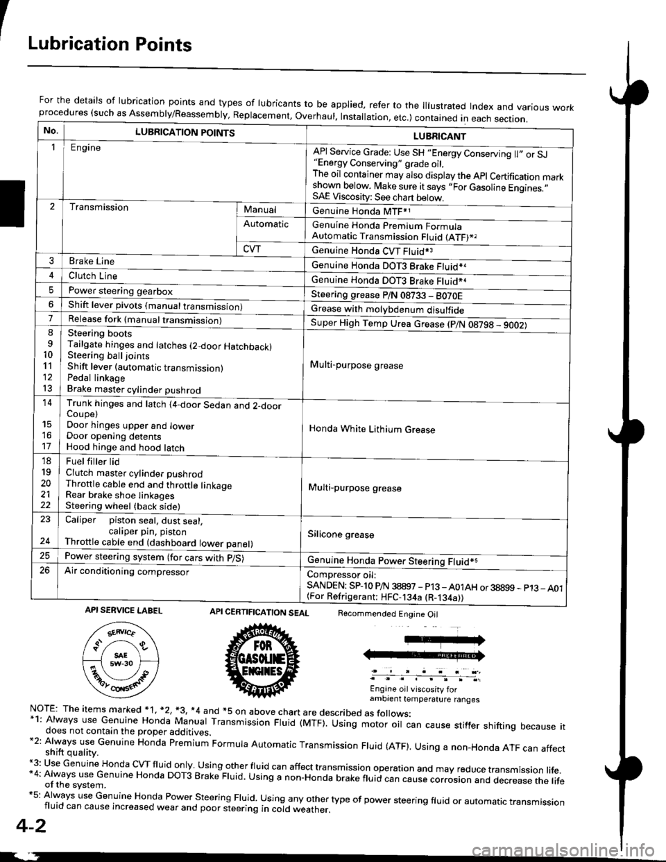
trEM I merntc ENGLISH NorEs
SfAnff n i*nt-i- W"'gf,t MllSUBA r.u, l.z kw r'4 rg
CLUTCHClutch Type
Clutch Facing Area
M/T
CVTM/T
Single plate dry, diaphragm springTorque converterMulti plates wet sanP, hYdraulic160 cm,25 sq in
Synchronized 5-speed forward, 1 reverse
4 speed automatic, 1 reverse
Non stage speed forward, 1 reverse
Direct 1 : 1
TRANSMISSIONTransmission Type
Primary Reduction
M/TArrCW
Manualtransmission
Gear Ratio 1st2nd3rd4th5thReverse
Final Reduction Gear ratio
Gear tYPe
Engine type
D16Y5 | D16Y7 D16Y8 I 81642
3.2501.1821.1120.9090.7023.153
3.2501.1821.1120.9090.7023.153
3.2501.9091.2500.9090.1023.153
3.2302.1051.4581.1070.8753.000
*1:2 doorHatch back+2r 2-door Coupe,and 4 doorSedan
3.122 13.122"11.053" 1 4.250 | 4.266
Single helicalgear
Engine type
D16Y7 | D16Y8Automatic transmission
Gear Ratio 'lst
2nd3rd4thReverse
Final Reduction Gear ratio
Gear tYPe
2.6001.4680.9260.6381.954
2.122
0.9750.6381.954
1.3514.357
cwGear Ratio Low - O.D.Reverse
Secondary Reduction Gear Ratio
Final Reduction Gear Ratio
2.466 0.4492.4661.3334.357
AIRCONDITIONING
Cooling Capacity3,530 Kcal/h14,000 BTU/h
Compressor Type/MakeNo. of CYlindersCaPacitYMax. SpeedLubricant CaPacitY
Scroll/SANDEN
85.7 m//rev 5.22 cu inkev10,000 rpm130 mf 41l3tl oz.
| 4.6 imp ozsP,10
Compressor Type/ManufacturerNo. of CylinderCapacityMax. SpeedLubricant CaPacitY
Lubricant TYPe
Swash-plate/DENso10155.3 mf /rev 9.4 cu_in/rev76,000 rpm140 mf | 4 2l3fl oz,I 4 9lmp ozND'OIL8
Condenser TypeCorrugated fin
Evaporator TyPeCorrugated fin
Elower TyPeMotor InputSPeed ControlMax. CaPacity
Sirocco fan200w112v4 speed variable460 m3/h 16,200 cu ft/h
Temperature Control
Compressor Clutch TyPePower ConsumPtionDry, single plate, PolY-V'belt drive40 W max./12 V at 68'F (20'C)
Refrigerant TyPeouantity
HFC 134a (R'134a)
650 gos | 22.9 isoz
(cont'd )
4 . J-Z I
Page 72 of 2189

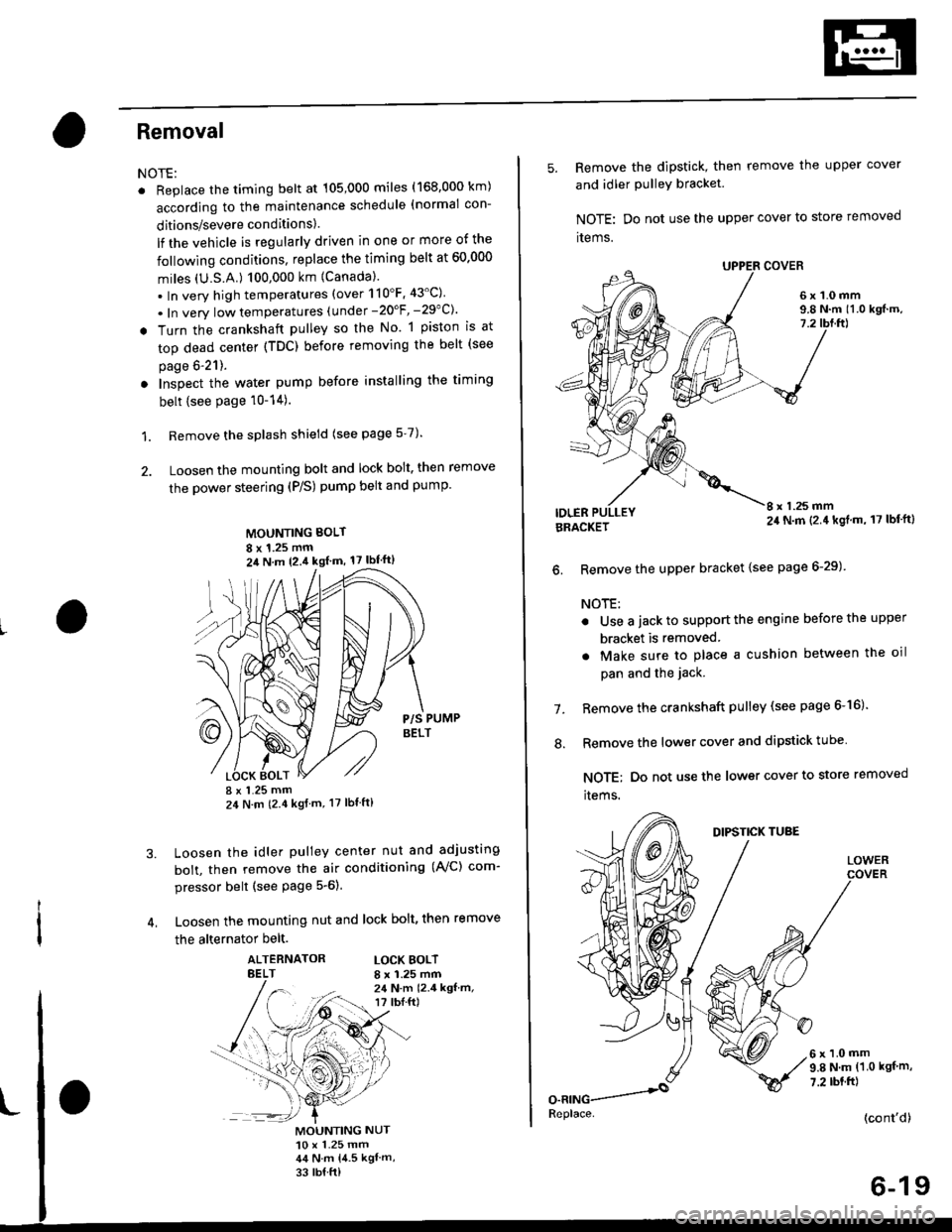
ILubrication Points
For the details of lubrication points and types of lubricants to be applied, refer to the lllustrated Index and various workprocedures (such as Assembly/Reassembly, Replacement, Overhaul. Installation, etc.) contained in each section.
No.LUBRICATION POINTS
Engine
LUBRICANT
"Energy Conserving" grade oil,The oil container may also display the Apl Certification markshown below. Make sure it says ,,For Gasoline Engines.,,SAE Viscosity: See chart below,
I
TransmissionManualGenuine Honda MTF*1
Genuine Honda Premium FormulaAutomatic Transmission Fluid (ATF)*,
Genuine Honda CVT Fluid*3
Genuine Honda DOT3 Brake Fluid*a
Automatic
CVT
3Brake Line
ClL,tci t""e4
I
Genuine Honda DOT3 Brake Fluid*aPower steering gearboxSteering grease P/N 08733 - BO70EShift lever pivots (manual transmission)Grease with molybdenum disulfide7-:ti
9
10'l'l
l3
14
't7
18
19
20
2122
Release fork (manual trancmi
Shift lever (automatic transmission)Pedal linkageBrake master cylinder pushrod
Super High Temp Urea crease (p/N 08798 - 9OO2)
i Multi-purpose grease
I
I
Honda White Lithium Grease
Multi-purpose grease
Silicone grease
@
Trunk hinges and latch (4-door Sedan and 2-doorCoupe)Door hinges upper and lowerDoor opening detentsHood hinge and hood latch-FUet T ter ttd
Clutch master cylinder pushrodThrottle cable end and throttle linkageRear brake shoe linkagesSteering wheel (back side)
23
E-
Caliper piston seal, dust seal,caliper pin. pistonThrottle cable end (dashboard lower panel)
Power steering system (for cars with p/S)
Air conditioning compressorComDressor oil:SANDEN: SPlo P/N 38897 - p13 -A01AH or 38899 - p13_ A01{For Refrigerant: HFC-134a (R-134a))
CERTIFICATION SEAL
ffi
NorE: The items m arked * 1, *2, +3, *4 and +5 on above chan are described as folows:*1: Always use Genuine Honda Manual Transmission Fluid (MTF). Using motor oil can cause stiffer shifting because itdoes not contain the proper additives.*2: Always use Genuine Honda premium Formula Automatic Transmission Fluid (ATF). Using a non-Honda ATF can affectshift quality.+3: Use Genuine Honda cVTfluid only usingotherfluid can affect tra nsmission operation and may reduce transmission life.*4: Always use Genuine Honda DoT3 Brake Fluid. Using a non-Honda brake fluid can cause corrosion and dec.ease the lifeof the svstem.*5: Always use Genuine Honda Power steering Fluid. using any other type of power steering fluid or automatrc transmissionfluid can cause increased wear and poor steering in cold weather.
4-2
Recommended Engine Oil
Engine oil viscosity forambrent temperature ranges
API SERVICE LABEL
Page 97 of 2189

8. Remove the intake air duct and air cleaner housing.
D16Y, ongino:
a. Remove the resonator and intake air duct.
6x1.0mm9.8 N.m (1.0 kgt m, 7.2 lbf.tt)
INTAKE AIR
Disconnect the intake air tempsrature (lAT) sen-
sor connector, then r€move thg air cleaner hous-
Ing.
6x1.0mm9.E N.m (1.0 kgtm, t.2lbtft,AIR CI."EANERHOUSING
IAT SENSORCONNECTOR
016Y5, Dl6Y& 815A2 engin€sl
a. Disconnect the IAT sensor connector, then
remove the intake 8ir duct and air cleaner hous-
Ing.
6x1.0mm9.8 N m {1.0 kgtm, 7.2 lbl'ft)
AIR CITANERHOUSING
INTAKE AIRDUCT
IAT SENSORCONNECTOR
9. Disconnect the engine wire harness connector on
the left side of the engine compartment.
(cont'd)
5-3
Page 130 of 2189

Removal
NOTE:
. Replace the timing belt at 105,000 miles (168.000 km)
according to the maintenance schedule (normal con-
ditions/severe conditions).
lf the vehicle is regularly driven in one or more of the
followlng conditions, replace the timing belt at 60.000
miles (U.S.A.) 100,000 km {Canada).
.In very high temperatures (over 110'F.43'C)
. In very low temperatures (under -20'F, -29"C)'
! Turn the crankshaft pulley so the No. 1 piston is at
top dead center (TDC) before removing the belt (see
page 6'21).
. Inspect the water pump before installing the timing
belt {see Page 10-14).
1. Remove the splash shield (see page 5-7).
2. Loosen the mounting bolt and lock bolt. then remove
the power steering (P/S) pump belt and pump
MOUNTING BOLT
8 x 1.25 mm2il N m 12.4 kgl m, 17 lbf'ft)
P/S PUMPBELT
I x 1.25 mm24 N m (2.4 kgf m, 17 lbt ft)
Loosen the idler pulley center nut and adjusting
bolt, then remove the air conditioning (AVC) com-
pressor belt (see Page 5-6).
Loosen the mounting nut and lock bolt, then remove
the alternator belt.
ALTERNATORBELTLOCK BOLTI x 1.25 mm24 N.m 12.4 kgf.m,r? tbI.ft)
3.
MOUNTING NUT10 x 1.25 mm44 N.m 14.5 kgl m,
33 rb{ ft)
5. Remove the dipstick, then remove the upper cover
and idler PulleY bracket
NOTE: Do not use the upper cover to store removed
items.
6x1.0mm9.8 N.m 11.0 kgf.m,7.2
IDLERI x 1.25 mm24 N.m (2.4 kgl.m, 17 lbf'ft)BRACKET
6. Remove the upper bracket {see page 6-29)
NOTE:
. Use a jack to support the engine before the upper
bracket is removed
. Make sure to place a cushion between the oil
pan and the jack.
Remove the crankshaft pulley (see page 6-16).
Remove the lower cover and dipstick tube
NOTE; Do not use the lower cover to store removed
items.
1.
.'.
DIPSTICK TUBE
LOWER
6x1.0mm9.8 N.m (1.0 kgf m,
7.2 rbt.ft)
(cont'd)
6-19
Replace.
Page 138 of 2189

Removal
Engine removal is not required for this procedure
!!!s@ Make sure iacks and salety stands are
f ta"eata"ea propetty and hoist brackets are attached to the
correct positions on the engine.
CAUTION:
. Use tender covels to avoid damaging painted sul-
faces.
o To avoid damage, unplug the wiling connectors
carefully while holding the connector portion to
avoid damage.
. To avoid damaging the cylinder head, wait until the
engine coolant temperature drops below 100"F
{38"C} before loossning the tetaining bolts.
NOTE:
o Mark all wiring and hoses to avoid misconnectlon
Also, be sure that they do not contact other wiring or
hoses, or interfere with other parts.
. Inspect the timing belt before removing the cylinder
h ead.
. Turnthe crankshaft pu lley so that the No. lpistonisat
top dead center (see Page 6-21)
'1. Disconnect the negative terminal from the battery'
Drain the engine coolant (see page'10-7).
a Remove the radiator cap to speed draining.
Remove the intake air duct and air cleaner housing
(see page 5 3).
Remove the mounting bolt and lock bolt. then
remove the power steering (P/S) pump belt and
pump (see page 5'5).
Loosen the idler pulley center nut and adjusting
bolt' then remove the air conditioning (A'lc) com-
pressor belt (see Page 5-6).
Loosen the mounting nut and lock bolt. then
remove the alternator belt (see page 6-19).
Remove the P/S pump bracket (see page 5-12).
3.
4.
2.
6.
1.
8. Remove the throttle cable by loosening the locknut,
then slip the cable end out of the throttle linkage
NOTE:
. Take care not to bend the cable when removing it
Always replace any kinked cable with a new one
. Adjust the throttle cable when installing (see sec-
tion 1 1).
D16Y7 engine:
Dl6Y5, Dl6Y8 engines:
THFOTTLECABLE
(cont'd)
6-27
LOCKNUT
CABLE
Page 140 of 2189

13. Remove the upper radiator hose' heater hose and
water bYPass hose
WATEREYPASSHOSEUPPERRADIATORHOSE
14.
HEATERHOSE
Remove the engine wire harness connectors and
wire harness clamps from the cylinder head and the
intake manifold.
o Four fuel injector connectors
. Engine coolant temperature (ECT) sensor con-
nector
a
a
a
ECT switch connector
ECT gauge sending unit connector
Throttle position sensor connector
Manitold absolute pressure (MAP) sensor con-
nector
Primary heated oxygen sensor (primary HO2S)
connector
Secondary heated oxygen sensor (secondary
HO2S) connector (D16Y7 engine)
Exhaust gas recirculation (EGR) valve lift sensor
connector (D16Y5 engine)
. VTEC solenoid valve connector (Dl6Y5, D16Y8
engrnes)
. VTEC pressure switch connector (D16Y5. D16Y8
engrnes,
. ldle air control (lAC) valve connector
15.Remove the spark plug caps and distributor from
the cylinder head.
Remove the uPPer bracket.
NOTE:
. Use a jack to support the engine before the
upper bracket is removed.
. Make sure to place a cushion between the oil
pan and the jack.
12 x 1.25 mm
74 N.m {7.5 kgf m.
sil lbl.ftl
UPPERBRACKET
'17. Remove the cylinder head cover'
CYLINDERHEAD COVER
(cont'd)
6-29