Page 1817 of 2189

Contents
How to Use This Manual ICircuit Schematics (see Circuit Index)Fuse/Relaylnformation 6Ground-to-Componentslndex 6-6ComponentLocationPhotooraohs 201Conriector Views 202
Circuit Index
Accessory power socket 155Air conditionerAir delivery'96198 models 61'99-'00 models 61-2Blower controls'96198 models 60'99100 models 60-1Compressor controls 62Fans 63Anti-lock brake system (ABS) 44A/T gear position indicatorCVT 89All except CVT 89-1Automatic transmission controlsAll '96-'98 models except CVT and GX 39All '99100 models except CVT 39-8All GX models 39-8'96-'�98 CVT 39-4'99100 cw 39-12Back-up lightsCoupe and Sedan 110Hatchback l'10-1Brake lightsAll Coupes and'96-'98 Sedans 110-15'99-'00 Sedans 110-16Hatchback 110-17Brake system indicator light'96198 models 7'1'99100 models 71-1Ceiling light 114-3Charging system 22Condenser fan 63Console lights 114Cruise control 34Dash lights 114Daytime running lights 110- 13Engine coolant temperature gauge 81-1Fog lights 110-10Front parking lights 110-2Fuel gauge 81-1Fuse/relay boxUnder-dash 6Under-hood 6-4Underhood ABS 6-3Gauges 81Ground distribution 14Ground-to-Componentslndex 6-6Hazard warning lightsAll except '99100 Sedans 110-6'99100 Sedans 110-8Headlights 110-12Headlight switch 100Heater - See Air ConditionerHorn'96197 models 40'98 model 40-1'99100 models 40-2lgnition key reminder 73lgnition systemAll '96198 models except Dl685 20All '99100 models except D16Y5 with Mn 2O-2All D1685 engines 20-2'99-'00 D 16Y5 with M/T 20
lndicators 80Integrated control unit 70lnterlock systemAll except'96J98 CVT 138'96198CVT 138-1License plate lightsAll Coupes and '96-'98 Sedans I l0-3'99100 Sedans 1 10-4Hatchback 110-5Low fuel indicator light 74Moonrool'96197 models |22'98-'00 models 122-1Odometer 81Oil pressure indicator light 80-3Power distributionBattery to ignition switch, fuses, and relaysFuses to relays and components 10-2Power door locksAll models without keyless entry 130'96-'98 models with keyless entry 130-2'99100 models with keyless entry 130-12Power mirrorsWithout detogger 141With defogger '141-2
Power windows 120Programmed fuel injection system (PGNr-Fl)All '96-98 models except D1685 23All '99-'00 models except D16Y5with M/T and D1685 24All D1685 engines 25'99100 D16Y5 with M/T 23Radiator fan 63Rear window defogger'96-,98 models 64'99100 models 64-1Seat belt reminder 73Security system'96.'98 USA HX, LX, EX 133'96-'98 Canada EX, Si 133'99TOO USA HX, LX, EX, DX.V Si 133-4'99100 Canada EX, Si 133-4All CX and DX models 133-8Speedometer 81Starting systemA./T (All except Dl685) 21A"/r (D16Bs) 21-1Manualtransmission 21-2Slereo sound system 150Supplemental rastraint system (SRS) 47Tachometer 81TailliqhtsAllboupes and'96-'98 Sedans 110-3'99100 Sedans 1 10-4Hatchback 110-5Trunk light 114-3Turn signal lightsAll except'99100 Sedans 110-6'99-'00 Sedans 1 10-8Vehicle speed sensor (VSS) 33Wiper/washerFront 91Rear 92
10
Page 1890 of 2189
PGM-FI (All '9e'98 Models except D1685; '99-'00 D16YS with M/T)
- D16Y8 Engine
I
I
-t---"",t ;
ii hffi- i ffis* #""r, i"[' | (PTAN6 , gCC2l fips)'L-------4-----
i -:l i ,,,rt[
"'[ D2
lllHd,..--"ffi[il
iffi;',::l-l' anv ll '97 model: allCoubes, I' au I calitornia Sedan I
i n":, *t,*%,nof
'o0"" "",
lf1 fr3::fj* |
:"*iu,.'o ' lJ l;'F#F. I
id[fr?4;" i
'[ i
i +l L'i':----i ---I- - - - - -::'
iko,*o* [U!3v'0" I
rrar) ' lniczdt I
6i?----i''-v------J
BEO/^YEL
sensor nput(ECo
NTsensol lnpdlnqrr
BA /BLK).l
.a
II
t
k
PRIMARYHEATEDOXYGENSENSOR(H02S)
c123
cr23PHOTO 42
_1
ALX
ALK
-i
INTAKEAIRTEMPER.ATUREOAT)SENSORPHOTO 15
E33"ln'*' l-1-l
g.:;'$;lfj
H
t
,{
LT GA
2
GNN/BLK
8!(7YEL
c 5(Terml-nala8n4)
vtEw 38
GRN/BIK
Dll
BLI(AVHT
a ' sSfl, *SffT3,. {
I grourd heater'clntrot r\
t!IL------- -------
23-10
Page 1893 of 2189

FED/YEL! il'Jlilli:Distribulon,
i
!aa
il-
"""r"a^ Itl
+9,1:1o,,,
Fromnext page.FI
t
H
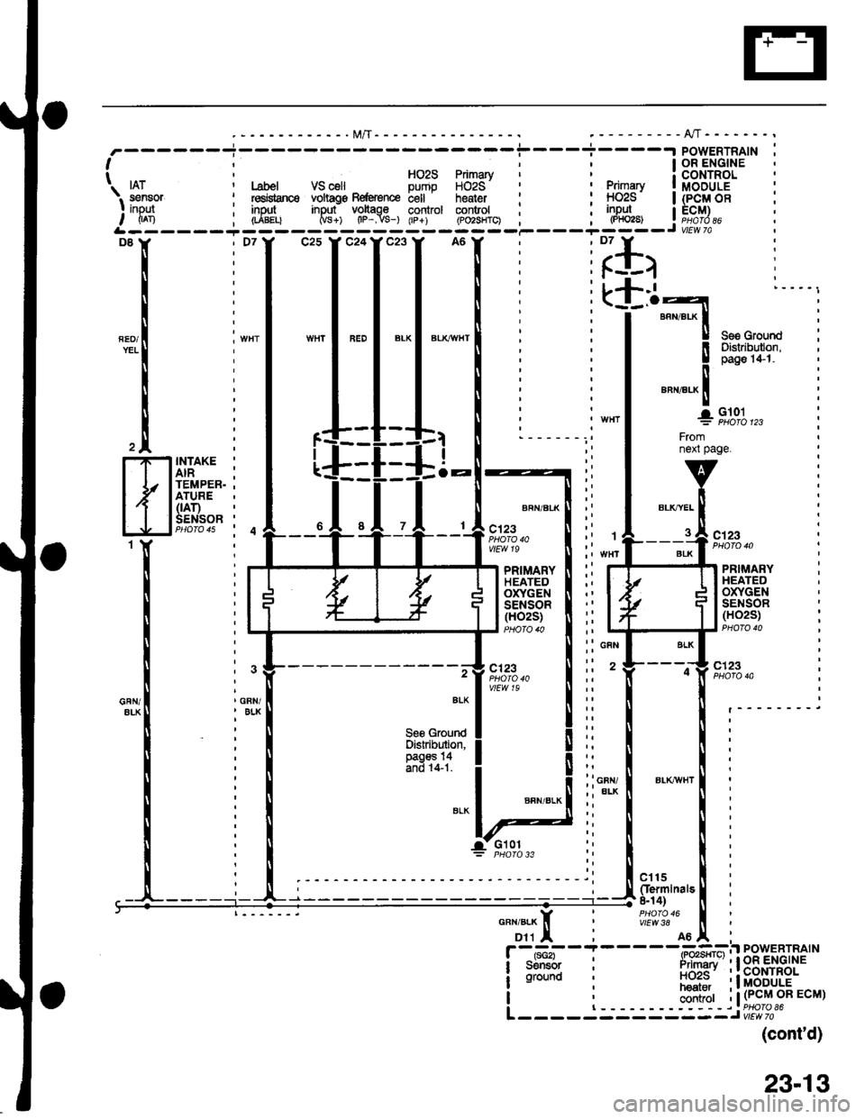
INTAKE '
AIR ;TEMPER. .ATURE(rAr)SENSOR 'PHO|O 4s i 4
BRN/BLK
c123PHO|O 40vlEw 19c123
PRIMARYHEATEDOXYGENSENSOR(HO2S)
PRIMARYHEATEDOXYGENSENSOR(H02S)
-- -.-g c123,7 ,t1":.," I :: ' t---o} "",'"?",vtEw 19ErKl i:: ll [ .________i
leggtqe"d! ll:: I | :Distribution. I I ,; ll ll :
ffi31i1'1 ! lii i l:i ioty I er-rcrwr | :
:i*-! ! i
:i ! ! i
-a-- Glol:i I I :"uu,
--------t; igul,.[l :g.ili'""'"t i
11TI i
#?:?.'A6tr
i
F -tt-*i - I - - - -(-Po"GFil PowERTRAIN
i sdltGr i irimari' ' I oR ENGINE
! ;il;n i nciis' 'lcortnor
hear.r 'l MODULE| , haat.. .tMvuuLE
I ; ;;ii;r i | (PcM oR EcM)
I | ------riPHOfOS6L ------ - ------J vtae al
(cont'd)
. I OR ENGINE' HOzS Primary i CONTROLI fruzs Fflmary a c(JNIHor Label VS celt Dumo HOzS' ' , primary | MOOULE
i l"dqanc6 vohags Befe{ence bell . heater i : !-1029 | (p-Q!/| OB: red$snce voltag€ Beftrence c€ll heater ' : HOzS | (PCM OB: insJt input voltage control control ; ; inpul I ECM), (rABELt Ms+) tlP-.vs-) (rp+) (Po2sHrc) ; , l"Y_ j r;!J?.*----i---
i
-l "*
I'*l*'l
*l
i iillirlr I
:L+.1 l----,. (_l_.o-l
: I annar-x | :
: I I see Grourd
23-13
Page 1903 of 2189
PGM-FI (All '99-'q) Models except D16Y5 with M/T and D1685) (cont'd)
- Dl6Y7 Engine
ct6
(
k
GRN
GRN/ALK
II
)
-l.a
FUELTANKPRES-SURESENSOR(See S/M1
BLK
GFN/BLK
GNN/BLK
6
GAN/8LX
8
GFiI/BIK
tis3 :INTAKEAIRTEMPER-ATURE(|AT)SENSOR
PRIMARYHEATEDOXYGENSENSOR(HO2S)
c'123
c123
cs68PHOTO 103
c401
vtEw 40
ct31
vlEvt S9
FffiflH
{
r,Bi".'#
H
r{
t
f 5:o#'""'"n
rtrt
BLK
at
It
lFueltan* TP \lpr€asura Rg{grsncs ssnsor ECT IAT Primary IF€nsor inpJt voltago input sensor input sensor inpul HO2S inout I| (rt^xn Naca Crpsr lscn - -- 1-ran -- -(p,ioi3i-- ,L------- -----J
BLKT^YEL
clt5(Ierminals 8-14)
vlEw38
contaol
24-8
Page 1905 of 2189
PGM-FI (All '9S"00 Models except D16Y5 with M/T and D1685) (cont'd)
- Dl6Y8/816A2 Engines
c123PHO|O 133
)
t
II
r
k
'l
ir
c27
3 crsoI (Termlnals
ll 18-20)
li#?t?,"
It
ll
I ".r,".*ll
lt
ll
I
lt
lL___3
H'I
t
I
I
I Rrol tankipressure Fobrsnco: ssnsot inDul volt4€| (Pr^No 0ccaL-- --- - -*'I
:*I-.
;iH$ffi1
l-Flitii!
lJri li::#'":l
"oil ??$j
"rt
*tinr+- l+-
*'.,9s,g';,, f
-:i*<'lrp !
-I$"";*", o"",".,. I"rnLi':______I
ALK
INTAKEAIRTEMPER.ATURE(rAr)SENSORPHO|O 15
PRIMARYHEATEDOXYGENSENSOR(H02S)PHOTO 13iF}$iH
:{
F#-H
{
c123PHOTO 133
LT GFII
2
ORN/ALX
c1r5(Iermlnalr8-14)PHOfO 16
I
I
I
I
24-10
Page 1914 of 2189
-.t POWERTRAIN
lcoNTRoL
Fuel I MODULE
\. . -,.^-- p{sssure
I llglllTP-. . sansor sensor .s€nsor i;ir*,o; sensor_rnpul input input input :I nFa (PF2) GcD i|An IrL------ --------Jc13 I' c14Y c26
FUELTEMPERATURESENSOR
Fromfacingpage.
v
!
_l
Fromnenpage.
vi
GFN/BLK lI
i
EG-f
flltur'ffi
,{J
ENGINECOOLANTTEMPERATURE(Ecr)SENSOR
INTAKEAIRTEMPERATURE(rAr)SENSOR
c't 15(ferminals &14)
vtEw 38
(cont'd)
25-7
Page 1957 of 2189

- How the Circuit Works
Battery voltage is supplied through tuse 56 to the
A,/C compressor clutch r€lay contacts at all times.
With the ignition switch in ON (ll), vollage is applied
to the coil of the A,/C compressor clutch relay
through fuse 17. When you push the A,/C switch
ON, and the heater fan switch is in position | , 2, 3,
or 4, a "ground" input is provided to the engine
control module (ECM) or powertrain control module
(PCM) through the l'lC thermostat and the l'lC
pressure switch.
The A,/C compressor clutch relay is grounded by the
engine control module (ECM) or powertrain control
module (PCM). When energized, the A'lC
compressor clutch relay allows battery voltage to
turn on the A,/C comDressor clutch.
The A,/C ON indicator light comes on when the A,/C
system is requested.
A,/C Thermostat
The A'lC thermostat is located on the evaoorator
housing. The A,/C thermostat turns off the A,/C
compressor clutch if the temperature at the
evaporator goes below 3'C (37'F). This prevents
condensation from freezing on the evaporator fins
and blocking the air delivery into the passenger
compartment. The blower motor will keep running
when the sensor turns off the comDressor.
A,/C Pressure Switch
The fuC oressure switch is located in the condenser
outlet line where refrigerant is in a high
temperature/high pressure liquid state. The switch
will sense abnormally high or low pressure, and
open the circuit. This removes ground, and the
compressor will stop running.
Thermal Protectot
The thermal protector, located on the A,/C
compressor, opens and turns the compressor off if it
senses high temperature. Once the compressor
cools, the switch will close and the compressor will
begin running again.
Refer to the Service Manual (Section 22,
Air Conditioning) for specific tests or
troubleshooting procedures.
62-3
Page 1961 of 2189

- How the Circuit Works
Radiator Fan
Voltage is provided at all times to the radiator fan
relay (contacts) through fuse 57. With the ignition
swilch in ON (ll), voltage is provided to the coil of
the relay through luse 17.
The radiator tan relay can be grounded through
either the engine coolant temperature switch or the
engine control module (ECM) or powertrain control
module (PCM).
The engine coolant temperature switch grounds
the radiator fan relay (coil) when the engine
coolant temperature exceeds 199'F (83'C). The
switch opens when coolanl temperature
decreases 3'- 8'C.
Condenser Fan
Voltage is provided at all times to the condenser fan
relay (contacts) through fuse 56. With the ignition
switch in ON (ll), voltage is provided to the coil of
the relay through fuse 17. When you push the A'lC
switch and put the heater fan switch in 1, 2,3, o( 4
position, the ly'C thermostat comes on, the
condenser fan relay energizes, and the condenser
fan motor runs.
A,/C Thermostat
The A,/C thermostat is located on the evaporator
housing. The A,/C thermostat tums off the A/C
compressor clutch if the temperature at the
evaporator goes below 3'C (37'F). This prevents
condensation from freezing on the evaporator fins
and blocking the air delivery into the passenger
compartment. lf the temperature goes below 3'C
(37"F) tuming off the Ay'C thermostat, ground will be
removed from the condenser fan relay. This will
deenergize the relay and remove voltage from the
condenser fan motor causing the fan to stop running.
Reter to the Service Manual (Section 23, Eleckical)
for specific tests or troubleshooting procedures.
63-3