Page 52 of 2189

Unit of length: mm (in)
Fuel and Emission - Section
MEASUREMENTSTANOARO (NEW)
260 310 (2.7 - 3.2, 38 - 46)
260 - 310 (2.7 - 3.2, 38 - 46i
260 - 310 (2.7 - 3.2, 38 - 46)
210 - 320 Q.A - 3.3, 40 - 47 1
45 {11.9, 9.9)
M/T (neutral) I A/T or C\.T (lE or fd positioni
Fuel paessure
regulator
Pressure wilh fuel pressure regulator vacuum hose
disconnected kPa (kgvcm'�, Psi)D16Y5D 16Y7D16Y881642
FueltankCapacity I (US gal, lmp gal)
E ngineldle speed rpm
016Y5D16Y7D16Y8816A2
u.s.A.CanadaU,S,A.Canada
670 1 506701 50670150700 t 50
7501 507501 507501 50
700 t 50700 I 507001 50750150750 r 50
ldle CO %0.1 max.
Clutch - Serrtion 12
MEASUREMENTSTANDARD {NEWI I SERVICE LIMIT
Clutch pedalPedal height to floor
StrokePedal play
Disengagement height to floorto carpet
16s (6 1/2)130 140 (5 1/8 5 1/2)
12 -21 t1l2 - 13/16183 (3 1/4)44 (1 3/4) min. Reference
FlywheelClutch surface ruoout
Rivet head depthThickness
0.05 (0.002) max.0.15 (0.006)
Clutch disc1.3- 1.9 (0.05 - 0.07)
8.5 - 9.1 (0.33 - 0.36)
0.2 {0.01)5.5 (0.22)
Pressure plateWarpageDiaphragm spring fingers alignment
0.03 (0.001) max0.6 (0.02) max
0.15 (0.006)
1.0 (0.04)
Lro
3-7
lfllHlllllllllrltllli[
Page 155 of 2189

Valves
Camshaft/Rocker Arms and
Camshaft Seal/Pulley
Installation (cont'd)
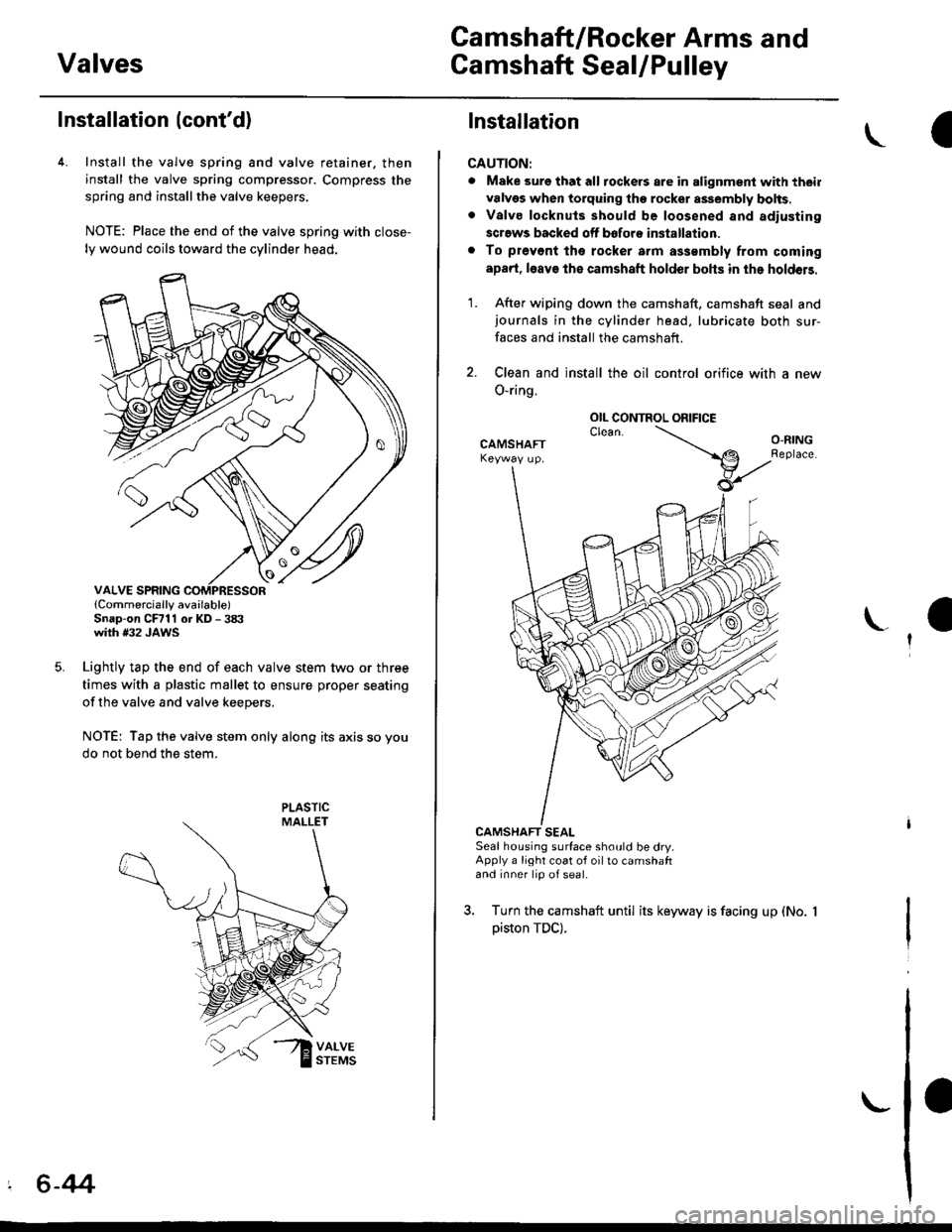
4. Install the valve spring and valve retainer. then
install the valve spring compressor. Compress the
spring and installthe valve keepers.
NOTE: Place the end of the valve spring with close-
ly wound coils toward the cylinder head.
lCornmercially available)Snap-on CFrll or KD - 3tX'with #32 JAWS
Lightly tap the end of each valve stem two or three
times with a plastic mallet to ensure proper seating
of the valve and valve keepers.
NOTE: Tap the valve stem only along its axis so you
do not bend the stem.
' 6-44
Installation
CAUTION:
. Make sure that all tockers are in alignment with their
valvgs when torquing the rocket assembly bolts,. Valve locknuls should be loosened and adiusting
screws backed off bofore installation.
. To prevont tho rocker arm a$smbly from coming
apad, l6av€ the camshaft holder bohs in the holdeB.
1. After wiping down the camshaft, camshaft seal andjournals in the cylinder head, lubricate both sur-
faces and install the camshaft.
2. Clean and install the oil control orifice with a new
O-ring.
CAMSHAFT SEALSeal housing surface should be dry.Apply a light coat of oil to camshaftand inner lip of seal.
3. Turn the camshaft until its keyway is facing up (No.
piston TDC).
OIL CONTROL ORIFICE
Page 203 of 2189

lllustrated Index
(cont'd)
NOTE: New rod bearings must be selected by matching connecting rod assembly and crankshaft(see page 7,11).identification markings
Lubricate all internal parts with engine oil duringreassembtv.
PISTON INSTALLATION DIRECTION:
EXHAUST
4\/=\6\z\
\e/!rqrf/
INTAKE
PISTON RINGSReplacement. page 7-20Measurement, pages 7 20 andj-21Alignment, page 7-21
PISTON PINRemoval, page 7,17Installation, page 7-18Inspection, page 7,19
CONNECTING RODEnd play, page 7-8Selection, page 7,18
CONNECTING RODBEARINGSClearance, page 7 11Selection, page 7-11
CONNECTING ROD BEARING CAPInstallation, page 7-23NOTE: lnstall caps so thebearing recess is on thesame side as the recessin the rod.
PISTONInspectron, page 7-15NOTE: Betore removing the piston, inspect thetop of the cylinder bore for carbon build-up orridge. Bemove ridge if necessary, page 7-13
ENGINE BLOCKCylinder bore inspection, page 7-16Warpage inspection, page 7,'16Cylinder bore honing, page 7,17
Inspect top of each cylinder borefor carbon build-up or ridgebefore removing piston.Remove ridge if necessary, page 7-13
CONNECTING ROD CAP NUT816A2 €ngin6:9 x 0.75 mm{0 N.m (4.1 kgt m, 30 tbf.ftlD16Y5, Dl6Y7. D16Y8 engines:8 x 0.75 mm3l N.m {3.2 kg{.m,23 tbt.fr)Apply engine oiltothe bolt threads.NOTE: After torquing each bearingcap, rotate crankshaft tocheck for binding.
7-6
Page 211 of 2189

Crankshaft
Inspection
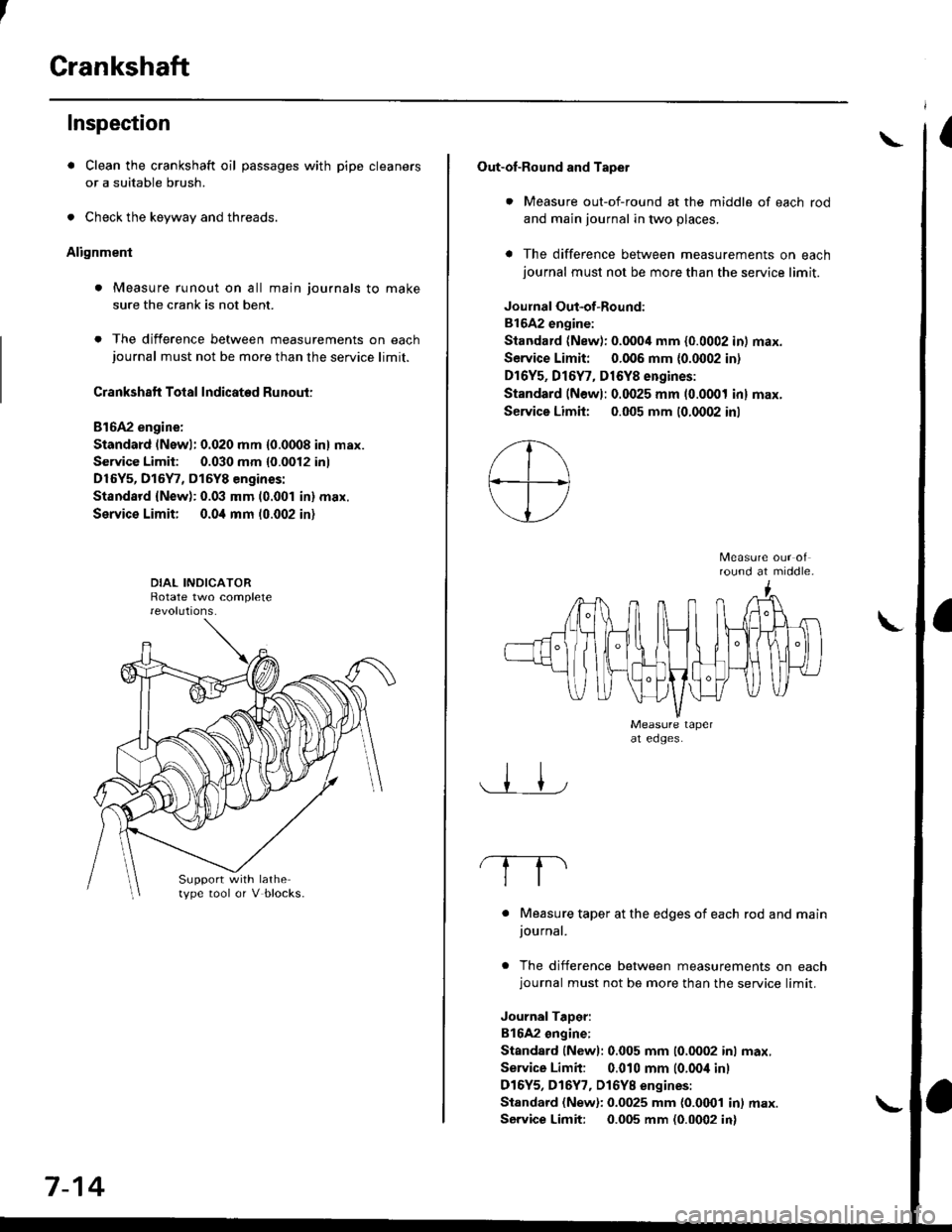
. Clean the crankshaft oil passages with pipe cleaners
or a suitable brush.
. Check the keyway and threads.
Alignment
. Measure runout on all main journals to make
sure the crank is not bent.
. The difference between measurements on eachjournal must not be more than the service limit.
Crankshaft Total Indicated Runout:
Bl6A2 engine:
Standard (Newl: 0.020 mm {0.0008 in} max.
Service Limit: 0.030 mm {0.0012 inl
D16Y5, D15Y7, D15Y8 engines:
Standsrd {New): 0.03 mm (0.001 in} max.
Service Limit; 0.0i1 mm 10.002 in)
Support with lathetype tool or V blocks.
7-14
Out-of-Round and Tapet
. Measure out-of-round at the middle of each rod
and main journal in two places.
a The difference between measurements on eachjournal must not be more than the service limit.
Joulnal Out-of-Round:
81642 engine:
Standard (New): 0.0004 mm {0.0002 in) max.
Service Limit: 0.006 mm {0.0002 in)
Dr6Y5, Dl6Y7, D16Y8 engines:
Standard (Newl: 0.0025 mm (0.0001 inl max.
Service Limh: 0.005 mm (0.0002 inl
round at middle.
. Measure taper at the edges of each rod and mainjournal.
. The difference between measurements on eachjournal must not be more than the service limit.
JournalTaDer:
B16A2 ongine:
Standard lNewl: 0.005 mm (0.0002 inl max.
Service Limit: 0.010 mm (0.00i1 inl
D16Y5, D16Y7, Dl6YB engines:
Standard (New): 0.0025 mm {0.0001 in) max.
Service Limit: 0.005 mm (0.0002 in)
\
Page 218 of 2189
Ring-to-Groove Clearance
After installing a new set of rings, measure ring-to-
groove clearances:
Top Ring Clearance
Standard (New):
B16A2 angine:
0.045 - 0.070 mm (0.0018 - 0.(X128 in)
Dl6Y5, Dt6Y7, Dl6Y8 engin€s:
0.035 - 0.060 mm {0.0014 - 0.002'l in)
service Limit: 0.13 mm (o.fixi in)
Second Ring Clearance
Standard lNow):
B16A2 engine:
0.0/t0 - 0.065 mm (0.0016 - 0.0026 in)
Dl6Y5, D16Y7, D16Y8 onginos:
0.030 - 0.055 mm (0.(X)12 - 0.0022 in)
Sewica Limh: 0.13 mm (0.005 io)
.,o
Alignment
1. Installthe rings as shown.
NOTE: The manufacturing marks must be facing
upward.
SECOND RING (Darkl
Piston Ring Dimsnsions:
Unit mm (in)
Unit mm (in)
TOP RING (Chrome)
t----T f
lB
t---f_-L
A
Top Ring (Standard)
Second Ring (Standard)
B
Bl642 engine3.1 (0.12)1.0 (0.04)
D16Y5, D16Y7,
D16Y8 engines2.6 (0.10)1.0 (0.04)
B
816A2 engine3.3 (0.13)1.2 (0.05)
D16Y5, D16Y/.
D16Y8 engines3.0 (0.12)1.2 {0.05t
(cont'd)
7-21
Page 219 of 2189
Piston RingsCrankshaft Oil Seal
Alignment (cont'dl
TOP RING ---.>
SECOND RING >
MARK
,a-)
/\_4
o,.r^o( qffi<--sPACER
\Z-.
v
Rotate the rings in their grooves to make sure theydo not bind.
Position the ring end gaps as shown:
DO NOT position any ring gapat piston thrust surfaces.
DO NOT position any ring gapin line with the piston pin hole.OIL RING GAP
SECOND RING GAP
Approx.90
TOP RING GAP
7-22
Installation
The seal surface on the block should be dry.Apply a light coat of oil to the c.ankshaft and tothe lip of the seal.
1. Drive the crankshaft oil seal squarely into the right
side cover using the special tools.
HANDLE DRIVER07749 0010000
seal with thepan number sidefacing out.
Confirm that the clearance is equal all the way
around with a feeler gauge.
Clearance:0.5 - 0.8 mm (0.02 - 0.03 inl
NOTE: Refer to page 8-14 for installation of the oilpumo side crankshaft oil seal.
,(
\
Page 569 of 2189
Special Tools
ItJ
Ref. No. Tool NumberDescriptionOty Page Reterence
o
\31(
@
!o/
OTJAF _ PM7O11A
OTJAF _ PM70124
07LAB - PV00100 or
07924, PD20003
07746 - 0010100
07749 - 00'�]0000
07936 - 3710100
Clutch Alignment Disc
Clutch Alignment Shaft
Ring Gear Holder
Attachment, 32 x 35 mm
Driver
Hand le
12-7
12-7 ,8, 10, 11't2-7,9,10,11
12 10
12-'tO
12-1 ,8, 10, 11
(r\aU
2-2
Page 574 of 2189

Pressure Plate
\Removal/lnsPection
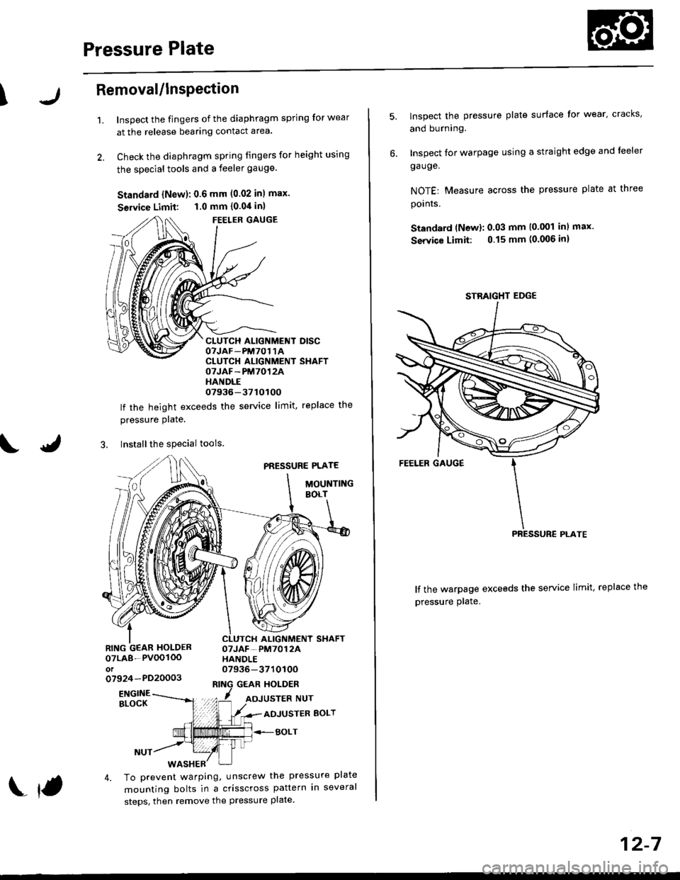
1.Inspect the fingers of the diaphragm spring for wear
at the release bearing contact area.
Check the diaphragm spring fingers for height using
the special tools and a feeler gauge.
Standard {New}: 0.6 mm (0.02 inl max.
Seruice Limit: 1.0 mm {0.04 in}
FEELER GAUGE
CLUTCH ALIGNMENT DISCOTJAF_PM7O1 1ACLUTCH ALIGNMENT SHAFTOTJAF-PM7012AHANDLE07936-37tOtOO
lf the height exceeds the service limit, replace the
pressure Plate.
3. Installthe special tools
PRESSURE PLATE
MOUNTINGBOLT
ALIGNMENT SHAFTOTJAF-PM7012AHANDLE07936-371010Oo7924-PD20003GEAR HOLDER
07LA8-PVOOIOOot
ENGINEBLOCKADJUSTER BOLT
BOLT
4. To prevent warping, unscrew the pressure plate
mounting bolts in a crisscross pattern in several
steps, then remove the pressure plate.
f
12-7
lnspect the pressure plate surface for wear' cracks,
and burning.
Inspect for warpage using a straight edge and leeler
ga uge.
NOTEr Measure across the pressure plate at three
pornrs.
Standard (Newl: 0.03 mm (0.001 inl max.
Service Limit: 0.15 mm (0.006 inl
lf the warpage exceeds the service limit, replace the
pressure plate.
STBAIGHT EDGE