Page 575 of 2189
Clutch Disc
RemovaUlnspection
2.
'1. Remove the clutch disc and special tools.
CLUTCH
CLUTCH ALIGNMENT SHAFToTJAF-pM7012A xltori07936-3710100
Inspect lining of the clutch disc for signs of slipping
or oil. lf it is burned black or oil soaked, replace it.
Measure the clutch disc thickness.
Clulch Disc Thickness:
Standard (Now): 8.5 - 9.1 mm (0.33 - 0.36 in)
Servic€ Limit: 5.5 mm (0.22 inl
CLUTCH
lf the thickness is less than the service limit. .eolacethe clutch disc.
12-8
U
4. Measure the depth from the lining surface to therivets, on both sides.
Rivet Depth:
Standard lNewl: 1.3 - 1.9 mm {0.05 - 0.07 in} min.
Service Limit: 0.2 mm (0.01 in)
lf the depth is less than the service limit, replace the
clutch disc.
CLUTCH DISC
Page 577 of 2189
FlywheelClutch Disc, Pressure Plate
Replacement (cont'dl
4. Drive the new ball bearing into the flywheel using
the special tools as shown.
DRIVER07749-0010000
ATTACHMENT,32x35mm07746-OOIOTOO
FLYWHEEL
BEARING
Align the hole in the flywheel with the crankshaft
dowel pin and install the flywheel. Install the
mounting bolts finger-ti9ht.
Install special tool, then torque the flywheel mount-
ing bolts in a crisscross pattern in several steps as
snown.
5.
6.
MOUNTING BOLTS118 N.m (12.0 kgl.m,87 tbf.ft)
RING GEAR HOLDER07LAB-PV00100ol07924 -PO20003
WVa// ,
12-10
Installation
1. Install the special tool.
Y
07936-3710r00
{P/N 08798-90021
RING GEAR HOLDER07LAB-PVOO100ot07924-PD20003
CLUTCH ALIGNMENT SHAFTOTJAF_PM7012A
2.
3.
Installthe clutch disc using the special tools.
Install the pressure plate.
RING GEAR HOLDERoTLAB PV00'l OO
07924 PD20003
OTJAF_PM70124HANOLE07936-3710100
CLUTCH DISC
Page 578 of 2189
Release Bearing
)
4. Torque the mounting bolts in a crisscross pattern as
shown. Tighten them in several steps to prevent
warping the diaPhragm sPring.
19 rbf.ft)
\
RING GEAR HOLDERoTLAB-PV00100ot07924-PD20003
CLUTCH ALIGNMENT SHAFT
OTJAF_PM7O12AHANOLE07936-3710100
MOUNTING BOLTS
8 x 1.25 mm
25 N.m (2.6 kgl'm.
Removal/lnspection
1. Remove the release fork boot from the clutch hous-
Ing.
2. Remove the release fork from the clutch housing by
squeezing the release fork set spring with pliers
Remove the release bearing.
Check the release bearing for play by spinning it by
hand.
CAUTION: The releass bearing is packed with
grease. Do not wash it in solvent.
lf there is excessive play, replace the release bear-
ing with a new one.
RELEASE FORK
12-11
Page 589 of 2189

. Torque the mounting bolt and nuts in the sequence
shown.
O 12 x 1.25 mm64 N.m {6.5 kgt.m,47 lbf.fr)
@ 12 x 1.25 mm74 N.m (7.5 kgl'm,54 tbt.fr)
Check that the bushings are not twisted or offset.
Install the clip as shown.
SHIFT ROD
Turn the boot so the hole is facing down.
Make sure the boot is installed on the shift rod.
O) 12 x 'l.25 mm64 N.m 16.5 kgl.m,47 tbt.ft)
I
a
a
a
a
8 x 1.25 mmN.m t2.2 kgt.m, l6 lbl'tt)
6 x 1.0 mm9.8 N.m (1.0 kgl.m.7.2 tbf.tr)
. Apply grease to the slave cylinder push rod.
NOTE: Use only Super High Temp Urea Grease
{P/N 08798 - 9002}.
CLUTCHUNE
a
a
(P/N-6tl
08798-9002)
8 x 1.25 mm22 N.m 12.2 kgl.n.16 tbf.frl
. Turn the breather cap so that the "F" mark points at
the front of the car as shown.
Refill the transmission with the recommended oil
(see page 13-3).
Connect the positive (+) cable first, then the negative
(-) cable to the battery.
Check the clutch oDeration,
Shift the transmission and check for smooth opera-
tion.
Check the front wheel alignment (see section 18).
FRONT
13-9
Page 633 of 2189
. Apply grease to the slave cylinder push rod.
NOTE: Use only Super High Temp Urea Grease
(P/N 08798 - 9002).
6x1.0mm9.8 N'm (1.0 kgl m,
7.2 tbl.ft)
-6,4- 9m2)
Refillthe transmission with oil (see page 13-47).
Connect the positive (+) cable first, then the negative
( - ) cable to the battery.
Check the clutch oPeration.
Shift the transmission, and check for smooth opera-
tion.
Check the front wheel alignment (see section 181.
(P/N 08798
8 x 1 .25 mm22N.n 12.2 kgl'm,16 tbf.ftl
a
a
a
a
Page 790 of 2189

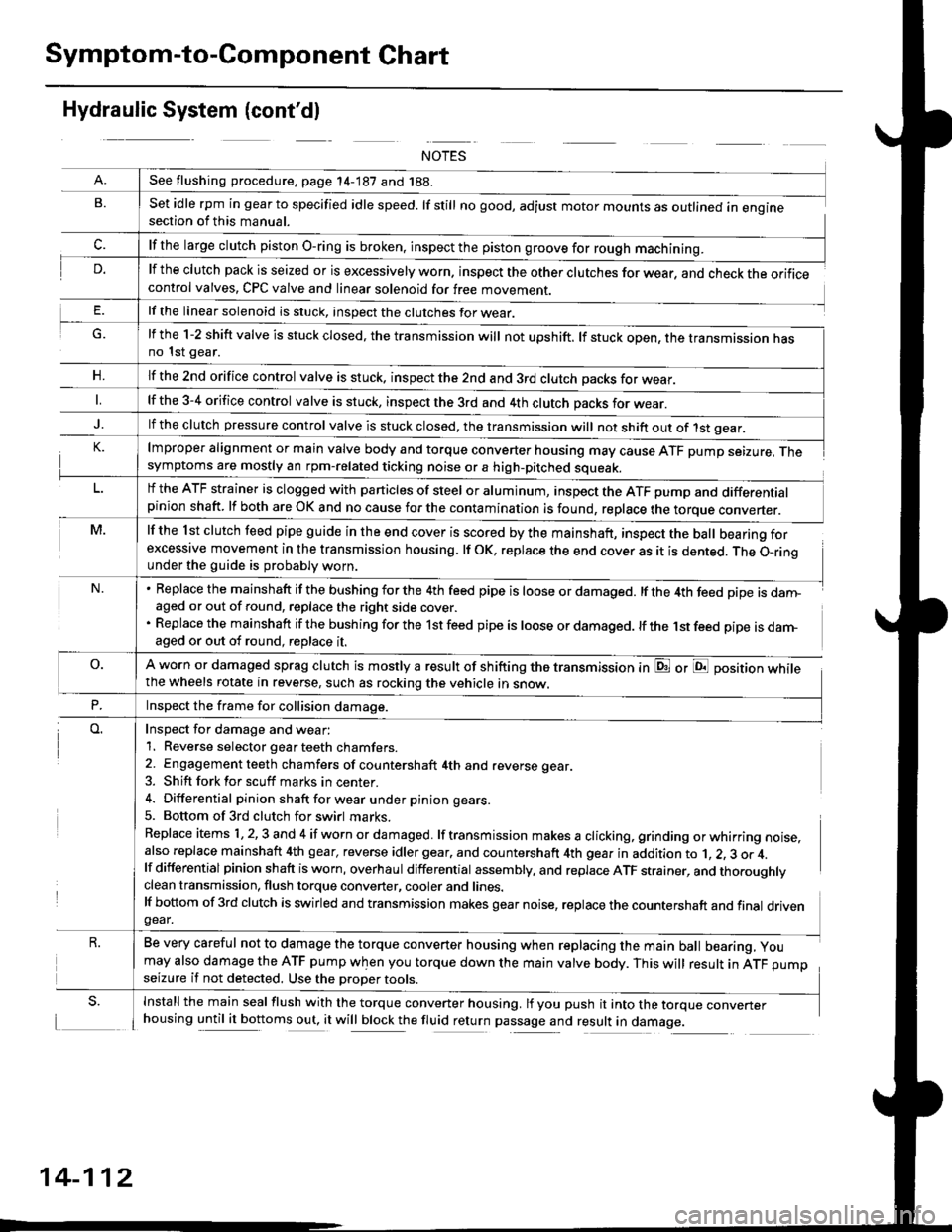
Symptom-to-Component Chart
Hydraulic System (cont'dl
G.
n,
set idle rpm in gear to specified idle speed. lf still no good, adjust motor mounts as outlined in enginesection of this manual.
lf the clutch pack is seized or is excessively worn. inspect the other clutches for wear, and check the orificecontrol valves, CPC valve and linear solenoid for free movement.
lf the linear solenoid is stuck, inspect the clutches for wear.
lmproper alignment or main valve body and torque converter housing may cause ATF pump seizure. Thesymptoms are mostly an rpm-related ticking noise or a high-pitched squeak.
lf the l st clutch feed pipe guide in the end cover is scored by the mainshaft, inspect the ball bearing forexcessive movement in the transmission housing. lf oK, replace the end cover as it is dented. The o-rinounder the guide is probably worn.
Replace the mainshaft if the bushing for the 4th feed pipe is loose or damaged. lf the 4th feed pipe is danFaged or out of round, replace the right side cover.
Replace the mainshaft if the bushing for the 1st feed pipe is loose or damaged. lf the 1st feed pipe is darn-aged or out of round, replace it.
A worn or damaged sprag clutch is mostly a result of shifting the transmission inthe wheels rotate in reverse, such as rocking the vehicle in snow.
or E position while
Inspect for damage and wear:
1. Reverse selector gear teeth chamfers.
2. Engagement teeth chamfers of countershaft 4th and reverse gear.
3. Shift fork for scuff marks in center.
4. Differential pinion shaft for wear u nder pin ion gears.
5. Bottom of 3rd clutch for swirl marks.
Replace items 1,2,3 and 4 if worn or damaged. lf transmission makes a clicking, grinding orwhirring noise,also replace mainshaft 4th gear, reverse idler gear. and countershaft 4th gear in addition to 1, 2, 3 or 4.lf differential pinion shaft is worn, overhaul differential assembly, and replace ATF strainer, and thoroughlyclean transmission, flush torque converter, cooler and lines.lf bottom of 3rd clutch is swirled and transmission makes gear noise, replace the countershaft and final drivengear.
Be very careful not to damage the torque converter housing when replacing the main ball bearing, you
may also damage the ATF pump when you torque down the main valve body. This will result in ATF pumpseizure if not detected. Use the oroper roors.
Install the main seal flush with the torque converter housing. lf you push it into the torque converterhousing until it bottoms out, it will block the fluid return passage and result in damage.
See flushing procedure, page 14-187 and 188.
lf the large clutch piston O-ring is broken, inspect the piston groove for rough machining.
lf the l-2 shift valve is stuck closed, the transmission will not upshift. lf stuck open, the transmission hasno 1st gear.
lf the znd orifice control valve is stuck. inspect the 2nd and 3rd clutch oacks for wear.
lf the 3-4 orifice control valve is stuck, inspect the 3rd and 4th clutch oacks for wear.
lf the clutch pressure control valve is stuck closed, the transmission will not shift out of 1st gear.
lf the ATF strainer is clogged with particles of steel or aluminum, inspect the ATF pump and differentialpinion shaft. lf both are OK and no cause for the contamination is found, replace the torque converter.
Inspect the frame for collision damage.
14-112
Page 864 of 2189

Transmission
Installation {cont'd)
Connect the lock-up control solenoid connector. andinstall the transmission ground cable.
6 x '1.0 mm12 N.m {1.2 kgf.m, 8.7 lbl.ft}
LOCK.UP CONTROLSOLENOID CONNECTOR
Connect the staner cables on the staner motor. andinstall the cable holder.
NOTE; When installing the starter cable terminal.make sure that the crimped side of the ring terminalis facing out (see section 23).
6x1.0mm12 N.m 11.2 kg{.m.8.7 tbtftl
{0.9 kg'f.m, 7 lbf.ftl
TRANSMISSIONGROUND CABLE
b
14-186
STARTER CAELE
24. Installthe intake air duct.
D16Y7 engine:
Install the intake air duct and the resonaror.
D16Y8 engine:
lnstall the intake air duct and the air cleaner hous_ang assembly.
25. Refill the transmission with ATF (see page 14_1.18).
26. Connect the positive (+) cable first. then the nega-tive (-) cable to the battery.
27. Check the ignition timing (see section 23).
28. Start the engine. Set the parking brake, and shift thetransmission through all gears. three times. Checkthe shift cable adjustment (see page 14_190).
29, Check the front wheel alignment (see section 1g).
30. Let the engine reach operating temperature (thecooling fan comes on) with the transmission in Nor @ position, then turn it off and check the fluidlevel (see page 14- 7).
31. Road test as described on pages 14-113 thru ,14_116.
Page 868 of 2189

Shift Cable
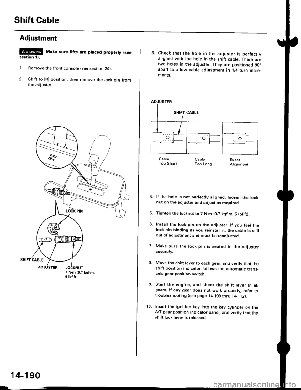
Adjustment
@ Make sure lifts are ptaced properly (see
section 1).
1. Remove the front console (see section Z0l.
2. Shift to @ position. then remove the lock pin fromthe adiuster.
7 N.m (0.75 tbtftlkgtm.
14-190
3. Check that the hole in the adjuster is perfectlyaligned with the hole in the shift cable. There aretwo holes in the adjuster. They are positioned 90.apart to allow cable adjustment in 1/4 turn incre-ments.
ExactAlignment
4. lf the hole is not perfectly aligned, loosen the lock-nut on the adjuster and adjust as required.
5. Tighten the tocknut to 7 N.m (0.7 kgf.m, 5 tbf.ft).
6. Install the lock pin on the adjuster. lf you feel thelock pin binding as you reinstall it, the cable is stillout of adjustment and must be readjusted.
7. Make sure the lock pin is seated in the adjustersecuretv.
8. Move the shift lever to each gear, and verify that theshift position indicator follows the automatic trans-axle gear position switch.
9. Start the engine, and check the shift lever in allgears. lf any gear does not work properly, refer totroubleshooting (see page 14-109 thru 1'4-'112).
10. Insert the ignition key into the key cylinder on theAy'T gear position indicator panel, and verify that theshift lock lever is released.
CableToo ShortCableToo Long