Page 1032 of 2189
Shift Lever
KNOBLEVER
SCREW
,l
PUSH KNOE SPRING
SHIFTPUSH KNOB
\
e
X./
,/
-6rSILICONE GREASE
SHIFT INDICATOR LAMP.
SCREW3 N.m 10.3 kgl.m.2 lbf.ttl
/ tnrnJl / I 3 N.n l0.3 xgt m, 2 lbf ftl
a,-,/ / Apply non-hardening th'
\2 I
Apply non-hardening thread lock sealant.
SCREW3 N.m {0.3 kgf'm, 2 lbl.ft)
A/T GEAR POSTTON INDICATOR PANEL
LEVER COVER
A/T GEAR POSMON SWNCH
BUSHING
-611SII.'|CONE GREASE
SHIFT I.TVEB ASSEMBLY
dE("""-- L@KP'N
n2
SHIFT LOCKsotENolD
6x1.0mm9,8 N.m 11.0 kgf.m,7.2 tbtft)-
A/T GEAR POSITIONPLAYE
3 N.m 10,3 kqf.m,2tbfitl
SHIFT LEVEN BRACKET BASE
SHIFT LEVER
6x1.0mm9.8 N.m {1.0 kgf.m,7.2 lbf ftl
BASE COLLAR
14-356
Page 1062 of 2189
Steering Gearbox
Removal(cont'd)
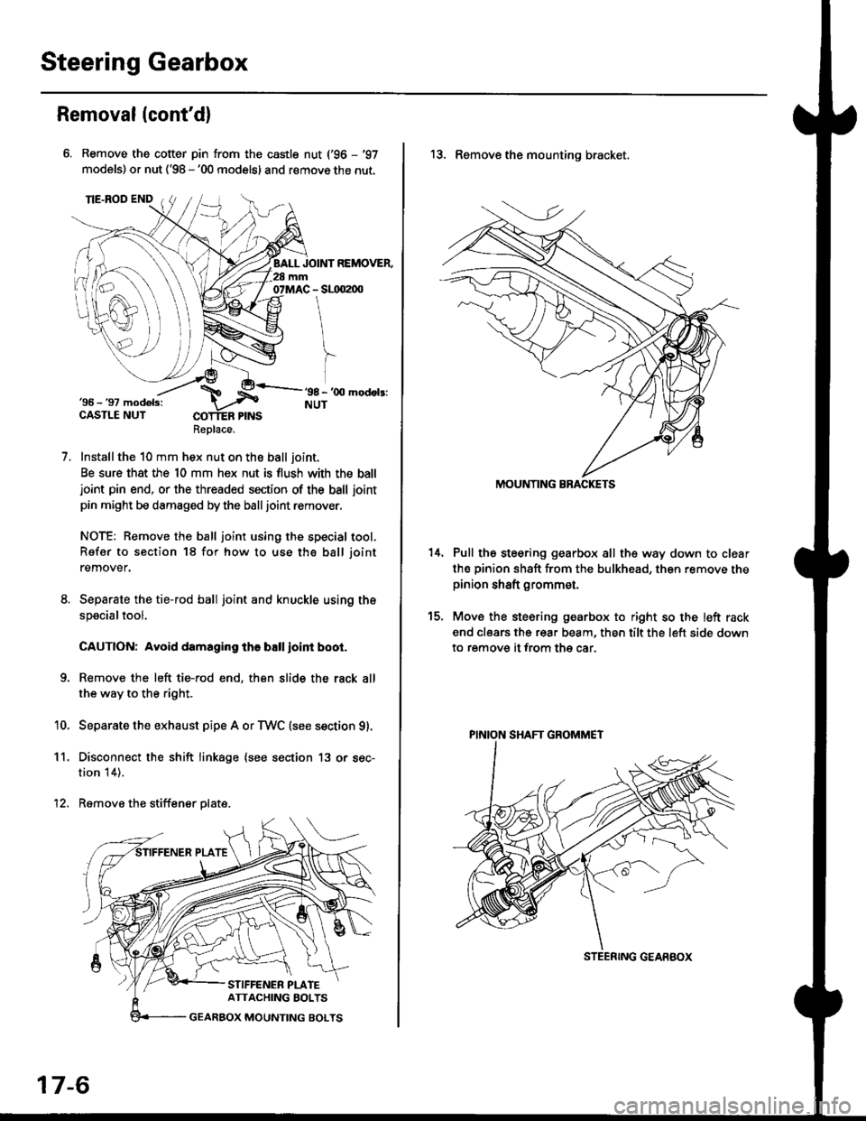
Remove the cotter pin from the castle nut ('96 - '97
models) or nut ('98 - '00 models) and remove the nut.
Installthe 10 mm hex nut on the ball joint.
Be sure that the 10 mm hex nut is flush with the balljoint pin end, or the threaded section of the ball joint
pin might be damaged by the balljoint remover.
NOTE: Remove the ball joint using the special tool,
Refer to section 18 for how to use tho ball joint
remover.
Separate the tie-rod ball joint and knuckle using the
specialtool.
CAUTION: Avoid damaging the ball ioint boot.
Remove the left tie-rod end, then slide the rack all
the way to the right.
Separate the exhaust pipe A or TWC (see section g).
Disconnect the shift linkage (see section 13 or sec-
tion 14).
Remove the stiffener plate.
7.
'10.
11.
12.
Replace.
17-6
13. Remove the mounting bracket,
Pull the steering gearbox all the way down to clear
th€ pinion shaft from the bulkhead, then remove thepinion shaft grommet,
Move the steering gearbox to right so the left rack
end clears the rear beam, then tilt the left side down
to remove it from the car.
t5.
STEENING GEARBOX
PINION SHAFT GROMMET
Page 1063 of 2189
)
Disassembly
'1.
2.
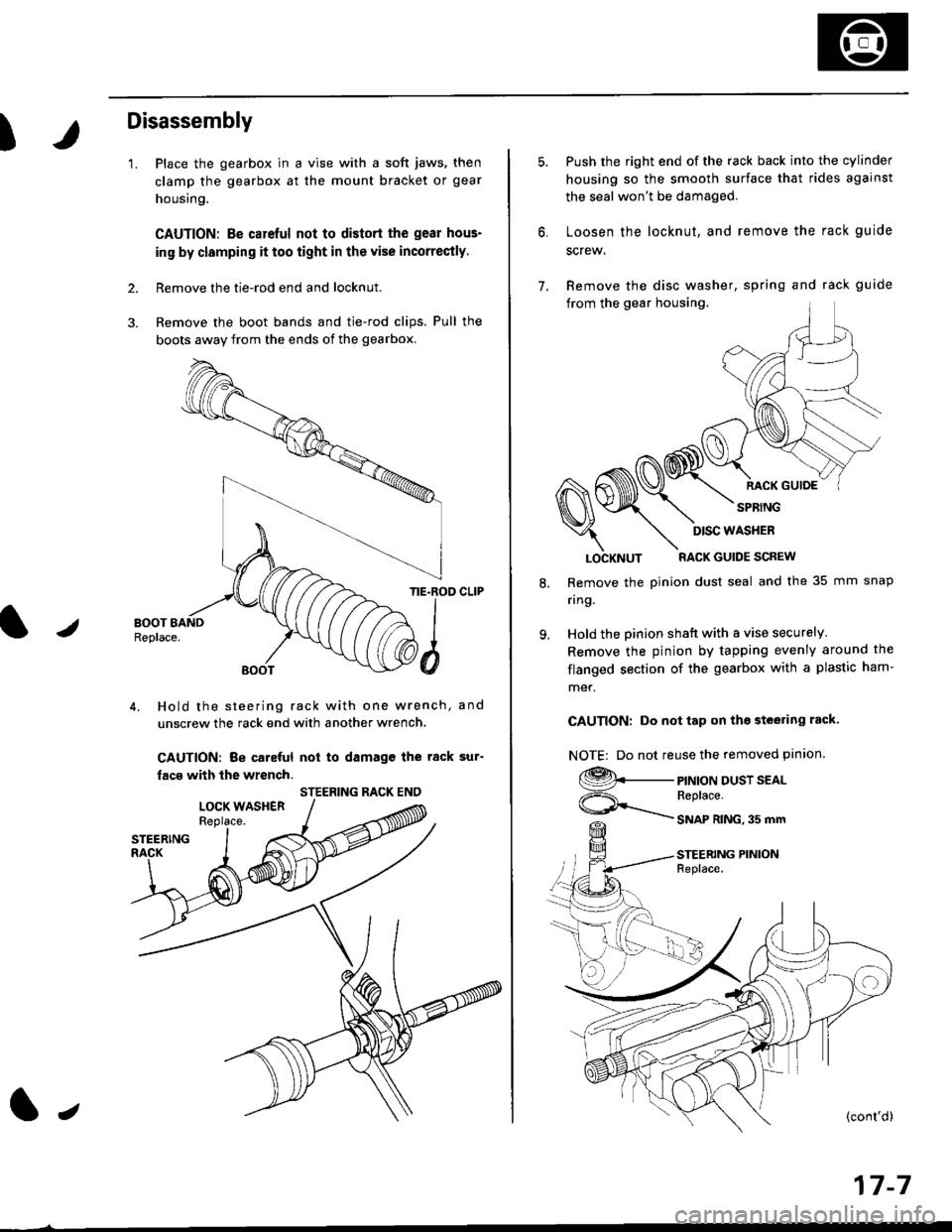
Place the gearbox in a vise with a soft jaws, then
clamp the gearbox at the mount bracket or gear
housing.
CAUTION: Be carcful not to distort the gear hous-
in9 by clamping it too iight in the vise incorrectly.
Remove the tie-rod end and locknut.
Remove the boot bands and tie-rod clips. Pull the
bogts away from the ends of the gearbox.
/
TIE.ROD CLIP
4. Hold the steering rack with one wrench, and
unscrew the rack end with another wrench.
CAUTION: Be caleful not to damagc the rack sur'
facs with the wrench.
STEERING RACK ENO
l,
17-7
7.
Push the right end of the rack back into the cylinder
housing so the smooth surface that rides against
the seal won't be damaged.
Loosen the locknut, and remove the rack guide
screw.
Remove the disc washer, spring and rack guide
from the gear housing.
RACK GUIOE
SPRING
8.
9.
LOCKNUT RACK GUIDE SCREW
Remove the pinion dust seal and the 35 mm snap
nng.
Hold the pinion shatt with a vise securely
Remove the pinion by tapping evenly around the
flanged section of the gearbox with a plastic ham-
met.
CAUTION: Do not tap on tho steering rack.
NOTE| Do not reuse the removed pinion.
9._
ViF=\_
PINION DUST SEALReplace.
SNAP RING,35 mm
STEERING PINIONFeplace.
DISC WASHER
Page 1069 of 2189
)
lnstallation
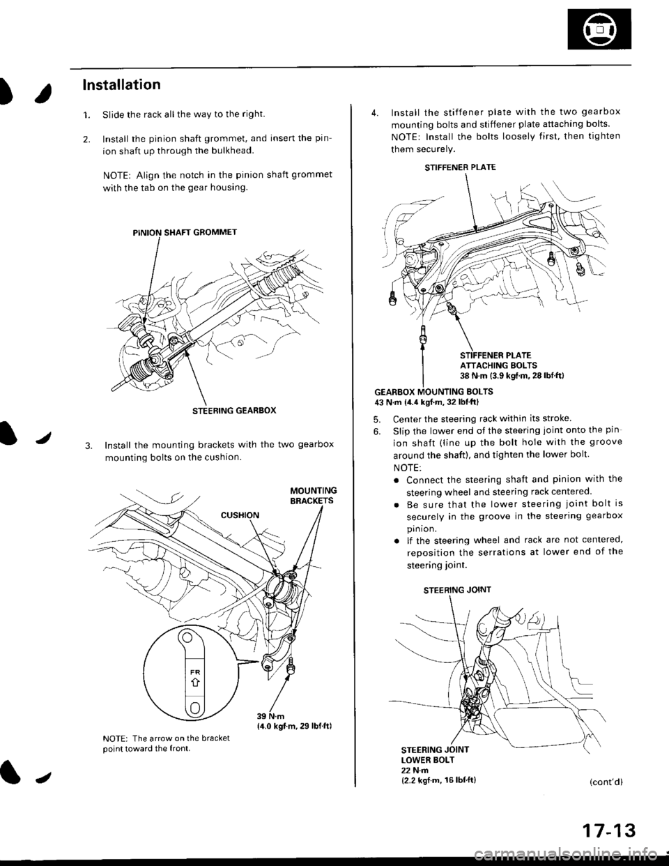
Slide the rack all the way to the righl
Install the pinion shaft grommet, and insert the pin
ion shaft up through the bulkhead.
NOTE| Align the notch in the pinion shaft grommet
with the tab on the gear housing.
1.
2.
J3. Install the mounting brackets with the two gearbox
mounting bolts on the cushion.
NOTE: The arrow on the bracketpoint toward the front.
STEEBING GEARBOX
{4.0 kgt.m,29 lbf.ftl
J
4. Install the stiffener plate with the two gearbox
mounting bolts and stiffener plate attaching bolts.
NOTEr Install the bolts loosely first. then tighten
them securely.
GEARBOX MOUNTING EOLTS43 N.m {4.4 kgf.m, 32 lbf'ftl
5. Center the steering rack within its stroke
6. Slip the lower end ot the steering joint onto the pin
ion shaft (line up the bolt hole with the groove
around the shaft), and tighten the lower bolt.
NOTE:
. Connect the steering shaft and pinion with the
steering wheel and steering rack centered
Be sure that the lower steering joint bolt is
securely in the groove in the steering gearbox
pin ion.
lf the steering wheel and rack are not centered,
reposition the serrations at lower end of the
steering ioint.
STEERING JOINT
STEERING JOINTLOWER BOLT22 N.m{2.2 kgf.m, 16lbf'ft}(cont'd)
I t- t5
STIFFENER PLATE
ATTACHING BOLTS38 N.m (3.9 kgf.m.28lbf.ftl
Page 1094 of 2189
Steering Column
Inspection
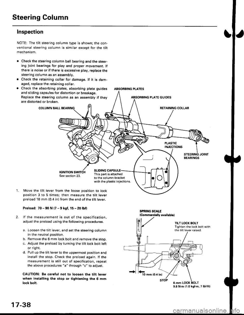
NOTE: The tilt steering column type is shown; the con-
ventional steering column is similar except for the tilt
mechantsm.
Check the steering column ball bearing and the steer-ing joint bearings for play and proper movement. lf
there is noise or if there is excessive play, replace the
steering column as an assembly.
Check the retaining collar for damage. lf it is dam-
aged, replace the retaining collar.
Check the absorbing plates, absorbing plate
and sliding capsules for distonion or breakage.
Replace the steering column as an assembly
are distorted or broken.
COLUMN BALL
ABSORBING PLATE GUIDES
guides
if they
SLIDING
BEARINGS
TILT LOCK BOLTTighten the lock bolt withthe tilt lever raised.
This part is attachodto the column bracketwith the plastic injections.
1.Move the tilt lever from the loose position to lockposition 3 to 5 times; then measure the tilt leverpreload l0 mm {0.4 in) from the end ofthe tilt lever.
Preload: 70 - 90 N (7 - 9 kgf. 15 - 20 lbf)
lf the measurement is out of the specification,
adjust the pfeload using the following procedures.
a. Loosen the tilt lever, and set the steering column
in the neutral position.
b. Remove the 6 mm lock bolt and remove the stop.
c. Adjust the preload by turning the tilt lock bolt left
or flgnr.
d. Pull up the tilt lever to the uppermost position and
install the stop. Check the preload again. lf the
measurement is still out of specification, repeat
the above procedures "a" through "c" to adjust.
CAUTION: Be caretul not to loosen tho tilt lever
when installing the stop or tightening the 6 mm
lock bolt.
17 3a
10 mm (0.4 inl
9.8 N.m (1.0 kgl.m,7 lbf.ft)
Page 1096 of 2189
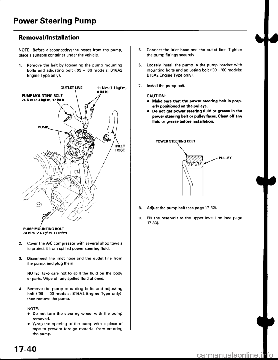
Power Steering Pump
RemovaUlnstallation
NOTE: Eefore disconnecting the hoses from the pump,
Dlace a suitable container under the vehicle.
1. Remove the belt by loosening the pump mounting
bolts and adjusting bolt ('99 -'00 models: 81642
Engine Type only).
OUTLET LINE11 N.m {1.1 kgf'm,8
L
PUMP MOUNTING BOLT24 N.m (2.4 kgl.m, 17 lbf ft)
2. Cover the Ay'C compressor with several shop towels
to protect it from spilled power steering fluid.
3. Disconnect the inlet hose and the outlet line from
the pump, and plug them.
NOTE: Take care not to spill the fluid on the body
or parts, Wipe off any spilled fluid at once.
4. Remove the pump mounting bolts and adjusting
bolt ('99 -'00 models: 816A2 Engine Type only),
then remove the pump.
NOTE:
. Do not turn the steering wheel with the pump
removeo.
. Wrap the opening of the pump with a piece of
tape to prevent foreign material from entering
the pump.
17-40
1.
8.
Connect the inlet hose and the outlet line. Tiqhten
the pump fittings securely.
Loosely install the pump in the pump bracket with
mounting bolts and adjusting bolt ('99 -'00 models:
81642 Engine Type only).
Installthe pump belt.
CAUTION:
. Make sure that the power steering belt is prop-
orly positioned on the pulleys.
. Do not get power stoering tluid or grease in the
power steering bsh or pulley faces. Clean off any
fluid or grease before installrtion.
Adjust the pump belt (see page 17-32).
Fill the reservoir to the upper level line (see page
Page 1104 of 2189
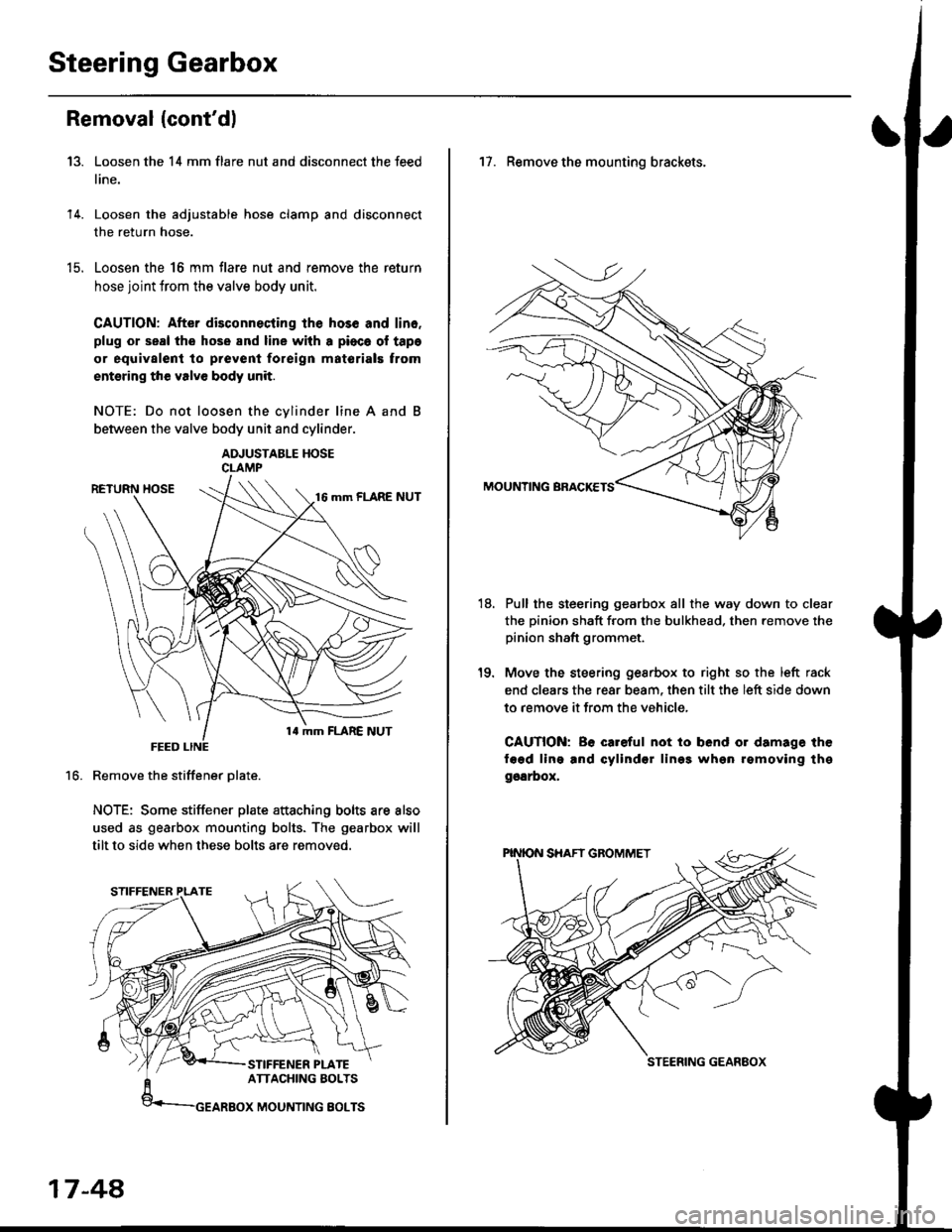
Steering Gearbox
Removal {cont'dl
Loosen the 14 mm flare nut and disconnect the feed
line.
Loosen the adjustable hose clamp and disconnect
the return hose.
Loosen the 16 mm flare nut and remove the return
hose joint trom the valve body unit.
CAUTION: After disconnecting lhe hos6 and lin6.
plug or seal the hose and line with a pioca ol tapa
or equivalent to prevenl foreign matorials trom
entsring the valve body unit.
NOTE: Do not loosen the cvlinder line A and
between the valve body unit and cylinder.
ADJUSTABLE HOSECLAMP
Remove the stiffener Dlate.
NOTE: Some stiffener plate attaching bolts are also
used as gearbox mounting bolts. The gearbox will
tilt to side when these bolts are removed.
13.
14.
t9.
16.
17-48,
17. Remove the mounting brackets.
Pull the steering gearbox all the way down to clear
the pinion shaft from the bulkhead. then remove the
pinion shaft grommet.
Move the steering gesrbox to right so the left rack
end clears the rear beam, then tilt the left side down
to remove it from the vehicle,
CAUTION: Be careful not io bend or damage the
fagd ling and cylindsr lin99 whgn rgmoving thg
ggarbox,
18.
STEERING GEANEOX
Page 1121 of 2189
71.Connect the air tube between the right and left
boot.
lnstall the clips on the cylinder lines' then clamp the
air tube with the cliPs.
l./
CYLINDER LINE A
CLIP
l-,
lnstallation
CAUTION: Be carelul not to bend or damage the feed
line and cylinder lines when installing the gearbox'
1, Before installing the gearbox, slide the rack all the
way to right.
2. Install the mounting cushion on the steering gear-
DOX.
Install the pinion shaft grommet, then insert the pin-
ion shaft up through the bulkhead.
NOTE: Align the notch in the pinion shaft grommet
with the tab on the valve housing.
Install the mounting bracket over the mounttng
cushion, then installtwo gearbox mounting bolts'
MOUNTING BRACKET
cusHroN
39 N.m(4.0 kgj m, 29 lbtftlNOTE: Install the bracket
with the arrow Pornllngtoward the front.(cont'd)
17-65