1999 DODGE RAM lock
[x] Cancel search: lockPage 183 of 1691

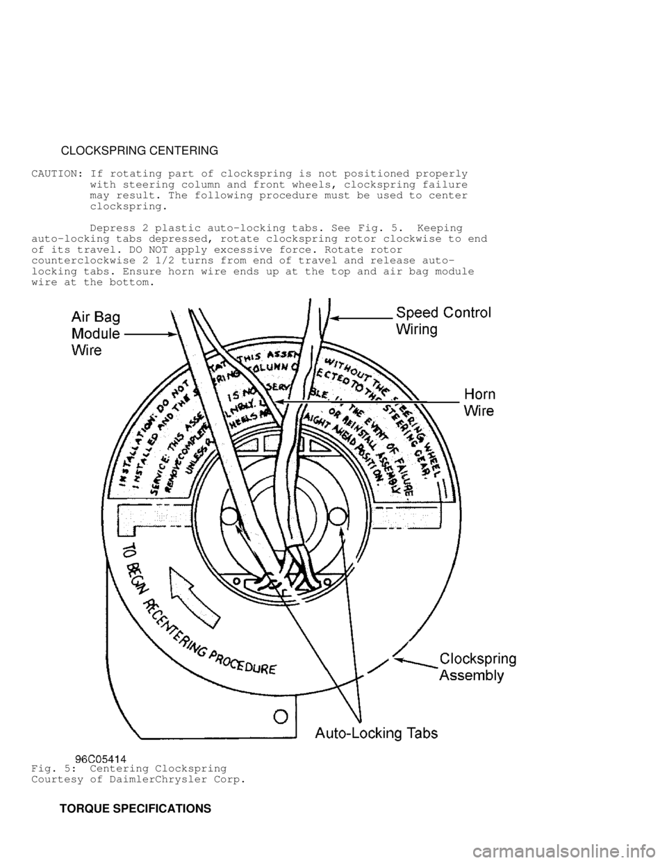
CLOCKSPRING CENTERING
CAUTION: If rotating part of clockspring is not positioned properly
with steering column and front wheels, clockspring failure
may result. The following procedure must be used to center
clockspring.
Depress 2 plastic auto-locking tabs. See Fig. 5. Keeping
auto-locking tabs depressed, rotate clockspring rotor clockwise to end
of its travel. DO NOT apply excessive force. Rotate rotor
counterclockwise 2 1/2 turns from end of travel and release auto-
locking tabs. Ensure horn wire ends up at the top and air bag module
wire at the bottom.
Fig. 5: Centering Clockspring
Courtesy of DaimlerChrysler Corp.
TORQUE SPECIFICATIONS
Page 190 of 1691

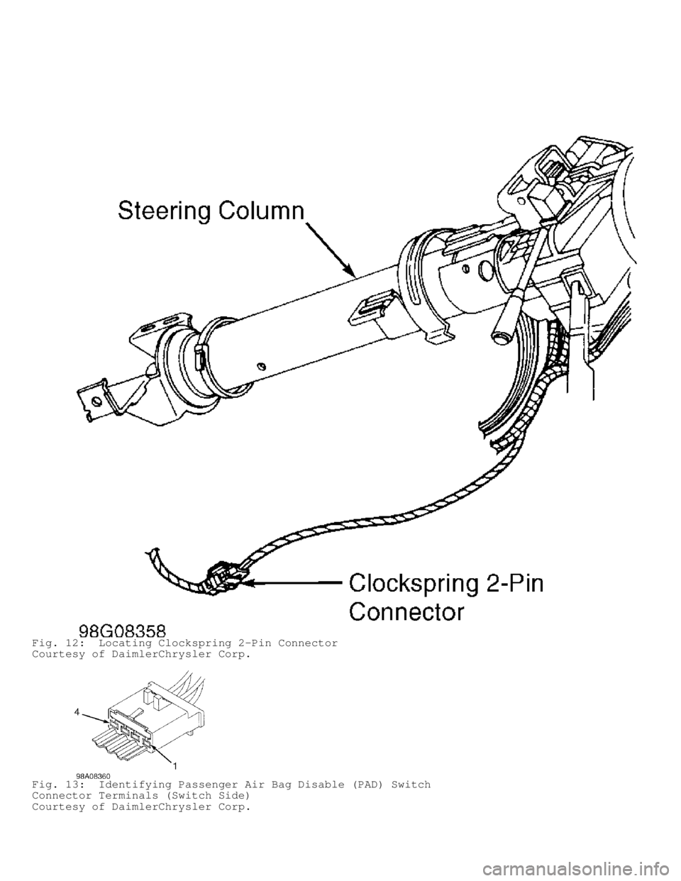
Fig. 12: Locating Clockspring 2-Pin Connector
Courtesy of DaimlerChrysler Corp.
Fig. 13: Identifying Passenger Air Bag Disable (PAD) Switch
Connector Terminals (Switch Side)
Courtesy of DaimlerChrysler Corp.
Page 193 of 1691

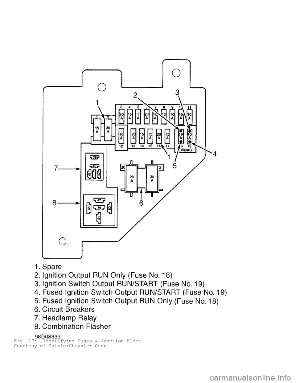
Fig. 17: Identifying Fuses & Junction Block
Courtesy of DaimlerChrysler Corp.
Page 194 of 1691

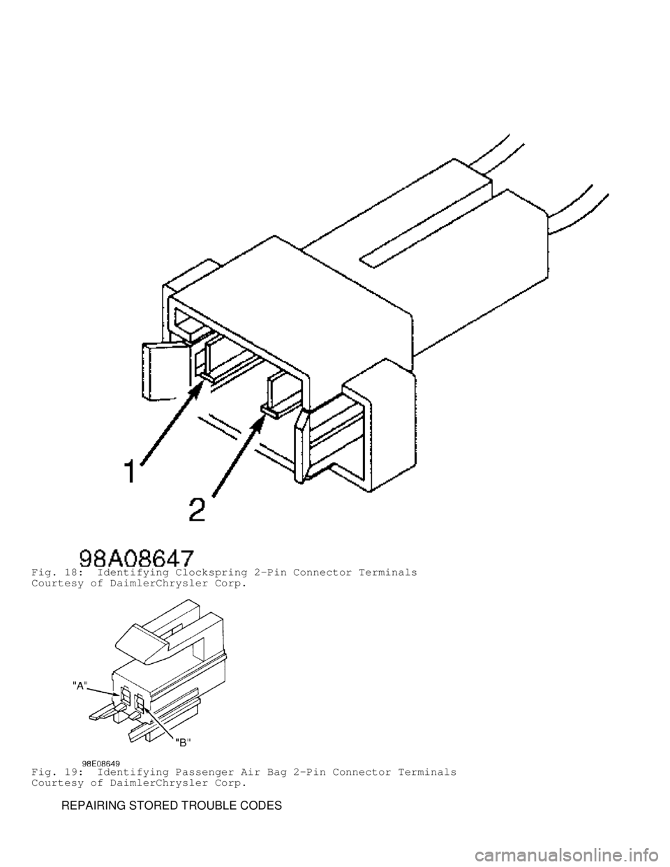
Fig. 18: Identifying Clockspring 2-Pin Connector Terminals
Courtesy of DaimlerChrysler Corp.
Fig. 19: Identifying Passenger Air Bag 2-Pin Connector Terminals
Courtesy of DaimlerChrysler Corp.
REPAIRING STORED TROUBLE CODES
Page 196 of 1691

it to ensure it is in good condition. Always focus on circuit
being tested. Dirt, water and corrosion, are most common
problems in connectors. Due to manufacturer changes in wire
colors, use terminal identification whenever possible.
1) Disconnect battery and wait 2 minutes before proceeding.
Disconnect driver-side air bag module squib connector. Connect a
jumper wire between driver-side air bag (squib) 2-pin connector
terminal No. 1 (Black/Light Blue wire) and terminal No. 2 (Dark
Green/Light Blue wire). Turn ignition on (engine off). Reconnect
battery. Using DRB, read active codes. If DRB displays DRIVER SQUIB
CIRCUIT SHORTED, replace driver-side air bag module. If not, go to
next step.
2) Disconnect clockspring 2-pin connector. Connect a jumper
wire between clockspring 2-pin connector terminals No. 1 (Black/Light
Blue wire) and No. 2 (Dark Green/Light Blue wire). Using DRB, read
active codes. If DRB displays DRIVER SQUIB CIRCUIT SHORTED, replace
clockspring. If not, go to next step.
3) Disconnect battery and wait 2 minutes before proceeding.
Remove jumper wires. Disconnect ACM connector. ACM is located under
instrument panel, on transmission tunnel. Using an ohmmeter, check
resistance between ACM connector terminal No. 6 (Dark Green/Light Blue
wire) and clockspring 2-pin connector terminal No. 2 (Dark Green/Light\
Blue wire). If resistance is less than 5 ohms, go to next step. If
resistance is more than 5 ohms, repair open or high resistance in Dark
Green/Light Blue wire.
4) Check resistance between ACM connector terminal No. 5
(Black/Light Blue wire) and clockspring 2-pin connector terminal No. 1\
(Black/Light Blue wire). If resistance is less than 5 ohms, go to next\
step. If resistance is more than 5 ohms, repair open or high
resistance in Black/Light Blue wire.
5) If there are no potential causes for this DTC remaining,
ACM is assumed to be defective. Replace ACM. See
AIR BAG CONTROL MODULE (ACM) under REMOVAL & INSTALLATION.
DRIVER SQUIB CIRCUIT SHORTED
NOTE: Perform AIR BAG VERIFICATION TEST after
all repairs. Each time a connector is disconnected, inspect
it to ensure it is in good condition. Always focus on circuit
being tested. Dirt, water and corrosion, are most common
problems in connectors. Due to manufacturer changes in wire
colors, use terminal identification whenever possible.
1) Disconnect battery and wait 2 minutes before proceeding.
Ensure driver-side air bag module connector is completely connected
before disconnecting it. If driver-side air bag module connector is
not completely connected, reconnect it. If driver-side air bag
connector is completely connected, go to next step.
2) Disconnect driver-side air bag module. Turn ignition on
(engine off). Reconnect battery. Using DRB, read active codes. If DRB
displays DRIVER SQUIB CIRCUIT OPEN, replace driver-side air bag
module. If not, go to next step.
3) Disconnect clockspring 2-pin connector. Using DRB, read
active codes. If DRB displays DRIVER SQUIB CIRCUIT OPEN, replace
clockspring. If not, go to next step.
4) Turn ignition off, disconnect battery and wait 2 minutes
before proceeding. Disconnect passenger-side air bag module connector.
Using an ohmmeter, check resistance between clockspring 2-pin
connector terminal No. 1 (Black/Light Blue wire) and passenger-side
air bag 2-pin connector terminal "A" (Black/Yellow wire). If
resistance is less than 5 ohms, repair short between Black/Light Blue
wire and Black/Yellow wire. If resistance is more than 5 ohms, go to
Page 197 of 1691

next step.
5) Using an ohmmeter, check resistance between clockspring 2-
pin connector terminals No. 1 (Black/Light Blue wire) and No. 2 (Dark\
Green/Light Blue wire). If resistance is less than 5 ohms, repair
short between Dark Green/Light Blue wire and Black/Light Blue wire. If
resistance is more than 5 ohms, go to next step.
6) If there are no potential causes for this DTC remaining,
ACM is assumed to be defective. Replace ACM. See
AIR BAG CONTROL MODULE (ACM) under REMOVAL & INSTALLATION.
DRIVER SQUIB CIRCUIT SHORTED TO BATTERY
NOTE: Perform AIR BAG VERIFICATION TEST after
all repairs. Each time a connector is disconnected, inspect
it to ensure it is in good condition. Always focus on circuit
being tested. Dirt, water and corrosion, are most common
problems in connectors. Due to manufacturer changes in wire
colors, use terminal identification whenever possible.
1) Disconnect battery and wait 2 minutes before proceeding.
Disconnect driver-side air bag module. Turn ignition on and reconnect
battery. Using DRB, read active codes. If DRB does not display DRIVER
SQUIB CIRCUIT SHORTED TO VOLTAGE, replace driver-side air bag module.
If DRB displays DRIVER SQUIB CIRCUIT SHORTED TO VOLTAGE, go to next
step.
2) Disconnect clockspring 2-pin connector. Using DRB, read
active codes. If DRB does not display DRIVER SQUIB CIRCUIT SHORTED TO
VOLTAGE, replace clockspring. If DRB displays DRIVER SQUIB CIRCUIT
SHORTED TO VOLTAGE, go to next step.
3) Disconnect battery and wait 2 minutes before proceeding.
Disconnect ACM 23-pin connector. Using a voltmeter, check voltage
between ground and clockspring connector terminals No. 1 (Black/Light
Blue wire) and No. 2 (Dark Green/Light Blue wire). If voltage is more\
than 5 volts on either circuit, repair short to voltage in Dark
Green/Light Blue wire or Black/Light Blue wire. If voltage is less
than 5 volts on either circuit, go to next step.
4) If there are no potential causes for this DTC remaining,
ACM is assumed to be defective. Replace ACM. See
AIR BAG CONTROL MODULE (ACM) under REMOVAL & INSTALLATION.
DRIVER SQUIB CIRCUIT SHORTED TO GROUND
NOTE: Perform AIR BAG VERIFICATION TEST after
all repairs. Each time a connector is disconnected, inspect
it to ensure it is in good condition. Always focus on circuit
being tested. Dirt, water and corrosion, are most common
problems in connectors. Due to manufacturer changes in wire
colors, use terminal identification whenever possible.
1) Disconnect battery and wait 2 minutes before proceeding.
Disconnect driver-side air bag module. Turn ignition on (engine off)
and reconnect battery. Using DRB, read active codes. If DRB does not
display DRIVER SQUIB CIRCUIT SHORTED TO GROUND, replace driver-side
air bag module. If DRB displays DRIVER SQUIB CIRCUIT SHORTED TO
GROUND, go to next step.
2) Disconnect clockspring 2-pin connector. Using DRB, read
active codes. If DRB does not display DRIVER SQUIB CIRCUIT SHORTED TO
GROUND, replace clockspring. If DRB displays DRIVER SQUIB CIRCUIT
SHORTED TO GROUND, go to next step.
3) Disconnect battery and wait 2 minutes before proceeding.
Disconnect ACM 23-pin connector. Using an ohmmeter, check resistance
between ground and clockspring connector terminals No. 1 (Black/Light
Blue wire) and No. 2 (Dark Green/Light Blue wire). If resistance is
Page 198 of 1691

more than 5 ohms on either circuit, repair short to ground in Dark
Green/Light Blue wire or Black/Light Blue wire. If resistance is less
than 5 ohms on either circuit, go to next step.
4) If there are no potential causes for this DTC remaining,
ACM is assumed to be defective. Replace ACM. See
AIR BAG CONTROL MODULE (ACM) under REMOVAL & INSTALLATION.
LOSS OF IGNITION RUN ONLY
NOTE: Perform AIR BAG VERIFICATION TEST after
all repairs. Each time a connector is disconnected, inspect
it to ensure it is in good condition. Always focus on circuit
being tested. Dirt, water and corrosion, are most common
problems in connectors. Due to manufacturer changes in wire
colors, use terminal identification whenever possible.
1) Remove and inspect fuse No. 18 located in junction block.
If fuse is blown, go to step 5). If fuse is good, go to next step.
2) Using a voltmeter, check voltage between ground and
ignition switch output RUN circuit at fuse No. 18. If voltage is less
than 10 volts, repair open ignition switch output RUN circuit. If
voltage is more than 10 volts, go to next step.
3) Reinstall fuse No. 18. Disconnect battery and wait 2
minutes before proceeding. Disconnect ACM connector. Turn ignition on,
then reconnect battery. Using a voltmeter, check voltage between
ground and ACM connector terminal No. 15 (Dark Blue/Yellow wire). If
voltage is more than 10 volts, go to next step. If voltage is less
than 10 volts, repair open in Dark Blue/Yellow wire.
4) If there are no potential causes for this DTC remaining,
ACM is assumed to be defective. Replace ACM. See
AIR BAG CONTROL MODULE (ACM) under REMOVAL & INSTALLATION.
5) Turn ignition off. Using an ohmmeter, check resistance
between ground and fused ignition switch output RUN circuit at fuse
No. 18. If resistance is more than 5 ohms, replace fuse No. 18 located
in junction block. If resistance is less than 5 ohms, go to next step.
6) Disconnect battery and wait 2 minutes before proceeding.
Disconnect ACM connector. Using an ohmmeter, check resistance between
ground and ACM connector terminal No. 15 (Dark Blue/Yellow wire). If
resistance is less than 5 ohms, repair fused ignition switch output
RUN circuit for a short to ground and replace fuse. If resistance is
more than 5 ohms, go to next step.
7) If there are no potential causes for this DTC remaining,
ACM is assumed to be defective. Replace ACM and fuse No. 18. See
AIR BAG CONTROL MODULE (ACM) under REMOVAL & INSTALLATION.
LOSS OF IGNITION RUN/START
NOTE: Perform AIR BAG VERIFICATION TEST after
all repairs. Each time a connector is disconnected, inspect
it to ensure it is in good condition. Always focus on circuit
being tested. Dirt, water and corrosion, are most common
problems in connectors. Due to manufacturer changes in wire
colors, use terminal identification whenever possible.
1) Remove and inspect fuse No. 19. If fuse is blown, go to
step 5). If fuse is good, go to next step.
2) Using a voltmeter, measure ignition switch output
RUN/START circuit between fuse No. 19 and ground. If voltage is less
than 10 volts, repair open ignition switch output RUN/START circuit.
If voltage is more than 10 volts, reinstall fuse No. 19. Disconnect
battery and wait 2 minutes before proceeding. Go to next step.
3) Disconnect ACM connector. Turn ignition on. Reconnect
battery. Using a voltmeter, check voltage between ground and ACM
Page 199 of 1691

connector terminal No. 14 (Light Green/Yellow wire). If voltage is
less than 10 volts, repair open in Light Green/Yellow wire. If voltage
is more than 10 volts, replace ACM.
4) If there are no potential causes for this DTC remaining,
ACM is assumed to be defective. Replace ACM. See
AIR BAG CONTROL MODULE (ACM) under REMOVAL & INSTALLATION.
5) Turn ignition off. Turn PAD switch to the ON position (if
equipped). Using an ohmmeter, check resistance at fused ignition
switch output RUN/START circuit between fuse No. 19 and ground. If
resistance is more than 5 ohms, replace fuse. If resistance is less
than 5 ohms, disconnect battery and wait 2 minutes before proceeding.
Disconnect ACM connector. Using an ohmmeter, check resistance between
ground and ACM connector terminal No. 14 (Light Green/Yellow wire). If\
resistance is less than 5 ohms, go to next step. If resistance is more
than 5 ohms, replace ACM and fuse No. 19.
6) Disconnect PAD switch. Using an ohmmeter, check resistance
between ground and ACM connector terminal No. 14 (Light Green/Yellow
wire). If resistance is less than 5 ohms, repair short to ground in
Light Green/Yellow wire and replace fuse No. 19. If resistance is more
than 5 ohms, replace fuse No. 19 located in junction block and go to
next step.
7) If there are no potential causes for this DTC remaining,
ACM is assumed to be defective. Replace ACM. See
AIR BAG CONTROL MODULE (ACM) under REMOVAL & INSTALLATION.
MISSING OR INVALID VIN MESSAGE
NOTE: Perform AIR BAG VERIFICATION TEST after
all repairs. Each time a connector is disconnected, inspect
it to ensure it is in good condition. Always focus on circuit
being tested. Dirt, water and corrosion, are most common
problems in connectors. Due to manufacturer changes in wire
colors, use terminal identification whenever possible.
1) Using DRB, select ENGINE PCM. If DRB displays NO RESPONSE
from PCM, go to NO RESPONSE FROM POWERTRAIN CONTROL MODULE under
VEHICLE COMMUNICATIONS. If DRB does not display NO RESPONSE from PCM
and vehicle is a Club Cab (BE) model, go to next step. If vehicle is
not a Club Cab (BE model), go step 3).
2) Using DRB, select PASSIVE RESTRAINTS, AIRBAG AND MONITORS.
Select VIN type (7th digit of VIN; VIN 2 or 3 on Club Cab). If DRB
does not display PCM VIN: BE, replace Powertrain Control Module (PCM).\
If DRB displays PCM VIN: BE, replace ACM.
3) Using DRB, select PASSIVE RESTRAINTS, AIRBAG AND MONITORS.
Select VIN type (7th digit of VIN; VIN 6 on Standard Cab). If DRB does\
not display PCM VIN: BR, replace Powertrain Control Module (PCM). If
DRB displays PCM VIN: BR, replace ACM.
NO CCD COMMUNICATION
NOTE: Perform AIR BAG VERIFICATION TEST after
all repairs. Each time a connector is disconnected, inspect
it to ensure it is in good condition. Always focus on circuit
being tested. Dirt, water and corrosion, are most common
problems in connectors. Due to manufacturer changes in wire
colors, use terminal identification whenever possible.
Using DRB, read active codes. If DRB displays NO CCD
COMMUNICATION as an active code, replace ACM. If DRB does not display
NO CCD COMMUNICATION as an active code, go to
REPAIRING STORED TROUBLE CODES .
NO CLUSTER CCD MESSAGE