1999 DODGE NEON engine coolant
[x] Cancel search: engine coolantPage 922 of 1200
(23) If the fluid is extremely foamy, allow the vehi-
cle to stand a few minutes and repeat the above pro-
cedure.
(24) After power steering pump is installed, check
for leaks at all hose connections and power steering
pump fittings.
POWER STEERING FLUID RESERVOIR
REMOVE
(1) Raise vehicle on jack stands or on a frame con-
tact type hoist. See Hoisting in the Lubrication And
Maintenance Section of this service manual for the
required lifting procedure to be used for this vehicle.
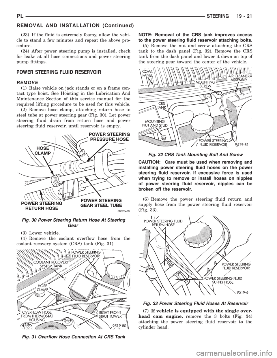
(2) Remove hose clamp, attaching return hose to
steel tube at power steering gear (Fig. 30). Let power
steering fluid drain from return hose and power
steering fluid reservoir, until reservoir is empty.
(3) Lower vehicle.
(4) Remove the coolant overflow hose from the
coolant recovery system (CRS) tank (Fig. 31).NOTE: Removal of the CRS tank improves access
to the power steering fluid reservoir attaching bolts.
(5) Remove the nut and screw attaching the CRS
tank to the dash panel (Fig. 32). Remove the CRS
tank from the dash panel and lower it down on top of
the steering gear toward the center of the vehicle.
CAUTION: Care must be used when removing and
installing power steering fluid hoses on the power
steering fluid reservoir. If excessive force is used
when trying to remove or install hoses on nipples
of power steering fluid reservoir, nipples can be
broken off the reservoir.
(6) Remove the power steering fluid return and
supply hose from the power steering fluid reservoir
(Fig. 33).
(7)If vehicle is equipped with the single over-
head cam engine,remove the 3 bolts (Fig. 34)
attaching the power steering fluid reservoir to the
cylinder head.
Fig. 30 Power Steering Return Hose At Steering
Gear
Fig. 31 Overflow Hose Connection At CRS Tank
Fig. 32 CRS Tank Mounting Bolt And Screw
Fig. 33 Power Steering Fluid Hoses At Reservoir
PLSTEERING 19 - 21
REMOVAL AND INSTALLATION (Continued)
Page 923 of 1200
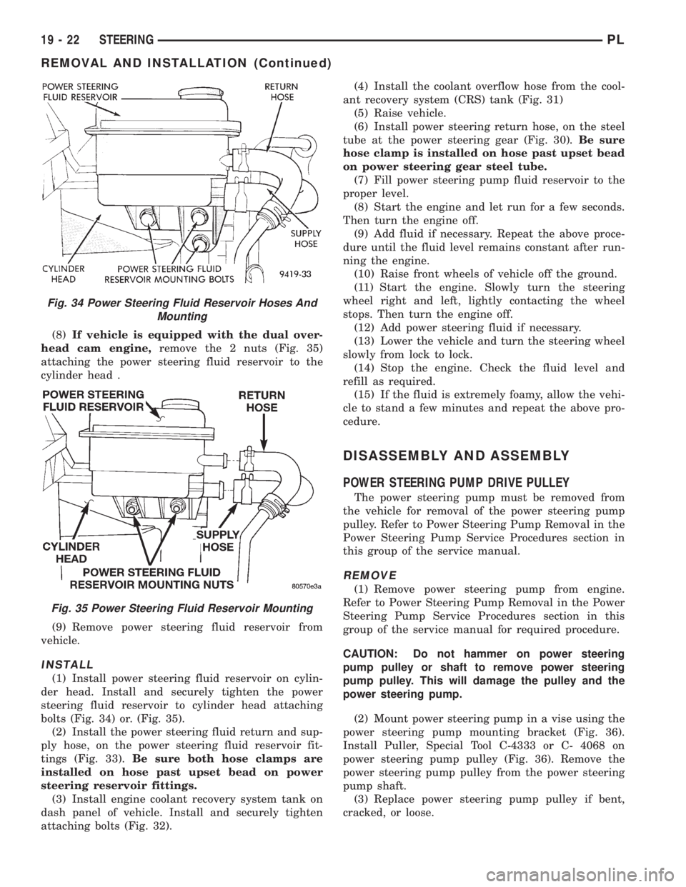
(8)If vehicle is equipped with the dual over-
head cam engine,remove the 2 nuts (Fig. 35)
attaching the power steering fluid reservoir to the
cylinder head .
(9) Remove power steering fluid reservoir from
vehicle.
INSTALL
(1) Install power steering fluid reservoir on cylin-
der head. Install and securely tighten the power
steering fluid reservoir to cylinder head attaching
bolts (Fig. 34) or. (Fig. 35).
(2) Install the power steering fluid return and sup-
ply hose, on the power steering fluid reservoir fit-
tings (Fig. 33).Be sure both hose clamps are
installed on hose past upset bead on power
steering reservoir fittings.
(3) Install engine coolant recovery system tank on
dash panel of vehicle. Install and securely tighten
attaching bolts (Fig. 32).(4) Install the coolant overflow hose from the cool-
ant recovery system (CRS) tank (Fig. 31)
(5) Raise vehicle.
(6) Install power steering return hose, on the steel
tube at the power steering gear (Fig. 30).Be sure
hose clamp is installed on hose past upset bead
on power steering gear steel tube.
(7) Fill power steering pump fluid reservoir to the
proper level.
(8) Start the engine and let run for a few seconds.
Then turn the engine off.
(9) Add fluid if necessary. Repeat the above proce-
dure until the fluid level remains constant after run-
ning the engine.
(10) Raise front wheels of vehicle off the ground.
(11) Start the engine. Slowly turn the steering
wheel right and left, lightly contacting the wheel
stops. Then turn the engine off.
(12) Add power steering fluid if necessary.
(13) Lower the vehicle and turn the steering wheel
slowly from lock to lock.
(14) Stop the engine. Check the fluid level and
refill as required.
(15) If the fluid is extremely foamy, allow the vehi-
cle to stand a few minutes and repeat the above pro-
cedure.
DISASSEMBLY AND ASSEMBLY
POWER STEERING PUMP DRIVE PULLEY
The power steering pump must be removed from
the vehicle for removal of the power steering pump
pulley. Refer to Power Steering Pump Removal in the
Power Steering Pump Service Procedures section in
this group of the service manual.
REMOVE
(1) Remove power steering pump from engine.
Refer to Power Steering Pump Removal in the Power
Steering Pump Service Procedures section in this
group of the service manual for required procedure.
CAUTION: Do not hammer on power steering
pump pulley or shaft to remove power steering
pump pulley. This will damage the pulley and the
power steering pump.
(2) Mount power steering pump in a vise using the
power steering pump mounting bracket (Fig. 36).
Install Puller, Special Tool C-4333 or C- 4068 on
power steering pump pulley (Fig. 36). Remove the
power steering pump pulley from the power steering
pump shaft.
(3) Replace power steering pump pulley if bent,
cracked, or loose.
Fig. 34 Power Steering Fluid Reservoir Hoses And
Mounting
Fig. 35 Power Steering Fluid Reservoir Mounting
19 - 22 STEERINGPL
REMOVAL AND INSTALLATION (Continued)
Page 1135 of 1200
GENERAL INFORMATION
INTRODUCTION
Both the heater and the heater/air conditioning
systems share many of the same functioning compo-
nents. This group will deal with both systems
together when component function is common, and
separately when they are not.
For proper operation of the instrument panel con-
trols, refer to the Owner's Manual provided with the
vehicle.
The unit housing is divided into two sides. The left
side is called the air distribution module. The air dis-
tribution module is the same on vehicles with or
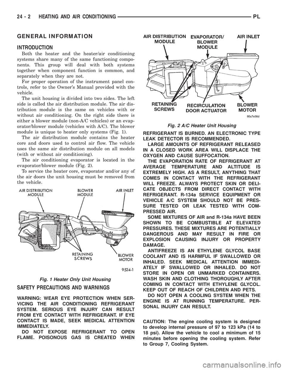
without air conditioning. On the right side there is
either a blower module (non-A/C vehicles) or an evap-
orator/blower module (vehicles with A/C). The blower
module is unique to heater only systems (Fig. 1).
The air distribution module contains the heater
core and doors used to control air flow. The vehicle
uses the same air distribution module on all models
(with or without air conditioning).
The air conditioning evaporator is located in the
evaporator/blower module (Fig. 2).
To service the heater core, evaporator and/or any of
the air doors the unit housing must be removed from
the vehicle.
SAFETY PRECAUTIONS AND WARNINGS
WARNING: WEAR EYE PROTECTION WHEN SER-
VICING THE AIR CONDITIONING REFRIGERANT
SYSTEM. SERIOUS EYE INJURY CAN RESULT
FROM EYE CONTACT WITH REFRIGERANT. IF EYE
CONTACT IS MADE, SEEK MEDICAL ATTENTION
IMMEDIATELY.
DO NOT EXPOSE REFRIGERANT TO OPEN
FLAME. POISONOUS GAS IS CREATED WHENREFRIGERANT IS BURNED. AN ELECTRONIC TYPE
LEAK DETECTOR IS RECOMMENDED.
LARGE AMOUNTS OF REFRIGERANT RELEASED
IN A CLOSED WORK AREA WILL DISPLACE THE
OXYGEN AND CAUSE SUFFOCATION.
THE EVAPORATION RATE OF REFRIGERANT AT
AVERAGE TEMPERATURE AND ALTITUDE IS
EXTREMELY HIGH. AS A RESULT, ANYTHING THAT
COMES IN CONTACT WITH THE REFRIGERANT
WILL FREEZE. ALWAYS PROTECT SKIN OR DELI-
CATE OBJECTS FROM DIRECT CONTACT WITH
REFRIGERANT. R-134a SERVICE EQUIPMENT OR
VEHICLE A/C SYSTEM SHOULD NOT BE PRES-
SURE TESTED OR LEAK TESTED WITH COM-
PRESSED AIR.
SOME MIXTURES OF AIR and R-134a HAVE BEEN
SHOWN TO BE COMBUSTIBLE AT ELEVATED
PRESSURES. THESE MIXTURES ARE POTENTIALLY
DANGEROUS AND MAY RESULT IN FIRE OR
EXPLOSION CAUSING INJURY OR PROPERTY
DAMAGE.
ANTIFREEZE IS AN ETHYLENE GLYCOL BASE
COOLANT AND IS HARMFUL IF SWALLOWED OR
INHALED. SEEK MEDICAL ATTENTION IMMEDI-
ATELY IF SWALLOWED OR INHALED. DO NOT
STORE IN OPEN OR UNMARKED CONTAINERS.
WASH SKIN AND CLOTHING THOROUGHLY AFTER
COMING IN CONTACT WITH ETHYLENE GLYCOL.
KEEP OUT OF REACH OF CHILDREN AND PETS.
DO NOT OPEN A COOLING SYSTEM WHEN THE
ENGINE IS AT RUNNING TEMPERATURE. PER-
SONAL INJURY CAN RESULT.
CAUTION: The engine cooling system is designed
to develop internal pressure of 97 to 123 kPa (14 to
18 psi). Allow the vehicle to cool a minimum of 15
minutes before opening the cooling system. Refer
to Group 7, Cooling System.
Fig. 2 A/C Heater Unit Housing
Fig. 1 Heater Only Unit Housing
24 - 2 HEATING AND AIR CONDITIONINGPL
Page 1141 of 1200
(3) Close all doors, windows and vents to the pas-
senger compartment.
(4) Set Heater-A/C control to A/C, full heat, floor,
RECIRC. and high blower.
(5) Start the engine and hold the idle speed (1000
rpm). After the engine has reached running temper-
ature, allow the passenger compartment to heat up.
This will create the need for maximum refrigerant
flow into the evaporator.
(6) If the refrigerant charge is sufficient, discharge
(high pressure) gauge should read 965 to 2620 kPa
(140 to 380 psi). Suction (low pressure) gauge should
read 103 to 2417 kPa (15 to 35 psi). If system cannot
achieve proper pressure readings, replace the expan-
sion valve. If pressure is correct, proceed with test.
WARNING: PROTECT SKIN AND EYES FROM CON-
TACTING CO2 PERSONAL INJURY CAN RESULT.
(7) If suction side low pressure is within specified
range, freeze the expansion valve control head (Fig.
10) for 30 seconds. Use a super cold substance (liquid
CO2).Do not spray refrigerant on the expansion
valve for this test.Suction side low pressure should
drop to 34.5 kPa (5 psi) If not, replace expansion
valve.
(8) Allow expansion valve to thaw. The low pres-
sure gauge reading should stabilize at 103 to 241
kPa (15 to 35 psi). If not, replace expansion valve.
(9) When expansion valve test is complete, test
A/C overall performance. Refer to the Heater and A/C
Performance Test in this section. Remove all test
equipment before returning vehicle to use.
BLOWER MOTOR ELECTRICAL DIAGNOSIS
Refer to the Blower Motor Electrical System Diag-
nosis chart in this section. Also refer to Group 8W,
Wiring Diagrams for more information.
BLOWER MOTOR VIBRATION AND/OR NOISE
DIAGNOSIS
The resistor block supplies the blower motor with
varied voltage (low and middle speeds) or battery
voltage (high speed).
CAUTION: Stay clear of the blower motor and resis-
tor block (Hot). Do not operate the blower motor
with the resistor block removed from the heater-A/C
housing.
Refer to the Blower Motor Vibration/Noise chart
for diagnosis.
EVAPORATOR PROBE TEST
The work area and vehicle must be between 16É C
(60É F) and 32É C (90É F) when testing the switch.(1) Disconnect the three wire connector from the
evaporator probe lead located behind the glove box.
(2) Start engine and set A/C to low blower motor
speed, panel, full cool, and RECIRC.
(3) Using a voltmeter, check for battery voltage
between Pin 1 and 2. If no voltage is detected, there
is no power to the switch. Check wiring and fuses.
Refer to Group 8W, Wiring Diagrams for circuit diag-
nosis.
(4) Using a voltmeter, check for battery voltage
between Pin 1 and Pin 3. If no voltage is detected,
there is no voltage from the Powertrain Control Mod-
ule. Refer to Group 8W, Wiring Diagrams. If voltage
is OK, connect a jumper wire between Pin 1 and Pin
3. The compressor clutch should engage. If the clutch
engages, remove the jumper wire immediately and go
to Step 5. If the compressor clutch does not engage,
check the operation of the clutch and repair as nec-
essary.
(5) If compressor clutch engages, connect the evap-
orator probe 3-way connector. The compressor clutch
should engage or cycle depending on evaporator tem-
perature. If OK, go to Step 6. If not OK, replace the
clutch cycling switch.
(6) The engine running and the A/C set to:
²Blower motor on low speed
²Panel position
²Full cool
²RECIRC.
Close all doors and windows. Place a thermometer
in the center discharge vent.
(7) If the clutch does not begin to cycle off between
2É C to 7É C (35É F to 45É F), verify that the evapo-
rator probe is fully installed and not loose in evapo-
rator. If it is not properly installed, install probe and
retest outlet temperature. If the evaporator probe is
properly installed, replace the clutch cycling switch.
HEATER PERFORMANCE TEST
PRE-DIAGNOSTIC PREPARATIONS
Review Safety Precautions and Warnings in this
group before performing the following procedures.
Check the coolant level, drive belt tension, vacuum
line connections, radiator air flow and fan operation.
Start engine and allow to warm up to normal tem-
perature.
WARNING: DO NOT REMOVE RADIATOR CAP
WHEN ENGINE IS HOT, PERSONAL INJURY CAN
RESULT.
If vehicle has been run recently, wait 15 minutes
before removing cap. Place a rag over the cap and
turn it to the first safety stop. Allow pressure to
escape through the overflow tube. When the system
stabilizes, remove the cap completely.
24 - 8 HEATING AND AIR CONDITIONINGPL
DIAGNOSIS AND TESTING (Continued)
Page 1144 of 1200

MAXIMUM HEATER OUTPUT: TEST AND
ACTION
Engine coolant is provided to the heater system by
two 16 mm (5/8 inch inside diameter) heater hoses.
With engine idling at normal running temperature,
set the control to maximum heat, floor, and high
blower setting. Using a test thermometer, check the
air temperature coming from the floor outlets, refer
to Temperature Reference Table.
If the floor outlet air temperature is insufficient,
refer to Group 7, Cooling Systems for specifications.
Both heater hoses should be HOT to the touch (cool-
ant return hose should be slightly cooler than the
supply hose). If coolant return hose is much cooler
than the supply hose, locate and repair engine cool-
ant flow obstruction in heater system.
POSSIBLE LOCATIONS OR CAUSE OF
OBSTRUCTED COOLANT FLOW
(1) Pinched or kinked heater hoses.
(2) Improper heater hose routing.
(3) Plugged heater hoses or supply and return
ports at cooling system connections, refer to Group 7,
Cooling System.(4) Plugged heater core.
(5) Air locked heater core.
(6) If coolant flow is verified and outlet tempera-
ture is insufficient, a mechanical problem may exist.
POSSIBLE LOCATION OR CAUSE OF
INSUFFICIENT HEAT
(1) Obstructed cowl air intake.
(2) Obstructed heater system outlets.
(3) Blend-air door not functioning properly.
TEMPERATURE CONTROL
If temperature cannot be adjusted with the TEMP
lever on the control panel, the following could require
service:
(1) Blend-air door binding.
(2) Faulty blend-air door cable.
(3) Improper engine coolant temperature.
(4) Faulty Instrument Panel Control.
LOW PRESSURE CUT-OFF SWITCH
The work area must not be below 21ÉC (70ÉF) to
test the compressor clutch circuit.
(1) With gear selector in park or neutral and park
brake set, start engine and allow to idle.
(2) Raise hood and disconnect low pressure cut off
switch connector boot.
(3) Using a suitable jumper wire, jump across the
terminals inside wire connector boot.
(4) If the compressor clutch does not engage, the
cycling clutch switch, wiring, relay, or fuse can be
defective. Refer to Group 8W, Wiring Diagrams.
(5) If clutch engages, connect manifold gauge set.
Read low pressure gauge. At pressure above 97 kPa
(14 psi) and above, low pressure out off switch will
complete the clutch circuit. If the low pressure gauge
reads below 140 kPa (20 psi), the system is low on
refrigerant charge or empty due to a leak. Refer to
Service±Procedures, System Leak Checking in this
section.
(6) Install connector boot on switch and repeat
Step 3. If the clutch does not engage, replace the low
pressure cut off switch.
SYSTEM CHARGE LEVEL TEST
The procedure below should be used to check
and/or fill the refrigerant charge in the air condition-
ing system.
Fig. 11 Evaporator Probe Harness Connector
TEMPERATURE REFERENCE TABLE
Ambient Temp.Minimum
FloorOutlet
Temp.
Celsius Fahrenheit Celsius Fahrenheit
15.5É 60É 62.2É 144É
21.1É 70É 63.8É 147É
26.6É 80É 65.5É 150É
32.2É 90É 67.2É 153É
PLHEATING AND AIR CONDITIONING 24 - 11
DIAGNOSIS AND TESTING (Continued)
Page 1157 of 1200
(3) Pull switch out of manifold.
INSTALLATION
For installation, reverse the above procedures.
HIGH PRESSURE RELIEF VALVE
WARNING: AVOID BREATHING A/C REFRIGERANT
AND LUBRICANT VAPOR OR MIST. EXPOSURE MAY
IRRITATE EYES, NOSE AND THROAT. USE ONLY
APPROVED SERVICE EQUIPMENT MEETING SAE
REQUIREMENTS TO DISCHARGE R-134a SYSTEM.
IF ACCIDENTAL SYSTEM DISCHARGE OCCURS,
VENTILATE WORK AREA BEFORE RESUMING SER-
VICE.
R-134a SERVICE EQUIPMENT OR VEHICLE A/C
SYSTEM SHOULD NOT BE PRESSURE TESTED OR
LEAK TESTED WITH COMPRESSED AIR. MIXTURE
OF AIR and R-134a CAN BE COMBUSTIBLE AT ELE-
VATED PRESSURES. THESE MIXTURES ARE
POTENTIALLY DANGEROUS AND MAY RESULT IN
FIRE OR EXPLOSION CAUSING INJURY OR PROP-
ERTY DAMAGE.
REMOVAL
(1) Using a R-134a refrigerant recovery machine,
remove the refrigerant from A/C system.
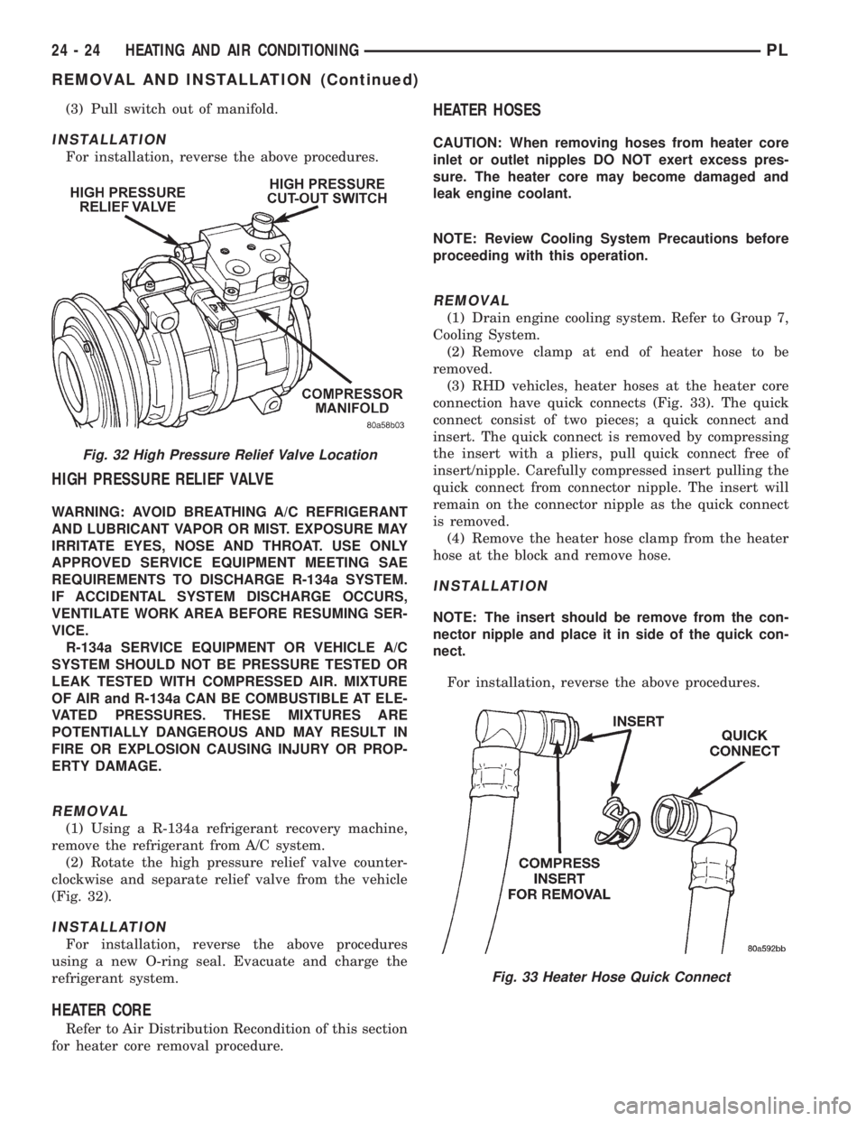
(2) Rotate the high pressure relief valve counter-
clockwise and separate relief valve from the vehicle
(Fig. 32).
INSTALLATION
For installation, reverse the above procedures
using a new O-ring seal. Evacuate and charge the
refrigerant system.
HEATER CORE
Refer to Air Distribution Recondition of this section
for heater core removal procedure.
HEATER HOSES
CAUTION: When removing hoses from heater core
inlet or outlet nipples DO NOT exert excess pres-
sure. The heater core may become damaged and
leak engine coolant.
NOTE: Review Cooling System Precautions before
proceeding with this operation.
REMOVAL
(1) Drain engine cooling system. Refer to Group 7,
Cooling System.
(2) Remove clamp at end of heater hose to be
removed.
(3) RHD vehicles, heater hoses at the heater core
connection have quick connects (Fig. 33). The quick
connect consist of two pieces; a quick connect and
insert. The quick connect is removed by compressing
the insert with a pliers, pull quick connect free of
insert/nipple. Carefully compressed insert pulling the
quick connect from connector nipple. The insert will
remain on the connector nipple as the quick connect
is removed.
(4) Remove the heater hose clamp from the heater
hose at the block and remove hose.
INSTALLATION
NOTE: The insert should be remove from the con-
nector nipple and place it in side of the quick con-
nect.
For installation, reverse the above procedures.
Fig. 33 Heater Hose Quick Connect
Fig. 32 High Pressure Relief Valve Location
24 - 24 HEATING AND AIR CONDITIONINGPL
REMOVAL AND INSTALLATION (Continued)
Page 1166 of 1200
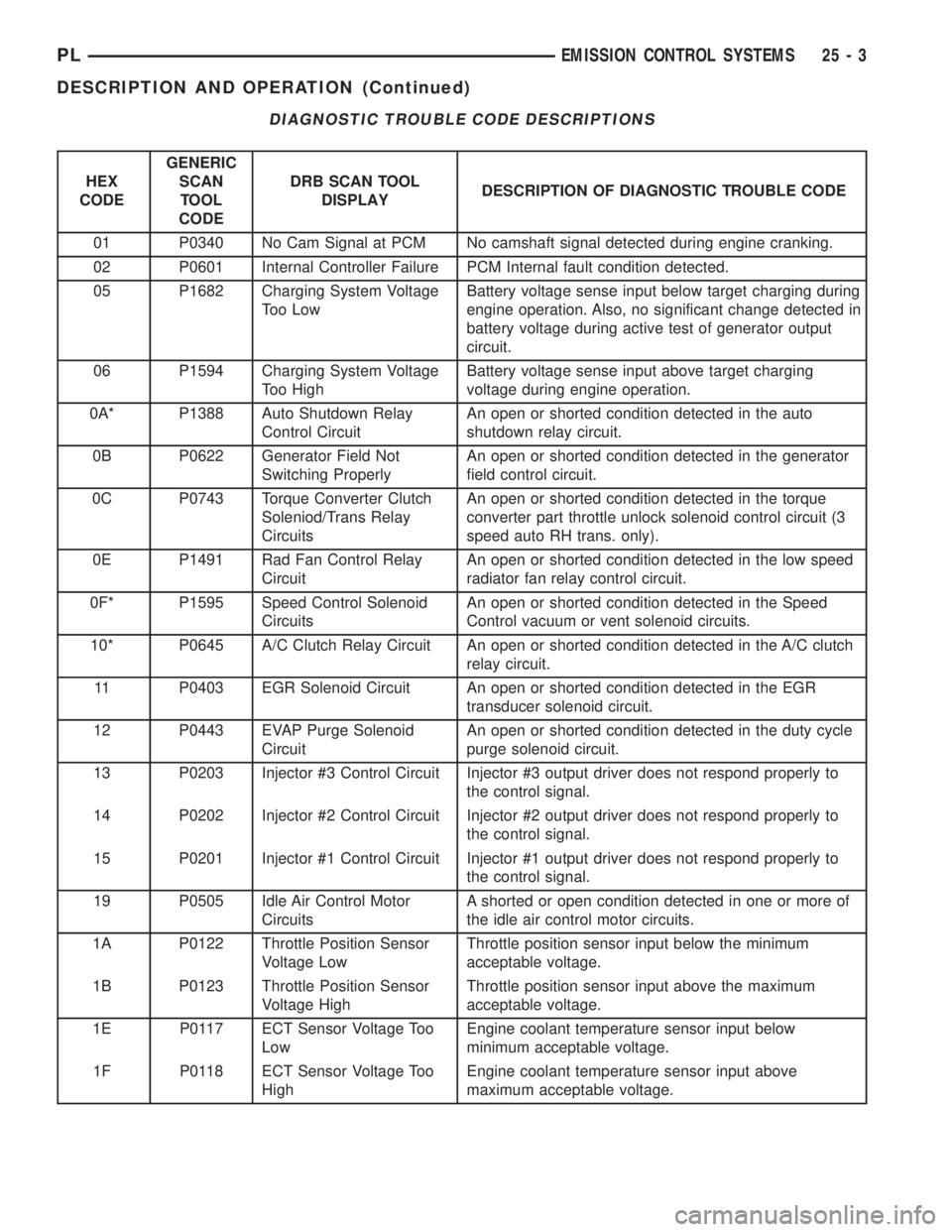
DIAGNOSTIC TROUBLE CODE DESCRIPTIONS
HEX
CODEGENERIC
SCAN
TOOL
CODEDRB SCAN TOOL
DISPLAYDESCRIPTION OF DIAGNOSTIC TROUBLE CODE
01 P0340 No Cam Signal at PCM No camshaft signal detected during engine cranking.
02 P0601 Internal Controller Failure PCM Internal fault condition detected.
05 P1682 Charging System Voltage
Too LowBattery voltage sense input below target charging during
engine operation. Also, no significant change detected in
battery voltage during active test of generator output
circuit.
06 P1594 Charging System Voltage
Too HighBattery voltage sense input above target charging
voltage during engine operation.
0A* P1388 Auto Shutdown Relay
Control CircuitAn open or shorted condition detected in the auto
shutdown relay circuit.
0B P0622 Generator Field Not
Switching ProperlyAn open or shorted condition detected in the generator
field control circuit.
0C P0743 Torque Converter Clutch
Soleniod/Trans Relay
CircuitsAn open or shorted condition detected in the torque
converter part throttle unlock solenoid control circuit (3
speed auto RH trans. only).
0E P1491 Rad Fan Control Relay
CircuitAn open or shorted condition detected in the low speed
radiator fan relay control circuit.
0F* P1595 Speed Control Solenoid
CircuitsAn open or shorted condition detected in the Speed
Control vacuum or vent solenoid circuits.
10* P0645 A/C Clutch Relay Circuit An open or shorted condition detected in the A/C clutch
relay circuit.
11 P0403 EGR Solenoid Circuit An open or shorted condition detected in the EGR
transducer solenoid circuit.
12 P0443 EVAP Purge Solenoid
CircuitAn open or shorted condition detected in the duty cycle
purge solenoid circuit.
13 P0203 Injector #3 Control Circuit Injector #3 output driver does not respond properly to
the control signal.
14 P0202 Injector #2 Control Circuit Injector #2 output driver does not respond properly to
the control signal.
15 P0201 Injector #1 Control Circuit Injector #1 output driver does not respond properly to
the control signal.
19 P0505 Idle Air Control Motor
CircuitsA shorted or open condition detected in one or more of
the idle air control motor circuits.
1A P0122 Throttle Position Sensor
Voltage LowThrottle position sensor input below the minimum
acceptable voltage.
1B P0123 Throttle Position Sensor
Voltage HighThrottle position sensor input above the maximum
acceptable voltage.
1E P0117 ECT Sensor Voltage Too
LowEngine coolant temperature sensor input below
minimum acceptable voltage.
1F P0118 ECT Sensor Voltage Too
HighEngine coolant temperature sensor input above
maximum acceptable voltage.
PLEMISSION CONTROL SYSTEMS 25 - 3
DESCRIPTION AND OPERATION (Continued)
Page 1172 of 1200
system begins to pump up to this pressure. As the
pressure increases, the cycle rate starts to drop off. If
there is no leak in the system, the pump would even-
tually stop pumping at the equalized pressure. If
there is a leak, it will continue to pump at a rate rep-
resentative of the flow characteristic of the size of the
leak. From this information we can determine if the
leak is larger than the required detection limit (cur-
rently set at .020º orifice by CARB). If a leak is
revealed during the leak test portion of the test, the
test is terminated at the end of the test mode and no
further system checks will be performed.
After passing the leak detection phase of the test,
system pressure is maintained by turning on the
LDP's solenoid until the purge system is activated.
Purge activation in effect creates a leak. The cycle
rate is again interrogated and when it increases due
to the flow through the purge system, the leak check
portion of the diagnostic is complete.
The canister vent valve will unseal the system
after completion of the test sequence as the pump
diaphragm assembly moves to the full travel position.
Evaporative system functionality will be verified by
using the stricter evap purge flow monitor. At an
appropriate warm idle the LDP will be energized to
seal the canister vent. The purge flow will be clocked
up from some small value in an attempt to see a
shift in the 02 control system. If fuel vapor, indicated
by a shift in the 02 control, is present the test is
passed. If not, it is assumed that the purge system is
not functioning in some respect. The LDP is again
turned off and the test is ended.
TRIP DEFINITION
A ªTripº means vehicle operation (following an
engine-off period) of duration and driving mode such
that all components and systems are monitored at
least once by the diagnostic system. The monitors
must successfully pass before the PCM can verify
that a previously malfunctioning component is meet-
ing the normal operating conditions of that compo-
nent. For misfire or fuel system malfunction, the
MIL may be extinguished if the fault does not recur
when monitored during three subsequent sequential
driving cycles in which conditions are similar to
those under which the malfunction was first deter-
mined.
Anytime the MIL is illuminated, a DTC is stored.
The DTC can self erase only when the MIL has been
extinguished. Once the MIL is extinguished, the
PCM must pass the diagnostic test for the most
recent DTC for 40 warm-up cycles (80 warm-up
cycles for the Fuel System Monitor and the Misfire
Monitor). A warm-up cycle can best be described by
the following:
²The engine must be running²A rise of 40ÉF in engine temperature must occur
from the time when the engine was started
²Engine coolant temperature must reach at least
160ÉF
²A ªdriving cycleº that consists of engine start up
and engine shut off.
Once the above conditions occur, the PCM is con-
sidered to have passed a warm-up cycle. Due to the
conditions required to extinguish the MIL and erase
the DTC, it is most important that after a repair has
been made, all DTC's be erased and the repair veri-
fied.
COMPONENT MONITORS
There are several components that will affect vehi-
cle emissions if they malfunction. If one of these com-
ponents malfunctions the Malfunction Indicator
Lamp (Check Engine) will illuminate.
Some of the component monitors are checking for
proper operation of the part. Electrically operated
components now have input (rationality) and output
(functionality) checks. Previously, a component like
the Throttle Position sensor (TPS) was checked by
the PCM for an open or shorted circuit. If one of
these conditions occurred, a DTC was set. Now there
is a check to ensure that the component is working.
This is done by watching for a TPS indication of a
greater or lesser throttle opening than MAP and
engine rpm indicate. In the case of the TPS, if engine
vacuum is high and engine rpm is 1600 or greater
and the TPS indicates a large throttle opening, a
DTC will be set. The same applies to low vacuum
and 1600 rpm.
Any component that has an associated limp in will
set a fault after 1 trip with the malfunction present.
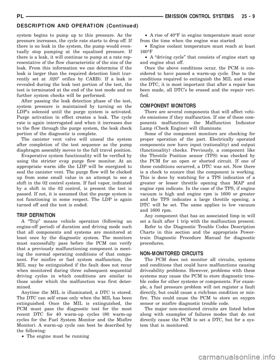
Refer to the Diagnostic Trouble Codes Description
Charts in this section and the appropriate Power-
train Diagnostic Procedure Manual for diagnostic
procedures.
NON-MONITORED CIRCUITS
The PCM does not monitor all circuits, systems
and conditions that could have malfunctions causing
driveability problems. However, problems with these
systems may cause the PCM to store diagnostic trou-
ble codes for other systems or components. For exam-
ple, a fuel pressure problem will not register a fault
directly, but could cause a rich/lean condition or mis-
fire. This could cause the PCM to store an oxygen
sensor or misfire diagnostic trouble code.
The major non-monitored circuits are listed below
along with examples of failures modes that do not
directly cause the PCM to set a DTC, but for a sys-
tem that is monitored.
PLEMISSION CONTROL SYSTEMS 25 - 9
DESCRIPTION AND OPERATION (Continued)