1999 DODGE NEON maintenance
[x] Cancel search: maintenancePage 1084 of 1200
DIAGNOSIS AND TESTING
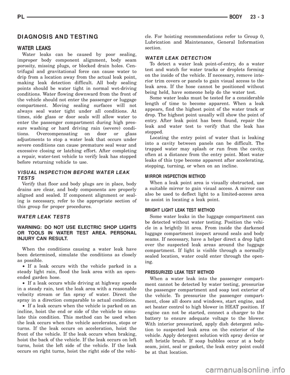
WATER LEAKS
Water leaks can be caused by poor sealing,
improper body component alignment, body seam
porosity, missing plugs, or blocked drain holes. Cen-
trifugal and gravitational force can cause water to
drip from a location away from the actual leak point,
making leak detection difficult. All body sealing
points should be water tight in normal wet-driving
conditions. Water flowing downward from the front of
the vehicle should not enter the passenger or luggage
compartment. Moving sealing surfaces will not
always seal water tight under all conditions. At
times, side glass or door seals will allow water to
enter the passenger compartment during high pres-
sure washing or hard driving rain (severe) condi-
tions. Overcompensating on door or glass
adjustments to stop a water leak that occurs under
severe conditions can cause premature seal wear and
excessive closing or latching effort. After completing
a repair, water-test vehicle to verify leak has stopped
before returning vehicle to use.
VISUAL INSPECTION BEFORE WATER LEAK
TESTS
Verify that floor and body plugs are in place, body
drains are clear, and body components are properly
aligned and sealed. If component alignment or seal-
ing is necessary, refer to the appropriate section of
this group for proper procedures.
WATER LEAK TESTS
WARNING: DO NOT USE ELECTRIC SHOP LIGHTS
OR TOOLS IN WATER TEST AREA. PERSONAL
INJURY CAN RESULT.
When the conditions causing a water leak have
been determined, simulate the conditions as closely
as possible.
²If a leak occurs with the vehicle parked in a
steady light rain, flood the leak area with an open-
ended garden hose.
²If a leak occurs while driving at highway speeds
in a steady rain, test the leak area with a reasonable
velocity stream or fan spray of water. Direct the
spray in a direction comparable to actual conditions.
²If a leak occurs when the vehicle is parked on an
incline, hoist the end or side of the vehicle to simu-
late this condition. This method can be used when
the leak occurs when the vehicle accelerates, stops or
turns. If the leak occurs on acceleration, hoist the
front of the vehicle. If the leak occurs when braking,
hoist the back of the vehicle. If the leak occurs on left
turns, hoist the left side of the vehicle. If the leak
occurs on right turns, hoist the right side of the vehi-cle. For hoisting recommendations refer to Group 0,
Lubrication and Maintenance, General Information
section.
WATER LEAK DETECTION
To detect a water leak point-of-entry, do a water
test and watch for water tracks or droplets forming
on the inside of the vehicle. If necessary, remove inte-
rior trim covers or panels to gain visual access to the
leak area. If the hose cannot be positioned without
being held, have someone help do the water test.
Some water leaks must be tested for a considerable
length of time to become apparent. When a leak
appears, find the highest point of the water track or
drop. The highest point usually will show the point of
entry. After leak point has been found, repair the
leak and water test to verify that the leak has
stopped.
Locating the entry point of water that is leaking
into a cavity between panels can be difficult. The
trapped water may splash or run from the cavity,
often at a distance from the entry point. Most water
leaks of this type become apparent after accelerating,
stopping, turning, or when on an incline.
MIRROR INSPECTION METHOD
When a leak point area is visually obstructed, use
a suitable mirror to gain visual access. A mirror can
also be used to deflect light to a limited-access area
to assist in locating a leak point.
BRIGHT LIGHT LEAK TEST METHOD
Some water leaks in the luggage compartment can
be detected without water testing. Position the vehi-
cle in a brightly lit area. From inside the darkened
luggage compartment inspect around seals and body
seams. If necessary, have a helper direct a drop light
over the suspected leak areas around the luggage
compartment. If light is visible through a normally
sealed location, water could enter through the open-
ing.
PRESSURIZED LEAK TEST METHOD
When a water leak into the passenger compart-
ment cannot be detected by water testing, pressurize
the passenger compartment and soap test exterior of
the vehicle. To pressurize the passenger compart-
ment, close all doors and windows, start engine, and
set heater control to high blower in HEAT position. If
engine can not be started, connect a charger to the
battery to ensure adequate voltage to the blower.
With interior pressurized, apply dish detergent solu-
tion to suspected leak area on the exterior of the
vehicle. Apply detergent solution with spray device or
soft bristle brush. If soap bubbles occur at a body
seam, joint, seal or gasket, the leak entry point could
be at that location.
PLBODY 23 - 3
Page 1137 of 1200
COMPRESSOR
The compressor used on this vehicle is a Nippon-
denso 10PA17 R-134a. This compressor uses an alu-
minum swash plate, teflon coated pistons and
aluminum sleeved cylinder walls.
CAUTION: A 10PA17 R-12 compressor looks identi-
cal to a 10PA17 R-134a and will bolt up to the vehi-
cle. The 10PA17 R-12 compressor must not be used
on this system. It is extremely important that a
10PA17 R-134a compressor is identified prior to
using compressor in question. Check tag located
on compressor for model number.
NOISE
Excessive noise that occurs when the air condition-
ing is being used may be caused by:
²Loose bolts
²Mounting brackets
²Loose compressor clutch
²Excessive high refrigerant operating pressure
Verify the following before compressor repair is
performed:
(1) Compressor drive belt condition
(2) Proper refrigerant charge
(3) Thermal expansion valve (TXV) operating cor-
rectly
(4) Head pressure is normal
COMPRESSOR FRONT SHAFT SEAL
The compressor front shaft seal is not serviceable.
If a leak is detected at the shaft seal, the compressor
must be replaced as a unit.
CONDENSATION DRAIN TUBE
Condensation that accumulates in the evaporator
housing is drained from a tube through the dash and
on to the ground. This tube must be kept open to
prevent condensate water from collecting in the bot-
tom of the housing.
The tapered end of the drain tube is designed to
keep contaminants from entering the heater A/C unit
housing. If the tube is pinched or blocked, condensate
cannot drain, causing water to back up and spill into
the passenger compartment. It is normal to see con-
densate drainage below the vehicle. If the tube is
damaged, it should be replaced.
ENGINE COOLING SYSTEM REQUIREMENTS
To maintain ample temperature levels from the
heating-A/C system, the cooling system must be in
proper working order. Refer to Group 0, Lubrication
and Maintenance or Group 7, Cooling System of this
manual.
The use of a bug screen is not recommended. Any
obstructions forward of the condenser can reduce the
effectiveness of the air conditioning system.
EVAPORATOR PROBE
The evaporator probe can be replaced without hav-
ing to remove the unit housing from the vehicle.
The evaporator probe is located in the unit housing
and placed in the evaporator fins. The probe prevents
evaporator freeze-up. This is done by cycling the com-
pressor clutch OFF when evaporator temperature
drops below freeze point. It cycles ON when the
evaporator temperature rises above freeze point. The
evaporator probe uses a thermistor probe in a capil-
lary tube. The tube is inserted between the evapora-
tor fins in the heater-A/C unit housing.
HANDLING TUBING AND FITTINGS
Kinks in the refrigerant tubing or sharp bends in
the refrigerant hose lines will greatly reduce the
capacity of the entire system. High pressures are pro-
duced in the system when it is operating. Extreme
care must be exercised to make sure that all connec-
tions are pressure tight. Dirt and moisture can enter
the system when it is opened for repair or replace-
ment of lines or components. The refrigerant oil will
absorb moisture readily out of the air. This moisture
will convert into acids within a closed system.
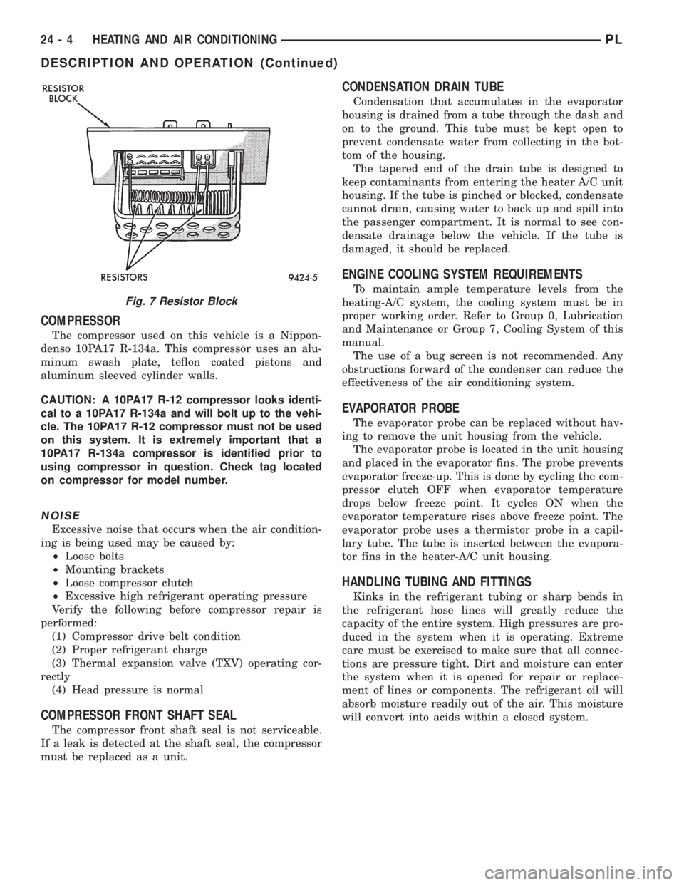
Fig. 7 Resistor Block
24 - 4 HEATING AND AIR CONDITIONINGPL
DESCRIPTION AND OPERATION (Continued)
Page 1174 of 1200
EVAPORATIVE EMISSION CONTROLS
INDEX
page page
DESCRIPTION AND OPERATION
DUTY CYCLE EVAP PURGE SOLENOID VALVE . 11
EVAP CANISTER........................ 11
EVAPORATION CONTROL SYSTEM.......... 11
LEAK DETECTION PUMP................. 12
POSITIVE CRANKCASE VENTILATION (PCV)
SYSTEMS............................ 12
PRESSURE-VACUUM FILLER CAP.......... 12
ROLLOVER VALVE....................... 11VEHICLE EMISSION CONTROL INFORMATION
LABEL............................... 13
DIAGNOSIS AND TESTING
LEAK DETECTION PUMP................. 14
PCV VALVE TEST....................... 14
VACUUM SCHEMATIC.................... 14
REMOVAL AND INSTALLATION
LEAK DETECTION PUMP REPLACEMENT.... 17
DESCRIPTION AND OPERATION
EVAPORATION CONTROL SYSTEM
The evaporation control system prevents the emis-
sion of fuel tank vapors into the atmosphere. When
fuel evaporates in the fuel tank, the vapors pass
through vent hoses or tubes to a charcoal filled evap-
orative canister. The canister temporarily holds the
vapors. The Powertrain Control Module (PCM) allows
intake manifold vacuum to draw vapors into the com-
bustion chambers during certain operating condi-
tions.
All engines use a proportional purge system. The
PCM controls vapor flow by operating the purge sole-
noid. Refer to Proportional Purge Solenoid in this
section.
NOTE: The evaporative system uses specially man-
ufactured hoses. If they need replacement, only use
fuel resistant hose.
ROLLOVER VALVE
All vehicles have a rollover valve. The valve also
prevents fuel flow through the fuel tank vent valve
hoses should the vehicle rollover. All vehicles pass a
360É rollover.
The charcoal filled evaporative canister stores the
vapors. The rollover valve is not a serviceable item.
EVAP CANISTER
All vehicles use a sealed, maintenance free, evapo-
rative (EVAP) canister. Fuel tank pressure vents into
the canister. The canister temporarily holds the fuel
vapors until intake manifold vacuum draws them
into the combustion chamber. The PCM purges the
canister through the duty cycle EVAP purge solenoid.
The PCM purges the canister at predetermined inter-
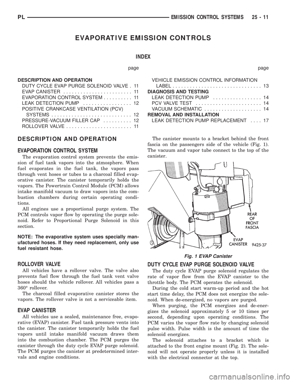
vals and engine conditions.The canister mounts to a bracket behind the front
fascia on the passengers side of the vehicle (Fig. 1).
The vacuum and vapor tube connect to the top of the
canister.
DUTY CYCLE EVAP PURGE SOLENOID VALVE
The duty cycle EVAP purge solenoid regulates the
rate of vapor flow from the EVAP canister to the
throttle body. The PCM operates the solenoid.
During the cold start warm-up period and the hot
start time delay, the PCM does not energize the sole-
noid. When de-energized, no vapors are purged.
When purging, the PCM energizes and de-ener-
gizes the solenoid approximately 5 or 10 times per
second, depending upon operating conditions. The
PCM varies the vapor flow rate by changing solenoid
pulse width. Pulse width is the amount of time the
solenoid energizes.
The solenoid attaches to a bracket which is
attached to the front engine mount (Fig. 2). The sole-
noid will not operate properly unless it is installed
with the electrical connector at the top.
Fig. 1 EVAP Canister
PLEMISSION CONTROL SYSTEMS 25 - 11
Page 1195 of 1200
METRIC SYSTEM
WARNING: USE OF AN INCORRECT FASTENER
MAY RESULT IN COMPONENT DAMAGE OR PER-
SONAL INJURY.
Figure art, specifications and torque references in
this Service Manual are identified in metric and SAE
format.
During any maintenance or repair procedures, it is
important to salvage metric fasteners (nuts, bolts,
etc.) for reassembly. If the fastener is not salvage-
able, a fastener of equivalent specification should be
used.
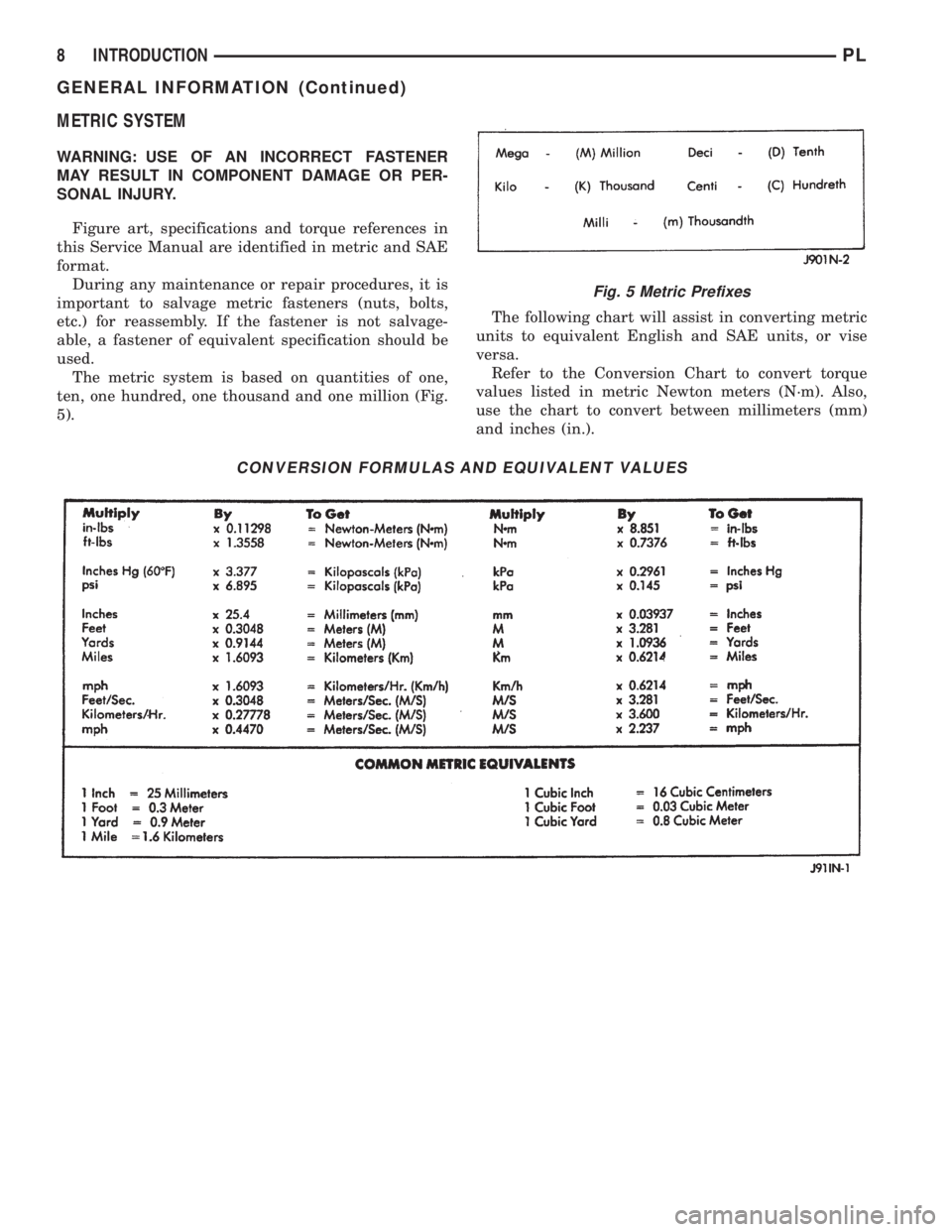
The metric system is based on quantities of one,
ten, one hundred, one thousand and one million (Fig.
5).The following chart will assist in converting metric
units to equivalent English and SAE units, or vise
versa.
Refer to the Conversion Chart to convert torque
values listed in metric Newton meters (N´m). Also,
use the chart to convert between millimeters (mm)
and inches (in.).
CONVERSION FORMULAS AND EQUIVALENT VALUES
Fig. 5 Metric Prefixes
8 INTRODUCTIONPL
GENERAL INFORMATION (Continued)
Page 1200 of 1200
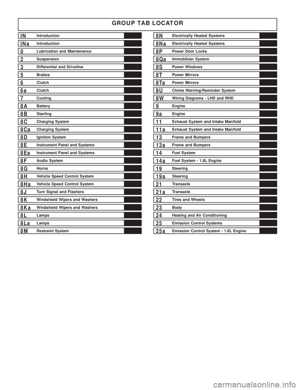
GROUP TAB LOCATOR
INIntroduction
INaIntroduction
0Lubrication and Maintenance
2Suspension
3Differential and Driveline
5Brakes
6Clutch
6aClutch
7Cooling
8ABattery
8BStarting
8CCharging System
8CaCharging System
8DIgnition System
8EInstrument Panel and Systems
8EaInstrument Panel and Systems
8FAudio System
8GHorns
8HVehicle Speed Control System
8HaVehicle Speed Control System
8JTurn Signal and Flashers
8KWindshield Wipers and Washers
8KaWindshield Wipers and Washers
8LLamps
8LaLamps
8MRestraint System
8NElectrically Heated Systems
8NaElectrically Heated Systems
8PPower Door Locks
8QaImmobilizer System
8SPower Windows
8TPower Mirrors
8TaPower Mirrors
8UChime Warning/Reminder System
8WWiring Diagrams - LHD and RHD
9Engine
9aEngine
11Exhaust System and Intake Manifold
11aExhaust System and Intake Manifold
13Frame and Bumpers
13aFrame and Bumpers
14Fuel System
14aFuel System - 1.8L Engine
19Steering
19aSteering
21Transaxle
21aTransaxle
22Tires and Wheels
23Body
24Heating and Air Conditioning
25Emission Control Systems
25aEmission Control System - 1.8L Engine