1999 DODGE NEON maintenance
[x] Cancel search: maintenancePage 147 of 1200
(3)Be sure parking brake lever is fully
released.
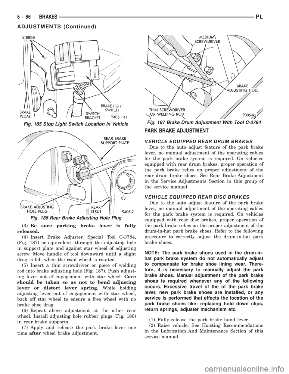
(4) Insert Brake Adjuster, Special Tool C-3784,
(Fig. 187) or equivalent, through the adjusting hole
in support plate and against star wheel of adjusting
screw. Move handle of tool downward until a slight
drag is felt when the road wheel is rotated.
(5) Insert a thin screwdriver or piece of welding
rod into brake adjusting hole (Fig. 187). Push adjust-
ing lever out of engagement with star wheel.Care
should be taken so as not to bend adjusting
lever or distort lever spring.While holding
adjusting lever out of engagement with star wheel,
back off star wheel to ensure a free wheel with no
brake shoe drag.
(6) Repeat above adjustment at the other rear
wheel. Install adjusting hole rubber plugs (Fig. 186)
in rear brake supports.
(7) Apply and release the park brake lever one
timeafterwheel brake adjustment.
PARK BRAKE ADJUSTMENT
VEHICLE EQUIPPED REAR DRUM BRAKES
Due to the auto adjust feature of the park brake
lever, no manual adjustment of the operating cables
for the park brake system is required. On vehicles
equipped with rear drum brakes, proper operation of
the park brake relies on proper adjustment of the
rear drum brake shoes. See Rear Brake Adjustment
in the Service Adjustments Section in this group of
the service manual.
VEHICLE EQUIPPED REAR DISC BRAKES
Due to the auto adjust feature of the park brake
lever, no manual adjustment of the operating cables
for the park brake system is required. On vehicles
equipped with rear disc brakes, proper operation of
the park brake relies on the proper adjustment of the
drum-in-hat park brake shoes. Refer to the following
procedure to correctly adjust the drum-in-hat park
brake shoes.
NOTE: The park brake shoes used in the drum-in-
hat park brake system do not automatically adjust
to compensate for brake shoe lining wear. There-
fore, it is necessary to manually adjust the park
brake shoes. Manual adjustment of the park brake
shoes is required whenever any of the following
occurs. Excessive travel of the of the park brake
lever, new park brake shoes are installed, or any
service is performed that effects the location of the
park brake shoes like: replacing hold down clips,
return springs, adjuster mechanism etc.
(1) Fully release the park brake hand lever.
(2) Raise vehicle. See Hoisting Recommendations
in the Lubrication And Maintenance Section of this
service manual.
Fig. 185 Stop Light Switch Location In Vehicle
Fig. 186 Rear Brake Adjusting Hole Plug
Fig. 187 Brake Drum Adjustment With Tool C-3784
5 - 66 BRAKESPL
ADJUSTMENTS (Continued)
Page 168 of 1200
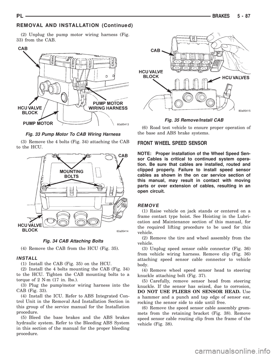
(2) Unplug the pump motor wiring harness (Fig.
33) from the CAB.
(3) Remove the 4 bolts (Fig. 34) attaching the CAB
to the HCU.
(4) Remove the CAB from the HCU (Fig. 35).
INSTALL
(1) Install the CAB (Fig. 35) on the HCU.
(2) Install the 4 bolts mounting the CAB (Fig. 34)
to the HCU. Tighten the CAB mounting bolts to a
torque of 2 N´m (17 in. lbs.).
(3) Plug the pump/motor wiring harness into the
CAB (Fig. 33).
(4) Install the ICU. Refer to ABS Integrated Con-
trol Unit in the Removal And Installation Section in
this group of the service manual for the Installation
procedure.
(5) Bleed the base brakes and the ABS brakes
hydraulic system. Refer to the Bleeding ABS System
in this section of the manual for the proper bleeding
procedure.(6) Road test vehicle to ensure proper operation of
the base and ABS brake systems.
FRONT WHEEL SPEED SENSOR
NOTE: Proper installation of the Wheel Speed Sen-
sor Cables is critical to continued system opera-
tion. Be sure that cables are installed, routed and
clipped properly. Failure to install speed sensor
cables as shown in the on car service section of
this manual, may result in contact with moving
parts or over extension of cables, resulting in an
open circuit.
REMOVE
(1) Raise vehicle on jack stands or centered on a
frame contact type hoist. See Hoisting in the Lubri-
cation and Maintenance section of this manual, for
the required lifting procedure to be used for this
vehicle.
(2) Remove the tire and wheel assembly from the
vehicle.
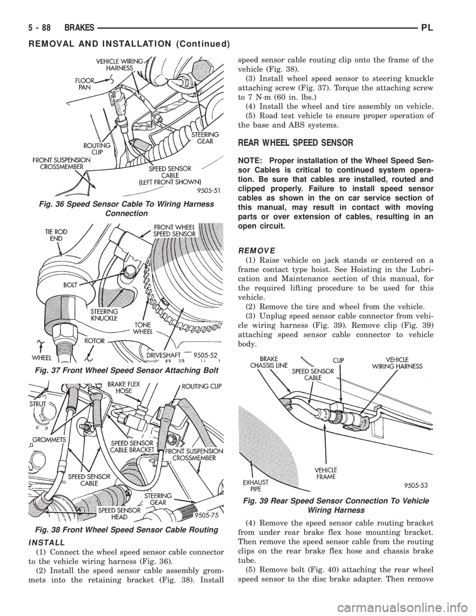
(3) Unplug speed sensor cable connector (Fig. 36)
from vehicle wiring harness. Remove clip (Fig. 36)
attaching speed sensor cable connector to vehicle
body.
(4) Remove wheel speed sensor head to steering
knuckle attaching bolt (Fig. 37).
(5) Carefully, remove sensor head from steering
knuckle. If the sensor has seized, due to corrosion,
DO NOT USE PLIERS ON SENSOR HEAD.Use
a hammer and a punch and tap edge of sensor ear,
rocking the sensor side to side until free.
(6) Remove the speed sensor cable assembly grom-
mets from the retaining bracket (Fig. 38). Remove
speed sensor cable routing clip from the frame of the
vehicle (Fig. 38).
Fig. 33 Pump Motor To CAB Wiring Harness
Fig. 34 CAB Attaching Bolts
Fig. 35 Remove/Install CAB
PLBRAKES 5 - 87
REMOVAL AND INSTALLATION (Continued)
Page 169 of 1200
INSTALL
(1) Connect the wheel speed sensor cable connector
to the vehicle wiring harness (Fig. 36).
(2) Install the speed sensor cable assembly grom-
mets into the retaining bracket (Fig. 38). Installspeed sensor cable routing clip onto the frame of the
vehicle (Fig. 38).
(3) Install wheel speed sensor to steering knuckle
attaching screw (Fig. 37). Torque the attaching screw
to 7 N´m (60 in. lbs.)
(4) Install the wheel and tire assembly on vehicle.
(5) Road test vehicle to ensure proper operation of
the base and ABS systems.
REAR WHEEL SPEED SENSOR
NOTE: Proper installation of the Wheel Speed Sen-
sor Cables is critical to continued system opera-
tion. Be sure that cables are installed, routed and
clipped properly. Failure to install speed sensor
cables as shown in the on car service section of
this manual, may result in contact with moving
parts or over extension of cables, resulting in an
open circuit.
REMOVE
(1) Raise vehicle on jack stands or centered on a
frame contact type hoist. See Hoisting in the Lubri-
cation and Maintenance section of this manual, for
the required lifting procedure to be used for this
vehicle.
(2) Remove the tire and wheel from the vehicle.
(3) Unplug speed sensor cable connector from vehi-
cle wiring harness (Fig. 39). Remove clip (Fig. 39)
attaching speed sensor cable connector to vehicle
body.
(4) Remove the speed sensor cable routing bracket
from under rear brake flex hose mounting bracket.
Then remove the speed sensor cable from the routing
clips on the rear brake flex hose and chassis brake
tube.
(5) Remove bolt (Fig. 40) attaching the rear wheel
speed sensor to the disc brake adapter. Then remove
Fig. 36 Speed Sensor Cable To Wiring Harness
Connection
Fig. 37 Front Wheel Speed Sensor Attaching Bolt
Fig. 38 Front Wheel Speed Sensor Cable Routing
Fig. 39 Rear Speed Sensor Connection To Vehicle
Wiring Harness
5 - 88 BRAKESPL
REMOVAL AND INSTALLATION (Continued)
Page 173 of 1200
The clutch cable has a unique self-adjuster mecha-
nism built into the cable which compensates for
clutch disc wear. The cable requires no maintenance
or lubrication. There are no serviceable components
on the cable assembly.
The clutch pedal is connected to the cable through
a plastic spacer. The upper end of the clutch pedal
pivots in the pedal bracket on two nylon bushings
and a shaft. These bushings are greased at assembly
and do not require periodic lubrication.
CLUTCH DISC AND COVER APPLICATION
The 2.0 single overhead cam engine uses a 216 mm
(8.5 in.) clutch disc. The manual transaxle is avail-
able only with the 2.0 liter engine.
CLUTCH REPLACEMENT
The transaxle must be removed to service the
clutch disc, pressure plate, flywheel/drive plate,
and/or clutch release bearing and lever.
DESCRIPTION AND OPERATION
CLUTCH CABLE
The manual transaxle clutch release system has a
unique self-adjusting mechanism to compensate for
clutch disc wear. This adjuster mechanism is located
within the clutch cable assembly. The preload spring
maintains tension on the cable. This tension keeps
the clutch release bearing continuously loaded
against the fingers of the clutch cover assembly.
CLUTCH PEDAL POSITION SWITCH
The clutch pedal position switch functions as a
safety interlock device. It prevents possible engine
cranking with the clutch engaged.
The clutch pedal position switch is wired in series
between the starter relay coil and the ignition
switch.
The clutch pedal position switch is mounted to a
bracket located behind the clutch pedal. The switch
is held in place by four plastic wing tabs.The clutch pedal position switch IS NOT adjust-
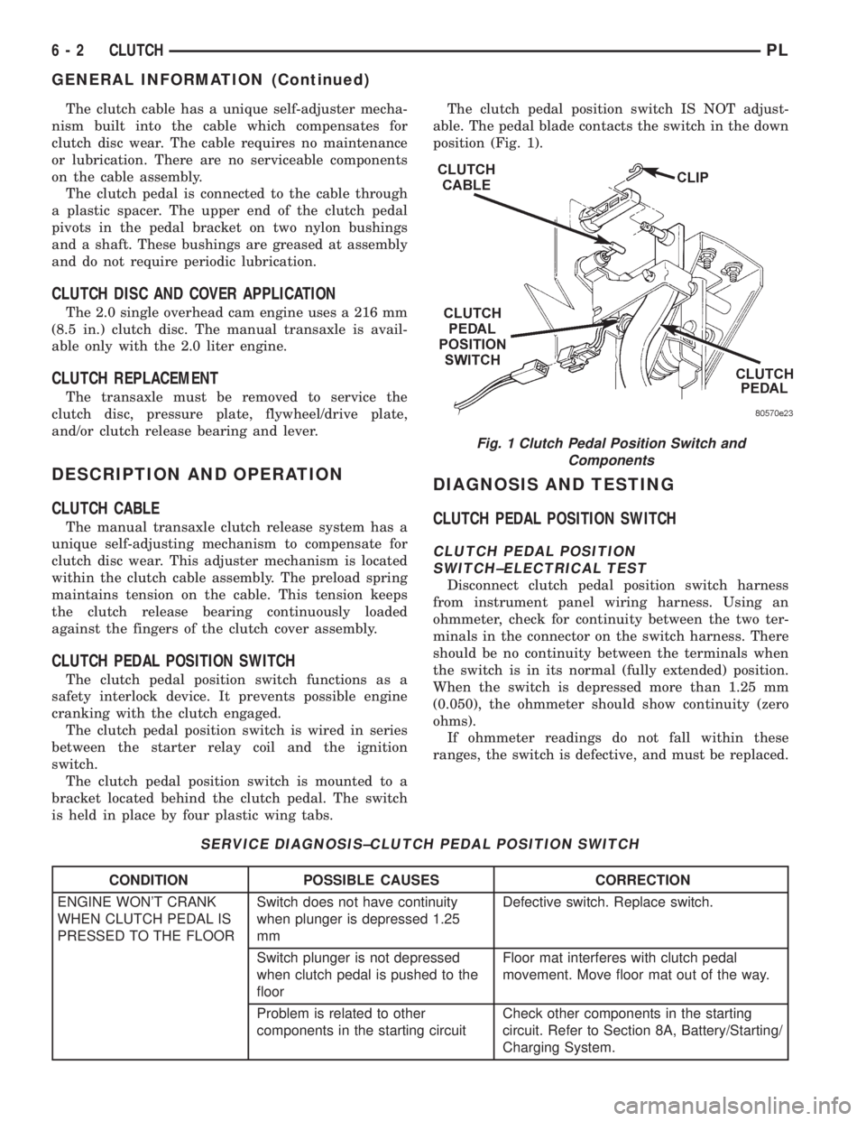
able. The pedal blade contacts the switch in the down
position (Fig. 1).
DIAGNOSIS AND TESTING
CLUTCH PEDAL POSITION SWITCH
CLUTCH PEDAL POSITION
SWITCH±ELECTRICAL TEST
Disconnect clutch pedal position switch harness
from instrument panel wiring harness. Using an
ohmmeter, check for continuity between the two ter-
minals in the connector on the switch harness. There
should be no continuity between the terminals when
the switch is in its normal (fully extended) position.
When the switch is depressed more than 1.25 mm
(0.050), the ohmmeter should show continuity (zero
ohms).
If ohmmeter readings do not fall within these
ranges, the switch is defective, and must be replaced.
SERVICE DIAGNOSIS±CLUTCH PEDAL POSITION SWITCH
CONDITION POSSIBLE CAUSES CORRECTION
ENGINE WON'T CRANK
WHEN CLUTCH PEDAL IS
PRESSED TO THE FLOORSwitch does not have continuity
when plunger is depressed 1.25
mmDefective switch. Replace switch.
Switch plunger is not depressed
when clutch pedal is pushed to the
floorFloor mat interferes with clutch pedal
movement. Move floor mat out of the way.
Problem is related to other
components in the starting circuitCheck other components in the starting
circuit. Refer to Section 8A, Battery/Starting/
Charging System.
Fig. 1 Clutch Pedal Position Switch and
Components
6 - 2 CLUTCHPL
GENERAL INFORMATION (Continued)
Page 184 of 1200
CLUTCH
CONTENTS
page page
GENERAL INFORMATION
CLUTCH COMPONENTS Ð RIGHT HAND
DRIVE (RHD)........................ 1
CLUTCH DISC AND COVER APPLICATION Ð
RIGHT HAND DRIVE (RHD)............. 1
CLUTCH REPLACEMENT Ð RIGHT HAND
DRIVE (RHD)........................ 1
DESCRIPTION AND OPERATION
CLUTCH PEDAL POSITION SWITCH Ð RIGHT
HAND DRIVE (RHD)................... 2
HYDRAULIC CLUTCH SYSTEM Ð RIGHT
HAND DRIVE (RHD)................... 2
DIAGNOSIS AND TESTING
CLASH±INTO±REVERSE COMPLAINTS...... 6CLUTCH DIAGNOSIS Ð RIGHT HAND DRIVE
(RHD).............................. 2
REMOVAL AND INSTALLATION
CLUTCH ASSEMBLY Ð RIGHT HAND DRIVE
(RHD).............................. 8
CLUTCH MASTER CYLINDER Ð RIGHT HAND
DRIVE (RHD)........................ 6
CLUTCH PEDAL POSITION SWITCH Ð RIGHT
HAND DRIVE (RHD)................... 8
HYDRAULIC SLAVE CYLINDER Ð RIGHT
HAND DRIVE (RHD)................... 7
SPECIFICATIONS
NV T350 (A-578) CLUTCH TIGHTENING
REFERENCE.......................... 9
GENERAL INFORMATION
CLUTCH COMPONENTS Ð RIGHT HAND DRIVE
(RHD)
The modular clutch assembly used in this vehicle
consists of a single, dry-type clutch disc and a dia-
phragm style clutch cover.
The clutch disc has cushion springs riveted to the
disc hub assembly. The clutch disc facings are riveted
to the cushion springs. The facings are made from a
non-asbestos material.
The clutch cover pressure plate assembly is a dia-
phragm type unit with a one-piece diaphragm spring
with multiple release fingers. The pressure plate
release fingers are preset during manufacture and
are not adjustable.
A sleeve-type release bearing is used to engage and
disengage the clutch cover pressure plate. The bear-
ing is prelubed during manufacture and is a sealed
unit.
The release bearing is operated by a pivoting
release fork in the clutch housing. The fork pivots on
a ball stud within the housing. The release fork is
actuated by a hydraulic clutch system.
The hydraulic clutch automatically adjusts for any
slack in the mechanism. This compensates for clutch
disc wear. The system requires no maintenance or
lubrication.
The clutch pedal is connected to the clutch master
cylinder through a plastic bushing. The upper end of
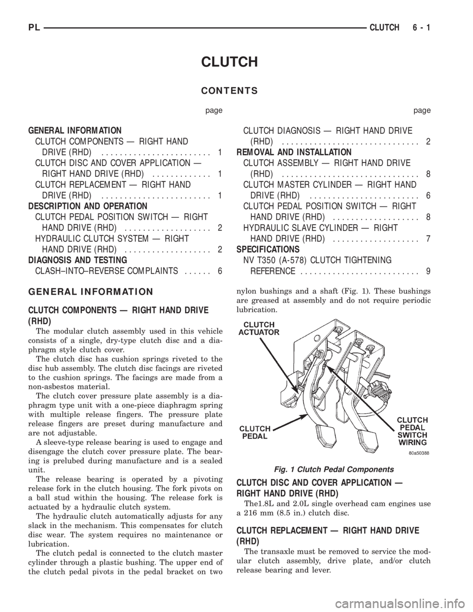
the clutch pedal pivots in the pedal bracket on twonylon bushings and a shaft (Fig. 1). These bushings
are greased at assembly and do not require periodic
lubrication.
CLUTCH DISC AND COVER APPLICATION Ð
RIGHT HAND DRIVE (RHD)
The1.8L and 2.0L single overhead cam engines use
a 216 mm (8.5 in.) clutch disc.
CLUTCH REPLACEMENT Ð RIGHT HAND DRIVE
(RHD)
The transaxle must be removed to service the mod-
ular clutch assembly, drive plate, and/or clutch
release bearing and lever.
Fig. 1 Clutch Pedal Components
PLCLUTCH 6 - 1
Page 196 of 1200
ENGINE THERMOSTAT
The engine thermostat is located on the front of
the engine (radiator side) in the thermostat housing/
engine outlet connector. The thermostat has an air
bleed (vent) located in the flange and a O-ring for
sealing incorporate on it. There is a relief in the ther-
mostat housing/outlet connector for the O-ring.
WATER PUMP
The water pump has a diecast aluminum body and
housing with a stamped steel impeller. The water
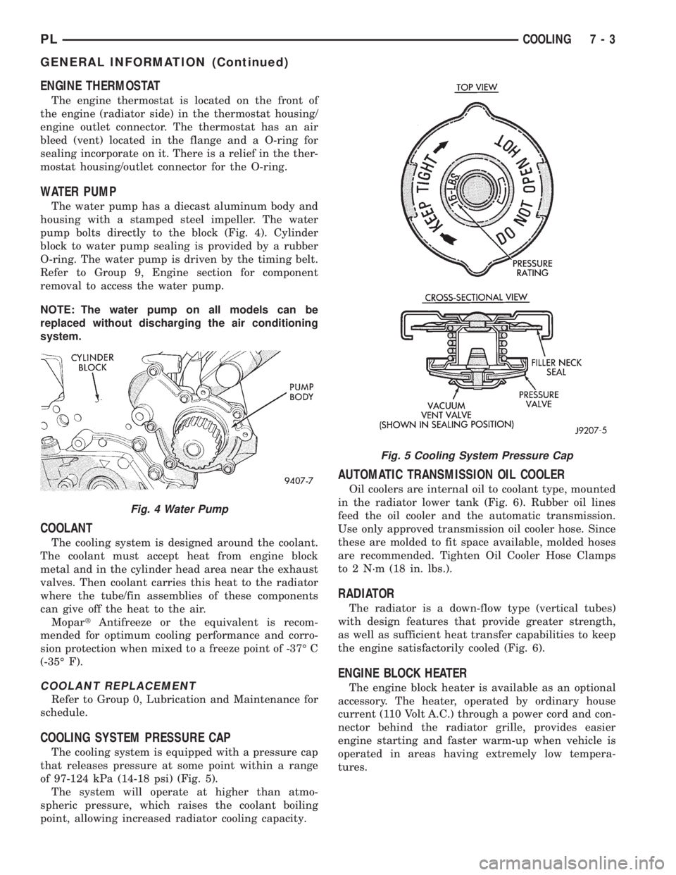
pump bolts directly to the block (Fig. 4). Cylinder
block to water pump sealing is provided by a rubber
O-ring. The water pump is driven by the timing belt.
Refer to Group 9, Engine section for component
removal to access the water pump.
NOTE: The water pump on all models can be
replaced without discharging the air conditioning
system.
COOLANT
The cooling system is designed around the coolant.
The coolant must accept heat from engine block
metal and in the cylinder head area near the exhaust
valves. Then coolant carries this heat to the radiator
where the tube/fin assemblies of these components
can give off the heat to the air.
MopartAntifreeze or the equivalent is recom-
mended for optimum cooling performance and corro-
sion protection when mixed to a freeze point of -37É C
(-35É F).
COOLANT REPLACEMENT
Refer to Group 0, Lubrication and Maintenance for
schedule.
COOLING SYSTEM PRESSURE CAP
The cooling system is equipped with a pressure cap
that releases pressure at some point within a range
of 97-124 kPa (14-18 psi) (Fig. 5).
The system will operate at higher than atmo-
spheric pressure, which raises the coolant boiling
point, allowing increased radiator cooling capacity.
AUTOMATIC TRANSMISSION OIL COOLER
Oil coolers are internal oil to coolant type, mounted
in the radiator lower tank (Fig. 6). Rubber oil lines
feed the oil cooler and the automatic transmission.
Use only approved transmission oil cooler hose. Since
these are molded to fit space available, molded hoses
are recommended. Tighten Oil Cooler Hose Clamps
to 2 N´m (18 in. lbs.).
RADIATOR
The radiator is a down-flow type (vertical tubes)
with design features that provide greater strength,
as well as sufficient heat transfer capabilities to keep
the engine satisfactorily cooled (Fig. 6).
ENGINE BLOCK HEATER
The engine block heater is available as an optional
accessory. The heater, operated by ordinary house
current (110 Volt A.C.) through a power cord and con-
nector behind the radiator grille, provides easier
engine starting and faster warm-up when vehicle is
operated in areas having extremely low tempera-
tures.
Fig. 4 Water Pump
Fig. 5 Cooling System Pressure Cap
PLCOOLING 7 - 3
GENERAL INFORMATION (Continued)
Page 209 of 1200
escapes to the atmosphere in the CRS tank and is
replaced with solid coolant on cool down.
TEMPERATURE GAUGE INDICATION
At idle the temperature gauge could rise slowly to
about 1/2 gauge travel. The fan will come on and the
gauge could drop to about 1/3 gauge travel, this is
normal.
SERVICE PROCEDURES
COOLANT LEVEL CHECKÐROUTINE
NOTE: Do not remove radiator cap for routine cool-
ant level inspections.
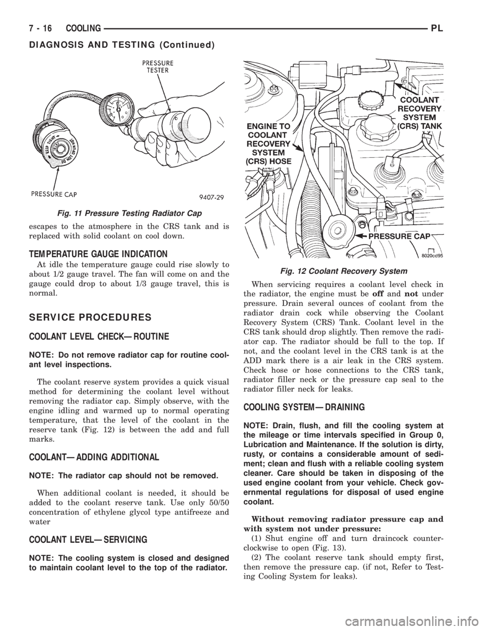
The coolant reserve system provides a quick visual
method for determining the coolant level without
removing the radiator cap. Simply observe, with the
engine idling and warmed up to normal operating
temperature, that the level of the coolant in the
reserve tank (Fig. 12) is between the add and full
marks.
COOLANTÐADDING ADDITIONAL
NOTE: The radiator cap should not be removed.
When additional coolant is needed, it should be
added to the coolant reserve tank. Use only 50/50
concentration of ethylene glycol type antifreeze and
water
COOLANT LEVELÐSERVICING
NOTE: The cooling system is closed and designed
to maintain coolant level to the top of the radiator.When servicing requires a coolant level check in
the radiator, the engine must beoffandnotunder
pressure. Drain several ounces of coolant from the
radiator drain cock while observing the Coolant
Recovery System (CRS) Tank. Coolant level in the
CRS tank should drop slightly. Then remove the radi-
ator cap. The radiator should be full to the top. If
not, and the coolant level in the CRS tank is at the
ADD mark there is a air leak in the CRS system.
Check hose or hose connections to the CRS tank,
radiator filler neck or the pressure cap seal to the
radiator filler neck for leaks.
COOLING SYSTEMÐDRAINING
NOTE: Drain, flush, and fill the cooling system at
the mileage or time intervals specified in Group 0,
Lubrication and Maintenance. If the solution is dirty,
rusty, or contains a considerable amount of sedi-
ment; clean and flush with a reliable cooling system
cleaner. Care should be taken in disposing of the
used engine coolant from your vehicle. Check gov-
ernmental regulations for disposal of used engine
coolant.
Without removing radiator pressure cap and
with system not under pressure:
(1) Shut engine off and turn draincock counter-
clockwise to open (Fig. 13).
(2) The coolant reserve tank should empty first,
then remove the pressure cap. (if not, Refer to Test-
ing Cooling System for leaks).
Fig. 11 Pressure Testing Radiator Cap
Fig. 12 Coolant Recovery System
7 - 16 COOLINGPL
DIAGNOSIS AND TESTING (Continued)
Page 218 of 1200
BATTERY
CONTENTS
page page
GENERAL INFORMATION
INTRODUCTION......................... 1
DESCRIPTION AND OPERATION
BATTERY IGNITION OFF DRAW (IOD)........ 1
CHARGING TIME REQUIRED............... 1
DIAGNOSIS AND TESTING
BATTERY BUILT-IN TEST INDICATOR........ 2
BATTERY IGNITION OFF DRAW (IOD)........ 3
BATTERY LOAD TEST..................... 5
BATTERY OPEN CIRCUIT VOLTAGE TEST..... 6
BATTERY TEMPERATURE SENSOR.......... 6
SERVICE PROCEDURES
BATTERY CHARGING..................... 6CHARGING COMPLETELY DISCHARGED
BATTERY............................. 7
VISUAL INSPECTION..................... 7
REMOVAL AND INSTALLATION
BATTERY TRAY.......................... 9
BATTERY............................... 8
FRESH AIR INLET TUBE REMOVAL.......... 9
SPECIFICATIONS
BATTERY SPECIFICATIONS............... 10
TORQUE.............................. 10
GENERAL INFORMATION
INTRODUCTION
The battery stores, stabilizes, and delivers electri-
cal current to operate various electrical systems in
the vehicle. The determination of whether a battery
is good or bad is made by its ability to accept a
charge. It also must supply high-amperage current
for a long enough period to be able to start the vehi-
cle. The capability of the battery to store electrical
current comes from a chemical reaction. This reac-
tion takes place between the sulfuric acid solution
(electrolyte) and the lead +/- plates in each cell of the
battery. As the battery discharges, the plates react
with the acid from the electrolyte. When the charging
system charges the battery, the water is converted to
sulfuric acid in the battery. The concentration of acid
in the electrolyte is measured as specific gravity
using a hydrometer. The original equipment (OE)
battery is equipped with a hydrometer (test indica-
tor) built into the battery cover. The specific gravity
indicates the battery's state-of-charge. The OE bat-
tery is sealed and water cannot be added.
The battery is vented to release gases that are cre-
ated when the battery is being charged and dis-
charged. The battery top, posts, and terminals should
be cleaned when other under hood maintenance is
performed.
When the electrolyte level is below the top of the
plates, Yellow/Clear in the test Indicator, the battery
must be replaced. The battery must be completely
charged, and the battery top, posts, and cable clampsmust be cleaned before diagnostic procedures are per-
formed.DESCRIPTION AND OPERATION
BATTERY IGNITION OFF DRAW (IOD)
A completely normal vehicle will have a small
amount of current drain on the battery with the key
out of the ignition. It can range from 4 to 10 milli-
amperes after all the modules time out. If a vehicle
will not be operated for approximately a 20 days, the
IOD fuse should be disconnected to minimize the
vehicle electrical drain on the battery. The IOD fuse
is located in the Power Distribution Center (PDC).
Refer to the PDC to locate the cover proper fuse.
CHARGING TIME REQUIRED
WARNING: NEVER EXCEED 20 AMPS WHEN
CHARGING A COLD -1ÉC (30ÉF) BATTERY. PER-
SONAL INJURY MAY RESULT.
The time required to charge a battery will vary
depending upon the following factors.
SIZE OF BATTERY
A completely discharged large heavy-duty battery
may require more recharging time than a completely
discharged small capacity battery. Refer to Battery
Charging Timetable for proper charging times.
PLBATTERY 8A - 1