1999 DODGE NEON clock
[x] Cancel search: clockPage 657 of 1200

Connector
Name/NumberColor Location Fig.
Passenger Door
Lock MotorGY At Motor 18
Right Front Side
Marker LampNAT At Lamp 5
Right Front
Wheel Speed
SensorGY RT Fender Side
Shield5
Right Headlamp BK At Lamp 5
Right Instrument
Panel SpeakerBK At Speaker N/S
Right Park/Turn
Signal LampBK At Lamp 5
Right Power
MirrorGY At Mirror 18
Right Rear Door
Lock MotorBK At Motor 18
Right Rear
SpeakerBK At Speaker 20
Right Rear
Wheel Speed
SensorGY RT Rear Frame
RailN/S
Right Tail/Stop
Turn Signal
LampBK At Lamp 24
Seat Belt Switch BK LT B-Pillar N/S
Right Headlamp
Leveling MotorBK Rear of Right
HeadlampN/S
Solid State Fan
RelayBK Behind Left
Headlamp7
Stop Lamp
SwitchGY Top of Brake
Pedal2
Sunroof Slide
SwitchBL Front of
Windshield
Header11
Connector
Name/NumberColor Location Fig.
Sunroof Vent
SwitchYL Front of
Windshield
Header11
Throttle Position
SensorNAT On Throttle
Body9
Torque Converter
Clutch SolenoidBK Front of
Transmission4
Trunk Lamp BK At Lamp 21
Turn Signal/
Hazard SwitchBK Rear of Switch 12
Underhood Lamp BK Right Rear
Cowel PanelN/S
Upstream
Heated Oxygen
SensorGY Rear of Engine 8
Vapor Canister
Leak DetectorBK RT Front Fender 5
Vehicle Speed
Control ServoBK Side of Battery
TrayN/S
Vehicle Speed
Control SwitchNAT Rear of
ClockspringN/S
Vehicle Speed
SensorBK Rear of
Transmisison4
Wipe/Wash
SwitchNAT Rear of Switch 12
WIndshield
Washer Pump
MotorBK Bottom of
Reservior7
Wiper Motor BK Center of Cowl
Panel10
8W - 90 - 4 8W - 90 CONNECTOR/GROUND LOCATIONSPL
DESCRIPTION AND OPERATION (Continued)
Page 676 of 1200
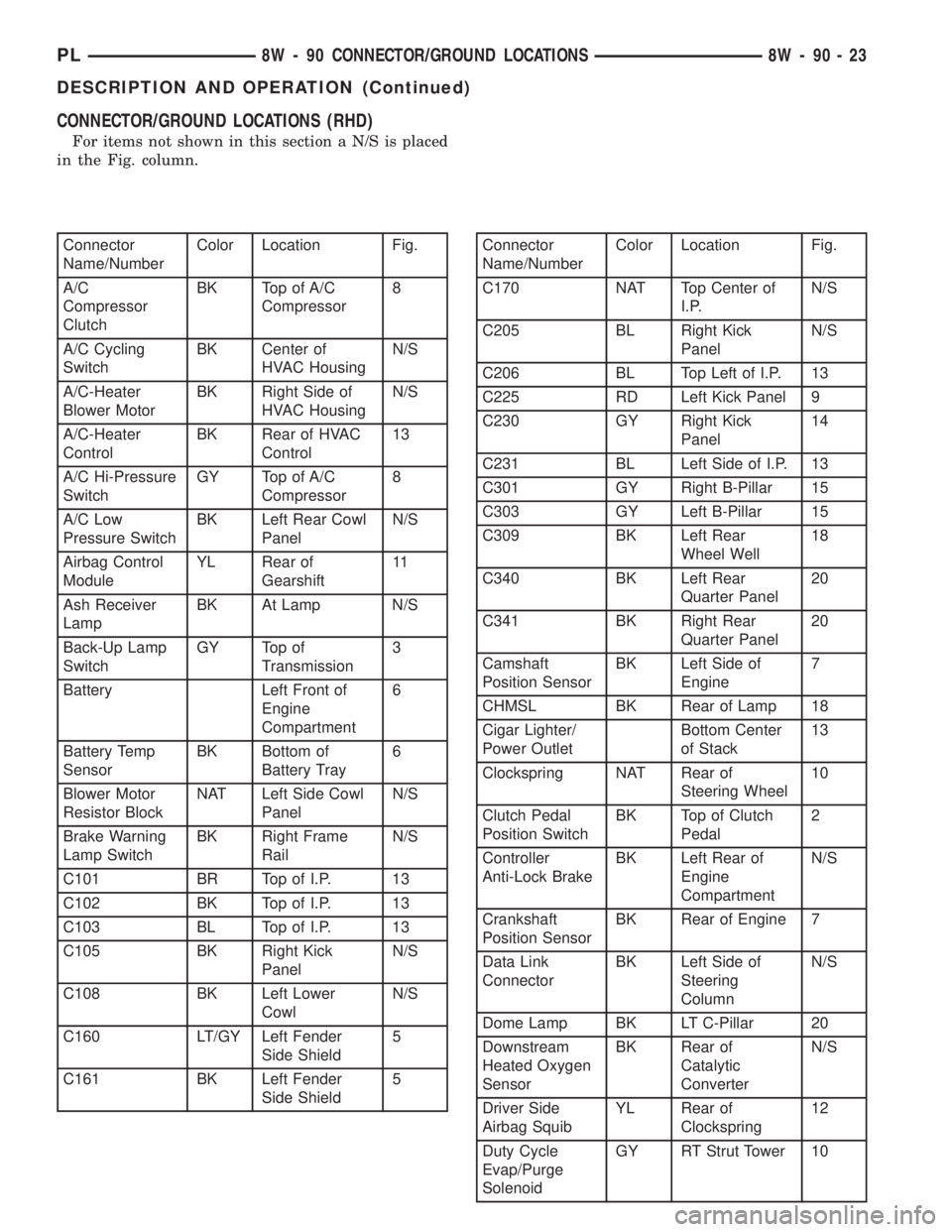
CONNECTOR/GROUND LOCATIONS (RHD)
For items not shown in this section a N/S is placed
in the Fig. column.
Connector
Name/NumberColor Location Fig.
A/C
Compressor
ClutchBK Top of A/C
Compressor8
A/C Cycling
SwitchBK Center of
HVAC HousingN/S
A/C-Heater
Blower MotorBK Right Side of
HVAC HousingN/S
A/C-Heater
ControlBK Rear of HVAC
Control13
A/C Hi-Pressure
SwitchGY Top of A/C
Compressor8
A/C Low
Pressure SwitchBK Left Rear Cowl
PanelN/S
Airbag Control
ModuleYL Rear of
Gearshift11
Ash Receiver
LampBK At Lamp N/S
Back-Up Lamp
SwitchGY Top of
Transmission3
Battery Left Front of
Engine
Compartment6
Battery Temp
SensorBK Bottom of
Battery Tray6
Blower Motor
Resistor BlockNAT Left Side Cowl
PanelN/S
Brake Warning
Lamp SwitchBK Right Frame
RailN/S
C101 BR Top of I.P. 13
C102 BK Top of I.P. 13
C103 BL Top of I.P. 13
C105 BK Right Kick
PanelN/S
C108 BK Left Lower
CowlN/S
C160 LT/GY Left Fender
Side Shield5
C161 BK Left Fender
Side Shield5Connector
Name/NumberColor Location Fig.
C170 NAT Top Center of
I.P.N/S
C205 BL Right Kick
PanelN/S
C206 BL Top Left of I.P. 13
C225 RD Left Kick Panel 9
C230 GY Right Kick
Panel14
C231 BL Left Side of I.P. 13
C301 GY Right B-Pillar 15
C303 GY Left B-Pillar 15
C309 BK Left Rear
Wheel Well18
C340 BK Left Rear
Quarter Panel20
C341 BK Right Rear
Quarter Panel20
Camshaft
Position SensorBK Left Side of
Engine7
CHMSL BK Rear of Lamp 18
Cigar Lighter/
Power OutletBottom Center
of Stack13
Clockspring NAT Rear of
Steering Wheel10
Clutch Pedal
Position SwitchBK Top of Clutch
Pedal2
Controller
Anti-Lock BrakeBK Left Rear of
Engine
CompartmentN/S
Crankshaft
Position SensorBK Rear of Engine 7
Data Link
ConnectorBK Left Side of
Steering
ColumnN/S
Dome Lamp BK LT C-Pillar 20
Downstream
Heated Oxygen
SensorBK Rear of
Catalytic
ConverterN/S
Driver Side
Airbag SquibYL Rear of
Clockspring12
Duty Cycle
Evap/Purge
SolenoidGY RT Strut Tower 10
PL8W - 90 CONNECTOR/GROUND LOCATIONS 8W - 90 - 23
DESCRIPTION AND OPERATION (Continued)
Page 679 of 1200
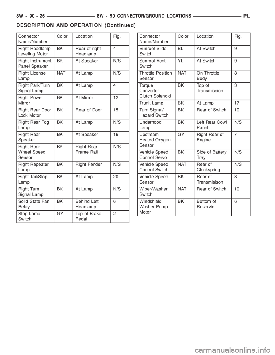
Connector
Name/NumberColor Location Fig.
Right Headlamp
Leveling MotorBK Rear of right
Headlamp4
Right Instrument
Panel SpeakerBK At Speaker N/S
Right License
LampNAT At Lamp N/S
Right Park/Turn
Signal LampBK At Lamp 4
Right Power
MirrorBK At Mirror 12
Right Rear Door
Lock MotorBK Rear of Door 15
Right Rear Fog
LampBK At Lamp N/S
Right Rear
SpeakerBK At Speaker 16
Right Rear
Wheel Speed
SensorBK Right Rear
Frame RailN/S
Right Repeater
LampBK Right Fender N/S
Right Tail/Stop
LampBK At Lamp 20
Right Turn
Signal LampBK At Lamp N/S
Solid State Fan
RelayBK Behind Left
Headlamp6
Stop Lamp
SwitchGY Top of Brake
Pedal2Connector
Name/NumberColor Location Fig.
Sunroof Slide
SwitchBL At Switch 9
Sunroof Vent
SwitchYL At Switch 9
Throttle Position
SensorNAT On Throttle
Body8
Torque
Converter
Clutch SolenoidBK Top of
Transmission3
Trunk Lamp BK At Lamp 17
Turn Signal/
Hazard SwitchBK Rear of Switch 10
Underhood
LampBK Left Rear Cowl
PanelN/S
Upstream
Heated Oxygen
SensorGY Right Rear of
Engine7
Vehicle Speed
Control ServoBK Side of Battery
TrayN/S
Vehicle Speed
Control SwitchNAT Rear of
ClockspringN/S
Vehicle Speed
SensorBK Rear of
Transmisison3
Wiper/Washer
SwitchNAT Rear of Switch 10
WIndshield
Washer Pump
MotorBK Bottom of
Reservior6
8W - 90 - 26 8W - 90 CONNECTOR/GROUND LOCATIONSPL
DESCRIPTION AND OPERATION (Continued)
Page 747 of 1200
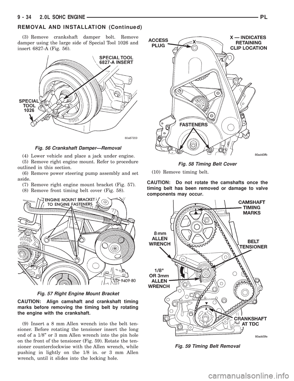
(3) Remove crankshaft damper bolt. Remove
damper using the large side of Special Tool 1026 and
insert 6827-A (Fig. 56).
(4) Lower vehicle and place a jack under engine.
(5) Remove right engine mount. Refer to procedure
outlined in this section.
(6) Remove power steering pump assembly and set
aside.
(7) Remove right engine mount bracket (Fig. 57).
(8) Remove front timing belt cover (Fig. 58).
CAUTION: Align camshaft and crankshaft timing
marks before removing the timing belt by rotating
the engine with the crankshaft.
(9) Inserta8mmAllen wrench into the belt ten-
sioner. Before rotating the tensioner insert the long
end of a 1/8º or 3 mm Allen wrench into the pin hole
on the front of the tensioner (Fig. 59). Rotate the ten-
sioner counterclockwise with the Allen wrench, while
pushing in lightly on the 1/8 in. or 3 mm Allen
wrench, until it slides into the locking hole.(10) Remove timing belt.
CAUTION: Do not rotate the camshafts once the
timing belt has been removed or damage to valve
components may occur.
Fig. 56 Crankshaft DamperÐRemoval
Fig. 57 Right Engine Mount Bracket
Fig. 58 Timing Belt Cover
Fig. 59 Timing Belt Removal
9 - 34 2.0L SOHC ENGINEPL
REMOVAL AND INSTALLATION (Continued)
Page 755 of 1200
(11) Install oil pump. If crankshaft end play is to
be checked refer to service procedures in this section.
(12) Install crankshaft sprocket.
(13) Install oil filter adapter and filter.
(14) Install oil pan and structural collar. Refer to
procedures outlined in the section.
(15) Perform camshaft and crankshaft timing
relearn procedure as follows:
²Connect the DRB scan tool to the data link
(diagnostic) connector. This connector is located in
the passenger compartment; at the lower edge of
instrument panel; near the steering column.
²Turn the ignition switch on and access the ªmis-
cellaneousº screen.
²Select ªre-learn cam/crankº option and follow
directions on DRB screen.
OIL FILTER ADAPTER
REMOVE AND INSTALL
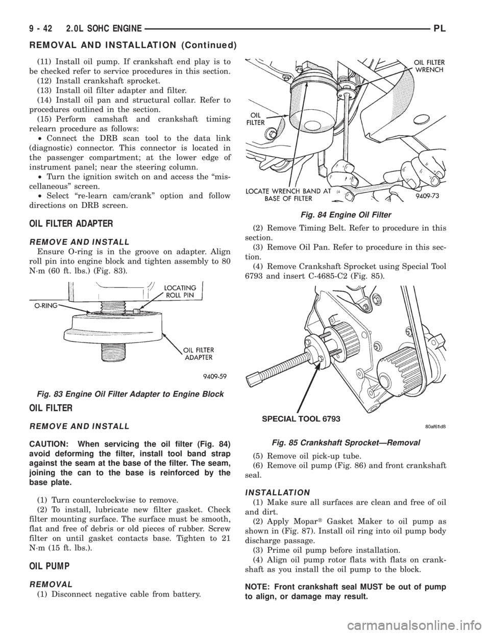
Ensure O-ring is in the groove on adapter. Align
roll pin into engine block and tighten assembly to 80
N´m (60 ft. lbs.) (Fig. 83).
OIL FILTER
REMOVE AND INSTALL
CAUTION: When servicing the oil filter (Fig. 84)
avoid deforming the filter, install tool band strap
against the seam at the base of the filter. The seam,
joining the can to the base is reinforced by the
base plate.
(1) Turn counterclockwise to remove.
(2) To install, lubricate new filter gasket. Check
filter mounting surface. The surface must be smooth,
flat and free of debris or old pieces of rubber. Screw
filter on until gasket contacts base. Tighten to 21
N´m (15 ft. lbs.).
OIL PUMP
REMOVAL
(1) Disconnect negative cable from battery.(2) Remove Timing Belt. Refer to procedure in this
section.
(3) Remove Oil Pan. Refer to procedure in this sec-
tion.
(4) Remove Crankshaft Sprocket using Special Tool
6793 and insert C-4685-C2 (Fig. 85).
(5) Remove oil pick-up tube.
(6) Remove oil pump (Fig. 86) and front crankshaft
seal.
INSTALLATION
(1) Make sure all surfaces are clean and free of oil
and dirt.
(2) Apply MopartGasket Maker to oil pump as
shown in (Fig. 87). Install oil ring into oil pump body
discharge passage.
(3) Prime oil pump before installation.
(4) Align oil pump rotor flats with flats on crank-
shaft as you install the oil pump to the block.
NOTE: Front crankshaft seal MUST be out of pump
to align, or damage may result.
Fig. 83 Engine Oil Filter Adapter to Engine Block
Fig. 84 Engine Oil Filter
Fig. 85 Crankshaft SprocketÐRemoval
9 - 42 2.0L SOHC ENGINEPL
REMOVAL AND INSTALLATION (Continued)
Page 789 of 1200
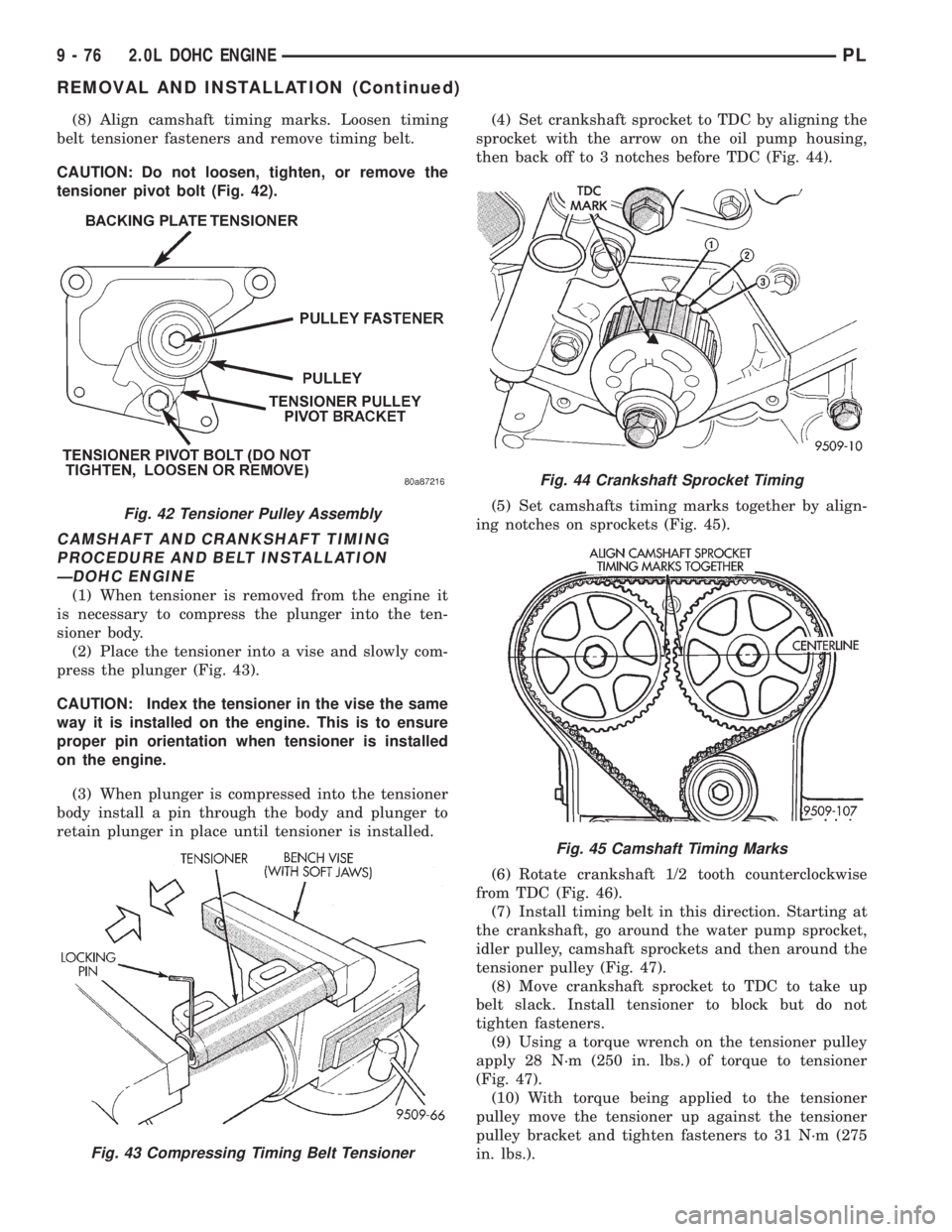
(8) Align camshaft timing marks. Loosen timing
belt tensioner fasteners and remove timing belt.
CAUTION: Do not loosen, tighten, or remove the
tensioner pivot bolt (Fig. 42).
CAMSHAFT AND CRANKSHAFT TIMING
PROCEDURE AND BELT INSTALLATION
ÐDOHC ENGINE
(1) When tensioner is removed from the engine it
is necessary to compress the plunger into the ten-
sioner body.
(2) Place the tensioner into a vise and slowly com-
press the plunger (Fig. 43).
CAUTION: Index the tensioner in the vise the same
way it is installed on the engine. This is to ensure
proper pin orientation when tensioner is installed
on the engine.
(3) When plunger is compressed into the tensioner
body install a pin through the body and plunger to
retain plunger in place until tensioner is installed.(4) Set crankshaft sprocket to TDC by aligning the
sprocket with the arrow on the oil pump housing,
then back off to 3 notches before TDC (Fig. 44).
(5) Set camshafts timing marks together by align-
ing notches on sprockets (Fig. 45).
(6) Rotate crankshaft 1/2 tooth counterclockwise
from TDC (Fig. 46).
(7) Install timing belt in this direction. Starting at
the crankshaft, go around the water pump sprocket,
idler pulley, camshaft sprockets and then around the
tensioner pulley (Fig. 47).
(8) Move crankshaft sprocket to TDC to take up
belt slack. Install tensioner to block but do not
tighten fasteners.
(9) Using a torque wrench on the tensioner pulley
apply 28 N´m (250 in. lbs.) of torque to tensioner
(Fig. 47).
(10) With torque being applied to the tensioner
pulley move the tensioner up against the tensioner
pulley bracket and tighten fasteners to 31 N´m (275
in. lbs.).
Fig. 42 Tensioner Pulley Assembly
Fig. 43 Compressing Timing Belt Tensioner
Fig. 44 Crankshaft Sprocket Timing
Fig. 45 Camshaft Timing Marks
9 - 76 2.0L DOHC ENGINEPL
REMOVAL AND INSTALLATION (Continued)
Page 792 of 1200
CAUTION: Align camshaft and crankshaft timing
marks before removing the timing belt by rotating
the engine with the crankshaft. Do not rotate the
camshaft once the timing belt has been removed as
damage to valve components may occur.
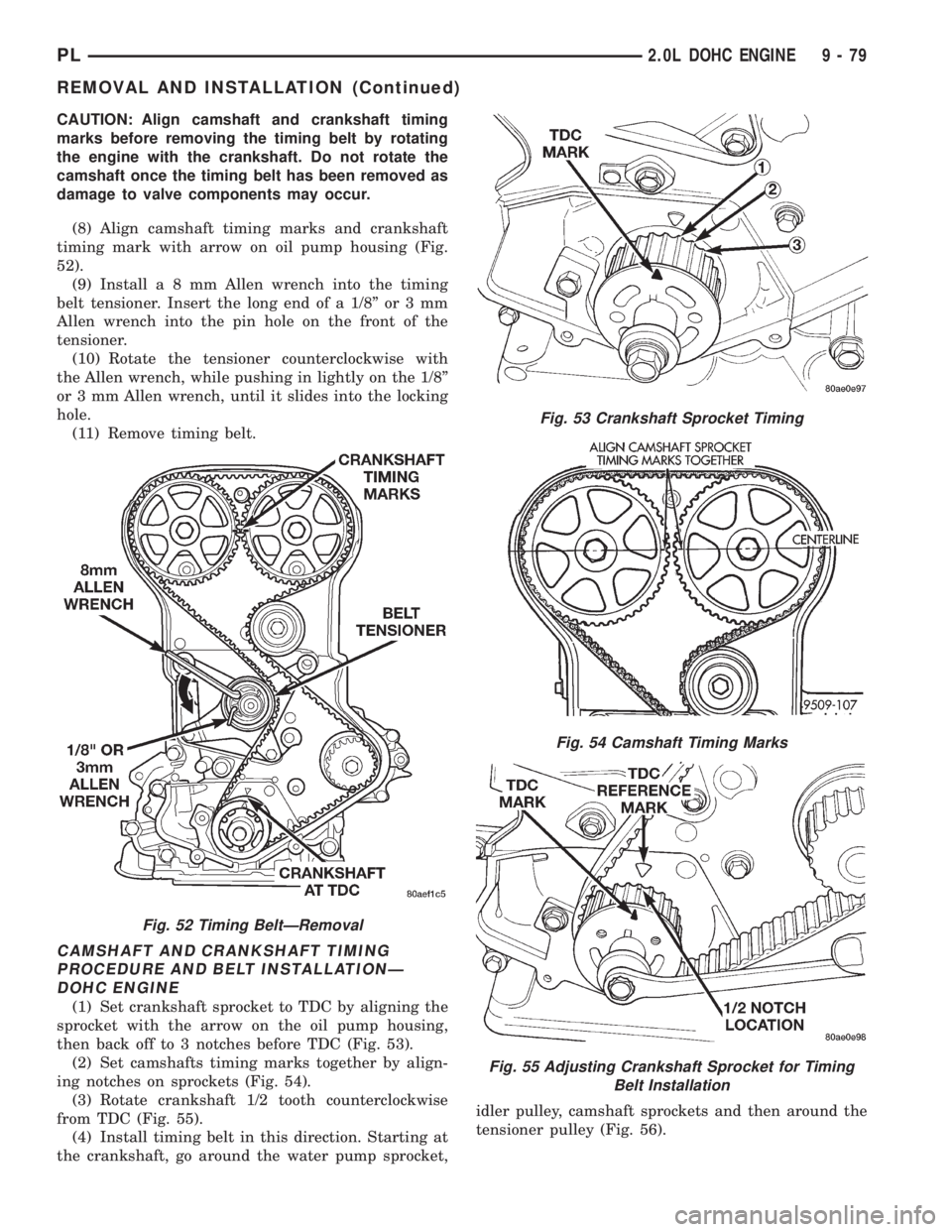
(8) Align camshaft timing marks and crankshaft
timing mark with arrow on oil pump housing (Fig.
52).
(9) Installa8mmAllen wrench into the timing
belt tensioner. Insert the long end of a 1/8º or 3 mm
Allen wrench into the pin hole on the front of the
tensioner.
(10) Rotate the tensioner counterclockwise with
the Allen wrench, while pushing in lightly on the 1/8º
or 3 mm Allen wrench, until it slides into the locking
hole.
(11) Remove timing belt.
CAMSHAFT AND CRANKSHAFT TIMING
PROCEDURE AND BELT INSTALLATIONÐ
DOHC ENGINE
(1) Set crankshaft sprocket to TDC by aligning the
sprocket with the arrow on the oil pump housing,
then back off to 3 notches before TDC (Fig. 53).
(2) Set camshafts timing marks together by align-
ing notches on sprockets (Fig. 54).
(3) Rotate crankshaft 1/2 tooth counterclockwise
from TDC (Fig. 55).
(4) Install timing belt in this direction. Starting at
the crankshaft, go around the water pump sprocket,idler pulley, camshaft sprockets and then around the
tensioner pulley (Fig. 56).
Fig. 52 Timing BeltÐRemoval
Fig. 53 Crankshaft Sprocket Timing
Fig. 54 Camshaft Timing Marks
Fig. 55 Adjusting Crankshaft Sprocket for Timing
Belt Installation
PL2.0L DOHC ENGINE 9 - 79
REMOVAL AND INSTALLATION (Continued)
Page 800 of 1200
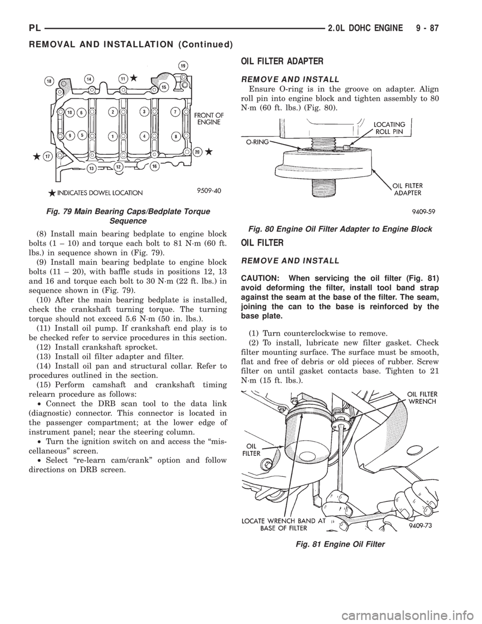
(8) Install main bearing bedplate to engine block
bolts (1 ± 10) and torque each bolt to 81 N´m (60 ft.
lbs.) in sequence shown in (Fig. 79).
(9) Install main bearing bedplate to engine block
bolts (11 ± 20), with baffle studs in positions 12, 13
and 16 and torque each bolt to 30 N´m (22 ft. lbs.) in
sequence shown in (Fig. 79).
(10) After the main bearing bedplate is installed,
check the crankshaft turning torque. The turning
torque should not exceed 5.6 N´m (50 in. lbs.).
(11) Install oil pump. If crankshaft end play is to
be checked refer to service procedures in this section.
(12) Install crankshaft sprocket.
(13) Install oil filter adapter and filter.
(14) Install oil pan and structural collar. Refer to
procedures outlined in the section.
(15) Perform camshaft and crankshaft timing
relearn procedure as follows:
²Connect the DRB scan tool to the data link
(diagnostic) connector. This connector is located in
the passenger compartment; at the lower edge of
instrument panel; near the steering column.
²Turn the ignition switch on and access the ªmis-
cellaneousº screen.
²Select ªre-learn cam/crankº option and follow
directions on DRB screen.
OIL FILTER ADAPTER
REMOVE AND INSTALL
Ensure O-ring is in the groove on adapter. Align
roll pin into engine block and tighten assembly to 80
N´m (60 ft. lbs.) (Fig. 80).
OIL FILTER
REMOVE AND INSTALL
CAUTION: When servicing the oil filter (Fig. 81)
avoid deforming the filter, install tool band strap
against the seam at the base of the filter. The seam,
joining the can to the base is reinforced by the
base plate.
(1) Turn counterclockwise to remove.
(2) To install, lubricate new filter gasket. Check
filter mounting surface. The surface must be smooth,
flat and free of debris or old pieces of rubber. Screw
filter on until gasket contacts base. Tighten to 21
N´m (15 ft. lbs.).
Fig. 79 Main Bearing Caps/Bedplate Torque
Sequence
Fig. 80 Engine Oil Filter Adapter to Engine Block
Fig. 81 Engine Oil Filter
PL2.0L DOHC ENGINE 9 - 87
REMOVAL AND INSTALLATION (Continued)