1999 DODGE NEON ECO mode
[x] Cancel search: ECO modePage 1148 of 1200
This A/C system does not have or use a sight glass to
check or charge the system.
WARNING: REVIEW SAFETY PRECAUTIONS AND
WARNINGS IN THIS GROUP BEFORE CHARGING
THE REFRIGERANT SYSTEM.
AVOID BREATHING A/C REFRIGERANT AND
LUBRICANT VAPOR OR MIST. EXPOSURE MAY
IRRITATE EYES, NOSE AND THROAT. USE ONLY
APPROVED SERVICE EQUIPMENT MEETING SAE
REQUIREMENTS TO DISCHARGE R-134a SYSTEM.
IF ACCIDENTAL SYSTEM DISCHARGE OCCURS,
VENTILATE WORK AREA BEFORE RESUMING SER-
VICE.
R-134a SERVICE EQUIPMENT OR VEHICLE A/C
SYSTEM SHOULD NOT BE PRESSURE TESTED OR
LEAK TESTED WITH COMPRESSED AIR. MIXTURE
OF AIR and R-134a CAN BE COMBUSTIBLE AT ELE-
VATED PRESSURES. THESE MIXTURES ARE
POTENTIALLY DANGEROUS AND MAY RESULT IN
FIRE OR EXPLOSION CAUSING INJURY OR PROP-
ERTY DAMAGE.
CAUTION: Do not overcharge refrigerant system,
as excessive compressor head pressure can cause
noise and system failure.
After the system has been tested for leaks and
evacuated, a refrigerant (R-134a) charge can be
injected into the system.
NOTE: When connecting the service equipment
coupling to the line fitting, verify that the valve of
the coupling is fully closed. This will reduce the
amount of effort required to make the connection.
(1) If using a separate vacuum pump close all
valves before disconnecting pump. Connect manifold
gauge set to the A/C service ports (Fig. 14).
NOTE: The air conditioning system in this vehicle
holds 784 grams (28 oz. or 1.57 lbs.) of R-134a
refrigerant.
(2) Measure refrigerant (refer to capacities). Refer
to the instructions provided with the equipment
being used.
(3) Verify engine is shut off. Open the suction and
discharge valves. Open the charge valve to allow the
refrigerant to flow into the system. When the trans-
fer of refrigerant has stopped, close the suction and
discharge valve.
(4) If all of the charge did not transfer from the
dispensing device, put vehicle controls into the fol-
lowing mode:
²Automatic transaxle in park or manual tran-
saxle in neutral²Engine idling at 700 rpm
²A/C control set in 100 percent outside air
²Panel mode
²Blower motor ON high speed
²Vehicle windows closed
If the A/C compressor does not engage, test the
compressor clutch control circuit and correct any fail-
ure. Refer to Group 8W, Wiring Diagrams.
(5) Open the suction valve to allow the remaining
refrigerant to transfer to the system.
WARNING: TAKE CARE NOT TO OPEN THE DIS-
CHARGE (HIGH-PRESSURE) VALVE AT THIS TIME.
(6) Close all valves and test the A/C system perfor-
mance.
(7) Disconnect the charging station or manifold
gauge set. Install the service port caps.
EVACUATING REFRIGERANT SYSTEM
NOTE: Special effort must be used to prevent mois-
ture from entering the A/C system oil. Moisture in
the oil is very difficult to remove and will cause a
reliability problem with the compressor.
If a compressor designed to use R-134a refrigerant
is left open to the atmosphere for an extended period
of time. It is recommended that the refrigerant oil be
drained and replaced with new oil or a new compres-
sor be used. This will eliminate the possibility of con-
taminating the refrigerant system.
If the refrigerant system has been open to the
atmosphere, it must be evacuated before the system
can be filled. Moisture and air mixed with the refrig-
erant will raise the compressor head pressure above
acceptable operating levels. This will reduce the per-
formance of the air conditioner and damage the com-
pressor. Moisture will boil at near room temperature
when exposed to vacuum. To evacuate the refrigerant
system:
NOTE: When connecting the service equipment
coupling to the line fitting, verify that the valve of
the coupling is fully closed. This will reduce the
amount of effort required to make the connection.
(1) Connect a suitable charging station, refrigerant
recovery machine, and a manifold gauge set with
vacuum pump (Fig. 15).
(2) Open the suction and discharge valves and
start the vacuum pump. The vacuum pump should
run a minimum of 45 minutes prior to charge to
eliminate all moisture in system. When the suction
gauge reads -88 kPa (- 26 in. Hg) vacuum or greater
for 45 minutes, close all valves and turn off vacuum
pump. If the system fails to reach specified vacuum,
PLHEATING AND AIR CONDITIONING 24 - 15
SERVICE PROCEDURES (Continued)
Page 1154 of 1200
(4) Install pulley assembly retaining snap ring
(bevel side outward) with Snap Ring Pliers. Press the
snap ring to make sure it is properly seated in the
groove.
(5) If the original front plate assembly and pulley
assembly are to be reused, the old shim(s) can be
used. If not, place a trial stack of shims, 2.54 mm
(0.10 in.) thick, on the shaft against the shoulder.
(6) Install front plate assembly onto shaft.
(7) If installing a new front plate and/or pulley
assembly, the gap between front plate and pulley face
must be checked. Use the following procedure:
(a) Attach a dial indicator to front plate so that
movement of the plate can be measured.
(b) With the dial indicator zeroed on the front
plate, energize the clutch and record the amount of
movement.
(c) The readings should be 0.35 to 0.65 mm
(0.014 to 0.026 in.). If proper reading is not
obtained, add or subtract shims until desired read-
ing is obtained.
(8) Install compressor shaft bolt. Tighten to 17.5
62 N´m (155620 in. lbs.) torque.
NOTE: Shims may compress after tightening shaft
nut. Check air gap in four or more places to verify if
air gap is still correct. Spin pulley for final check.
CLUTCH BREAK-IN
After new clutch installation, cycle the A/C clutch
20 times (5 seconds on and 5 seconds off). During
this procedure, set the system to the A/C mode,
engine rpm at 1500 - 2000, and high blower speed.
This procedure (burnishing) will seat the opposing
friction surfaces and provide a higher clutch torque
capability.
CONDENSATION DRAIN TUBE
REMOVAL
(1) Raise vehicle.
(2) Locate rubber drain tube on right side of dash
panel (Fig. 25).
(3) Squeeze clamp and remove drain tube.
INSTALLATION
To install, reverse the preceding operation. Check
the drain tube nipple on the heater-A/C housing for
any obstructions.
CONDENSER
The condenser is located in front of the engine
radiator. It has no serviceable parts. If damaged or
leaking, the condenser assembly must be replaced.WARNING: THE REFRIGERANT MUST BE
REMOVED FROM THE SYSTEM BEFORE REMOV-
ING THE CONDENSER.
REMOVAL
(1) Using a R-134a refrigerant recovery machine,
remove the refrigerant from the A/C system.
(2) Remove battery support strut.
(3) Remove refrigerant lines from condenser.
(4) Remove upper radiator mounts.
(5) Remove condenser to radiator mounting
screws.
(6) Tilt radiator back and remove condenser.
INSTALLATION
For installation, reverse the above procedures.
DISCHARGE LINE
WARNING: THE REFRIGERANT SYSTEM MUST BE
RECOVERED BEFORE SERVICING ANY PART OF
THE REFRIGERANT SYSTEM.
REMOVAL
(1) Using a R-134a refrigerant recovery machine,
remove the refrigerant from A/C system.
(2) From the top side of the vehicle, remove line at
compressor (Fig. 26).
(3) From the bottom side of the vehicle, remove
line at condenser.
INSTALLATION
For installation, reverse the above procedures.
EVAPORATOR
This vehicle uses an aluminum plate and fin style
evaporator. It is located in the Evaporator/Blower
module.
Fig. 25 Condensate Water Drain Tube ± Typical
PLHEATING AND AIR CONDITIONING 24 - 21
REMOVAL AND INSTALLATION (Continued)
Page 1158 of 1200
LIQUID LINE
WARNING: THE REFRIGERATION SYSTEM MUST
BE COMPLETELY EMPTY BEFORE PROCEEDING
WITH THIS OPERATION.
REMOVAL
(1) Using a R-134a refrigerant recovery machine,
remove the refrigerant from A/C system.
(2) Disconnect liquid line at drier.
(3) Disconnect liquid line at condenser.
INSTALLATION
For installation, reverse the above procedures.
LOW PRESSURE CUT OFF SWITCH
WARNING: THE REFRIGERATION SYSTEM MUST
BE COMPLETELY RECOVERED BEFORE PRO-
CEEDING WITH THIS OPERATION. REFER TO
REFRIGERANT RECOVERY SECTION.
REMOVAL
(1) Disconnect the boot like wire connector at the
cut off switch.
(2) Using a sender unit removal socket, remove the
switch from the expansion valve (Fig. 34).
INSTALLATION
NOTE: Verify the O-ring condition on the replace-
ment switch.
For installation, reverse the above procedures.
Evacuate and charge the system.
MODE CONTROL CABLE
The Mode Control Cable can be removed and
installed without having to remove the instrument
panel from the vehicle.
REMOVAL
(1) Remove instrument panel upper cowl panel.
(2) Remove right side upper instrument panel
bezel (Fig. 35).
(3) Remove center vent duct (Fig. 36).
(4) Remove upper defrost duct (Fig. 37).
(5) Remove inner defrost duct (Fig. 38).
(6) Disconnect cable at heater unit.
(7) Disconnect cable at control panel.
(8) Remove cable from vehicle.
INSTALLATION
For installation, reverse the above procedures,
adjust cable and test. Refer to Mode Control Cable
Adjustment at the end of this section.
Fig. 34 Low Pressure Cut-Off Switch and Expansion
Valve ± Typical
Fig. 35 Bezel Removal
Fig. 36 Instrument Panel Center Vent
PLHEATING AND AIR CONDITIONING 24 - 25
REMOVAL AND INSTALLATION (Continued)
Page 1161 of 1200
(3) Using a refrigerant recovery machine, remove
the refrigerant from the A/C system, if equipped.
(4) Remove suction line at expansion valve. Place a
piece of tape over open refrigerant line to prevent
moisture and/or dirt from entering the line.
(5) Remove expansion valve from evaporator. Place
a piece of tape over open evaporator fitting to pre-
vent moisture and/or dirt from entering the evapora-
tor.
(6) Remove rubber drain tube extension from con-
densation drain tube.
(7) Remove three retaining nuts located in the
engine compartment, on the dash panel (Fig. 41).
(8) Remove the right side retaining screw (Fig. 42).
(9) Remove remaining nut located on dash panel
stud.
(10) Disconnect the blue five way connector from
the plenum. Module wiring harness must be removed
with module.
(11) Remove assembly from the vehicle.
INSTALLATION
For installation, reverse the above procedures.
DISASSEMBLY AND ASSEMBLY
AIR DISTRIBUTION MODULE ± RECONDITION
Use this procedure if any or all of the following
items require service:
²Heater core
²Temperature door
²Mode door
²Heat/Defrost door
²Assembly housing
The unit housing must be removed from the vehi-
cle before beginning with this procedure. Refer to
Unit Housing in this section for removal procedure.
DISASSEMBLE
For RHD vehicles, the Unit Housing does not sep-
arate. It is a one piece unit and must be replaced as
a whole.
(1) Remove the clips and screws that hold the Air
Distribution Module to the Evaporator/Blower Mod-
ule. Then separate the two units (Fig. 43).
(2) Remove the panel opening foam seal, demister
opening foam seal, and heater core tube foam seals
from unit.
(3) Remove the retaining clips and screws that
hold the upper and lower housings together (Fig. 44).
(4) Place the unit in the upside down position.
Then separate the two halves of the module (Fig. 45).
(5) Lift the heater core out of the case (Fig. 46).
(6) Press tab in at base of temperature door and
release door from lever (Fig. 47). Then remove the
door.
Fig. 41 Dash Panel Studs
Fig. 42 Retaining Screws
Fig. 43 Air Distribution and Evaporator/Blower
Module Separation
24 - 28 HEATING AND AIR CONDITIONINGPL
REMOVAL AND INSTALLATION (Continued)
Page 1165 of 1200
cranking. Whenever the Powertrain Control Module
(PCM) sets a Diagnostic Trouble Code (DTC) that
affects vehicle emissions, it illuminates the MIL. If a
problem is detected, the PCM sends a message over
the CCD Bus to the instrument cluster to illuminate
the lamp. The PCM illuminates the MIL only for
DTC's that affect vehicle emissions. The MIL stays
on continuously when the PCM has entered a
Limp-In mode or identified a failed emission compo-
nent or system. The MIL remains on until the DTC
is erased. Refer to the Diagnostic Trouble Code
charts in this group for emission related codes.
Also, the MIL either flashes or illuminates contin-
uously when the PCM detects active engine misfire.
Refer to Misfire Monitoring in this section.
Additionally, the PCM may reset (turn off) the MIL
when one of the following occur:
²PCM does not detect the malfunction for 3 con-
secutive trips (except misfire and fuel system moni-
tors).
²PCM does not detect a malfunction while per-
forming three successive engine misfire or fuel sys-
tem tests. The PCM performs these tests while the
engine is operating within6375 RPM of and within
10 % of the load of the operating condition at which
the malfunction was first detected.
STATE DISPLAY TEST MODE
The switch inputs to the Powertrain Control Mod-
ule (PCM) have two recognized states; HIGH and
LOW. For this reason, the PCM cannot recognize the
difference between a selected switch position versus
an open circuit, a short circuit, or a defective switch.
If the State Display screen shows the change from
HIGH to LOW or LOW to HIGH, assume the entire
switch circuit to the PCM functions properly. From
the state display screen, access either State Display
Inputs and Outputs or State Display Sensors.
CIRCUIT ACTUATION TEST MODE
The Circuit Actuation Test Mode checks for proper
operation of output circuits or devices the Powertrain
Control Module (PCM) may not internally recognize.
The PCM attempts to activate these outputs and
allow an observer to verify proper operation. Most of
the tests provide an audible or visual indication of
device operation (click of relay contacts, fuel spray,
etc.). Except for intermittent conditions, if a device
functions properly during testing, assume the device,
its associated wiring, and driver circuit work cor-
rectly.
DIAGNOSTIC TROUBLE CODES
A Diagnostic Trouble Code (DTC) indicates the
PCM has recognized an abnormal condition in the
system.
²The preferred and most accurate method of
retrieving a DTC is by using the DRB scan tool. The
scan tool supplies detailed diagnostic information
which can be used to more accurately diagnose
causes for a DTC.
Remember that DTC's are the results of a sys-
tem or circuit failure, but do not directly iden-
tify the failed component or components.
NOTE: For a list of DTC's, refer to the charts in this
section.
BULB CHECK
Each time the ignition key is turned to the ON
position, the malfunction indicator (check engine)
lamp on the instrument panel should illuminate for
approximately 2 seconds then go out. This is done for
a bulb check.
OBTAINING DTC'S USING DRB SCAN TOOL
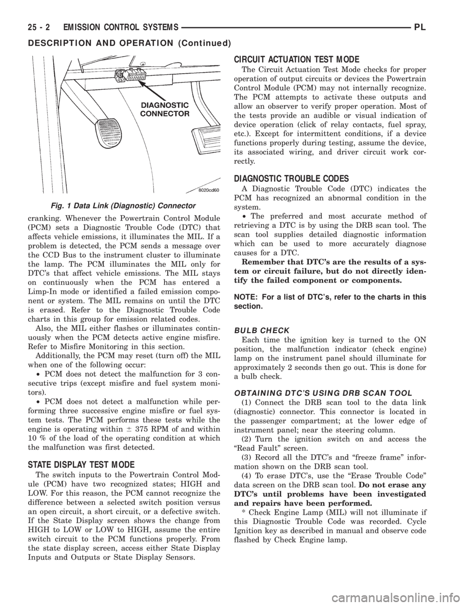
(1) Connect the DRB scan tool to the data link
(diagnostic) connector. This connector is located in
the passenger compartment; at the lower edge of
instrument panel; near the steering column.
(2) Turn the ignition switch on and access the
ªRead Faultº screen.
(3) Record all the DTC's and ªfreeze frameº infor-
mation shown on the DRB scan tool.
(4) To erase DTC's, use the ªErase Trouble Codeº
data screen on the DRB scan tool.Do not erase any
DTC's until problems have been investigated
and repairs have been performed.
* Check Engine Lamp (MIL) will not illuminate if
this Diagnostic Trouble Code was recorded. Cycle
Ignition key as described in manual and observe code
flashed by Check Engine lamp.
Fig. 1 Data Link (Diagnostic) Connector
25 - 2 EMISSION CONTROL SYSTEMSPL
DESCRIPTION AND OPERATION (Continued)
Page 1171 of 1200
reduce the emission of hydrocarbons, oxides of nitro-
gen and carbon monoxide. The catalyst works best
when the air fuel (A/F) ratio is at or near the opti-
mum of 14.7 to 1.
The PCM is programmed to maintain the optimum
air/fuel ratio of 14.7 to 1. This is done by making
short term corrections in the fuel injector pulse width
based on the O2S output. The programmed memory
acts as a self calibration tool that the engine control-
ler uses to compensate for variations in engine spec-
ifications, sensor tolerances and engine fatigue over
the life span of the engine. By monitoring the actual
air-fuel ratio with the O2S (short term) and multiply-
ing that with the program long-term (adaptive) mem-
ory and comparing that to the limit, it can be
determined whether it will pass an emissions test. If
a malfunction occurs such that the PCM cannot
maintain the optimum A/F ratio, then the MIL will
be illuminated.
HEX 70, and B4ÐCATALYST MONITOR
To comply with clean air regulations, vehicles are
equipped with catalytic converters. These converters
reduce the emission of hydrocarbons, oxides of nitro-
gen and carbon monoxide.
Normal vehicle miles or engine misfire can cause a
catalyst to decay. A meltdown of the ceramic core can
cause a reduction of the exhaust passage. This can
increase vehicle emissions and deteriorate engine
performance, driveability and fuel economy.
The catalyst monitor uses dual oxygen sensors
(O2S's) to monitor the efficiency of the converter. The
dual O2Ss strategy is based on the fact that as a cat-
alyst deteriorates, its oxygen storage capacity and its
efficiency are both reduced. By monitoring the oxy-
gen storage capacity of a catalyst, its efficiency can
be indirectly calculated. The upstream O2S is used to
detect the amount of oxygen in the exhaust gas
before the gas enters the catalytic converter. The
PCM calculates the A/F mixture from the output of
the O2S. A low voltage indicates high oxygen content
(lean mixture). A high voltage indicates a low content
of oxygen (rich mixture).
When the upstream O2S detects a lean condition,
there is an abundance of oxygen in the exhaust gas.
A functioning converter would store this oxygen so it
can use it for the oxidation of HC and CO. As the
converter absorbs the oxygen, there will be a lack of
oxygen downstream of the converter. The output of
the downstraem O2S will indicate limited activity in
this condition.
As the converter loses the ability to store oxygen,
the condition can be detected from the behavior of
the downstream O2S. When the efficiency drops, no
chemical reaction takes place. This means the con-
centration of oxygen will be the same downstream as
upstream. The output voltage of the downstreamO2S copies the voltage of the upstream sensor. The
only difference is a time lag (seen by the PCM)
between the switching of the O2S's.
To monitor the system, the number of lean-to-rich
switches of upstream and downstream O2S's is
counted. The ratio of downstream switches to
upstream switches is used to determine whether the
catalyst is operating properly. An effective catalyst
will have fewer downstream switches than it has
upstream switches i.e., a ratio closer to zero. For a
totally ineffective catalyst, this ratio will be one-to-
one, indicating that no oxidation occurs in the device.
The system must be monitored so that when cata-
lyst efficiency deteriorates and exhaust emissions
increase to over the legal limit, the MIL (check
engine lamp) will be illuminated.
HEX A0, A1, B7, and B8ÐLEAK DETECTION
PUMP MONITOR
The leak detection assembly incorporates two pri-
mary functions: it must detect a leak in the evapora-
tive system and seal the evaporative system so the
leak detection test can be run.
The primary components within the assembly are:
A three port solenoid that activates both of the func-
tions listed above; a pump which contains a switch,
two check valves and a spring/diaphragm, a canister
vent valve (CVV) seal which contains a spring loaded
vent seal valve.
Immediately after a cold start, between predeter-
mined temperature thresholds limits, the three port
solenoid is briefly energized. This initializes the
pump by drawing air into the pump cavity and also
closes the vent seal. During non test conditions the
vent seal is held open by the pump diaphragm
assembly which pushes it open at the full travel posi-
tion. The vent seal will remain closed while the
pump is cycling due to the reed switch triggering of
the three port solenoid that prevents the diaphragm
assembly from reaching full travel. After the brief
initialization period, the solenoid is de-energized
allowing atmospheric pressure to enter the pump
cavity, thus permitting the spring to drive the dia-
phragm which forces air out of the pump cavity and
into the vent system. When the solenoid is energized
and de energized, the cycle is repeated creating flow
in typical diaphragm pump fashion. The pump is con-
trolled in 2 modes:
Pump Mode:The pump is cycled at a fixed rate to
achieve a rapid pressure build in order to shorten the
overall test length.
Test Mode:The solenoid is energized with a fixed
duration pulse. Subsequent fixed pulses occur when
the diaphragm reaches the Switch closure point.
The spring in the pump is set so that the system
will achieve an equalized pressure of about 7.5º H20.
The cycle rate of pump strokes is quite rapid as the
25 - 8 EMISSION CONTROL SYSTEMSPL
DESCRIPTION AND OPERATION (Continued)
Page 1175 of 1200
PRESSURE-VACUUM FILLER CAP
CAUTION: Remove the fuel filler cap to relieve fuel
tank pressure. The cap must be removed prior to
disconnecting any fuel system component or ser-
vicing the fuel tank.
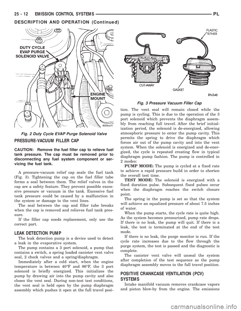
A pressure-vacuum relief cap seals the fuel tank
(Fig. 3). Tightening the cap on the fuel filler tube
forms a seal between them. The relief valves in the
cap are a safety feature. They prevent possible exces-
sive pressure or vacuum in the tank. Excessive fuel
tank pressure could be caused by a malfunction in
the system or damage to the vent lines.
The seal between the cap and filler tube breaks
when the cap is removed and relieves fuel tank pres-
sure.
If the filler cap needs replacement, only use the
correct part.
LEAK DETECTION PUMP
The leak detection pump is a device used to detect
a leak in the evaporative system.
The pump contains a 3 port solenoid, a pump that
contains a switch, a spring loaded canister vent valve
seal, 2 check valves and a spring/diaphragm.
Immediately after a cold start, when the engine
temperature is between 40ÉF and 86ÉF, the 3 port
solenoid is briefly energized. This initializes the
pump by drawing air into the pump cavity and also
closes the vent seal. During non-test test conditions,
the vent seal is held open by the pump diaphragm
assembly which pushes it open at the full travel posi-tion. The vent seal will remain closed while the
pump is cycling. This is due to the operation of the 3
port solenoid which prevents the diaphragm assem-
bly from reaching full travel. After the brief initial-
ization period, the solenoid is de-energized, allowing
atmospheric pressure to enter the pump cavity. This
permits the spring to drive the diaphragm which
forces air out of the pump cavity and into the vent
system. When the solenoid is energized and de-ener-
gized, the cycle is repeated creating flow in typical
diaphragm pump fashion. The pump is controlled in
2 modes:
PUMP MODE:The pump is cycled at a fixed rate
to achieve a rapid pressure build in order to shorten
the overall test time.
TEST MODE:The solenoid is energized with a
fixed duration pulse. Subsequent fixed pulses occur
when the diaphragm reaches the switch closure
point.
The spring in the pump is set so that the system
will achieve an equalized pressure of about 7.5 inches
of water.
When the pump starts, the cycle rate is quite high.
As the system becomes pressurized, pump rate drops.
If there is no leak, the pump will quit. If there is a
leak, the test is terminated at the end of the test
mode.
If there is no leak, the purge monitor is run. If the
cycle rate increases due to the flow through the
purge system, the test is passed and the diagnostic is
complete.
The canister vent valve will unseal the system
after completion of the test sequence as the pump
diaphragm assembly moves to the full travel position.
POSITIVE CRANKCASE VENTILATION (PCV)
SYSTEMS
Intake manifold vacuum removes crankcase vapors
and piston blow-by from the engine. The emissions
Fig. 2 Duty Cycle EVAP Purge Solenoid Valve
Fig. 3 Pressure Vacuum Filler Cap
25 - 12 EMISSION CONTROL SYSTEMSPL
DESCRIPTION AND OPERATION (Continued)
Page 1176 of 1200
pass through the PCV valve into the intake manifold
where they become part of the calibrated air-fuel
mixture. They are burned and expelled with the
exhaust gases. The air cleaner supplies make up air
when the engine does not have enough vapor or
blow-by gases. In this system, fresh air does not
enter the crankcase.
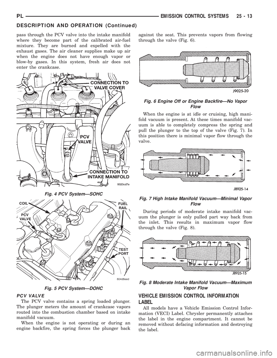
PCV VALVE
The PCV valve contains a spring loaded plunger.
The plunger meters the amount of crankcase vapors
routed into the combustion chamber based on intake
manifold vacuum.
When the engine is not operating or during an
engine backfire, the spring forces the plunger backagainst the seat. This prevents vapors from flowing
through the valve (Fig. 6).
When the engine is at idle or cruising, high mani-
fold vacuum is present. At these times manifold vac-
uum is able to completely compress the spring and
pull the plunger to the top of the valve (Fig. 7). In
this position there is minimal vapor flow through the
valve.
During periods of moderate intake manifold vac-
uum the plunger is only pulled part way back from
the inlet. This results in maximum vapor flow
through the valve (Fig. 8).
VEHICLE EMISSION CONTROL INFORMATION
LABEL
All models have a Vehicle Emission Control Infor-
mation (VECI) Label. Chrysler permanently attaches
the label in the engine compartment. It cannot be
removed without defacing information and destroying
the label.
Fig. 4 PCV SystemÐSOHC
Fig. 5 PCV SystemÐDOHC
Fig. 6 Engine Off or Engine BackfireÐNo Vapor
Flow
Fig. 7 High Intake Manifold VacuumÐMinimal Vapor
Flow
Fig. 8 Moderate Intake Manifold VacuumÐMaximum
Vapor Flow
PLEMISSION CONTROL SYSTEMS 25 - 13
DESCRIPTION AND OPERATION (Continued)