1999 DODGE NEON ECO mode
[x] Cancel search: ECO modePage 945 of 1200
CAUTION: The transaxle output shaft is serviced as
a unit. No disassembly and reassembly is possible.
Damage to the transaxle may result.
TRANSAXLE IDENTIFICATION INFORMATION
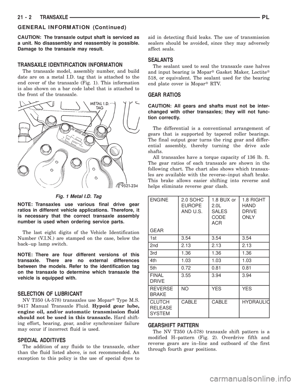
The transaxle model, assembly number, and build
date are on a metal I.D. tag that is attached to the
end cover of the transaxle (Fig. 1). This information
is also shown on a bar code label that is attached to
the front of the transaxle.
NOTE: Transaxles use various final drive gear
ratios in different vehicle applications. Therefore, it
is necessary that the correct transaxle assembly
number is used when ordering service parts.
The last eight digits of the Vehicle Identification
Number (V.I.N.) are stamped on the case, below the
back±up lamp switch.
NOTE: There are four different versions of this
transaxle. There are no external differences
between the models. Refer to the identification tag
on the transaxle to determine which transaxle the
vehicle is equipped with.
SELECTION OF LUBRICANT
NV T350 (A-578) transaxles use MopartType M.S.
9417 Manual Transaxle Fluid.Hypoid gear lube,
engine oil, and/or automatic transmission fluid
should not be used in this transaxle.Hard shift-
ing effort, bearing, gear, and/or synchronizer failure
may occur if incorrect fluid is used.
SPECIAL ADDITIVES
The addition of any fluids to the transaxle, other
than the fluid listed above, is not recommended. An
exception to this policy is the use of special dyes toaid in detecting fluid leaks. The use of transmission
sealers should be avoided, since they may adversely
affect seals.
SEALANTS
The sealant used to seal the transaxle case halves
and input bearing is MopartGasket Maker, Loctitet
518, or equivalent. The sealant used for the bearing
end plate cover is MopartRTV.
GEAR RATIOS
CAUTION: All gears and shafts must not be inter-
changed with other transaxles; they will not func-
tion correctly.
The differential is a conventional arrangement of
gears that is supported by tapered roller bearings.
The final output gear turns the ring gear and differ-
ential assembly, thereby turning the drive axle
shafts.
All transaxles have a torque capacity of 136 lb. ft.
The gear ratios of each transaxle are shown in the
following chart. The chart also shows which transax-
les are available with the reverse±input shaft brake.
This brake allows easier shifting into reverse and
helps eliminate reverse gear clash.
ENGINE 2.0 SOHC
EUROPE
AND U.S.1.8 BUX or
2.0L
SALES
CODE
ACR1.8 RIGHT
HAND
DRIVE
ONLY
GEAR
1st 3.54 3.54 3.54
2nd 2.13 2.13 2.13
3rd 1.36 1.36 1.36
4th 1.03 1.03 1.03
5th 0.72 0.81 0.81
FINAL
DRIVE3.55 3.94 3.94
REVERSE
BRAKENO YES YES
CLUTCH
RELEASE
SYSTEMCABLE CABLE HYDRAULIC
GEARSHIFT PATTERN
The NV T350 (A-578) transaxle shift pattern is a
modified H±pattern (Fig. 2). Overdrive fifth and
reverse gears are in±line and outboard of the first
through fourth gear positions.
Fig. 1 Metal I.D. Tag
21 - 2 TRANSAXLEPL
GENERAL INFORMATION (Continued)
Page 984 of 1200
NOTE: Transaxle operation requirements are differ-
ent for each vehicle and engine combination. Some
internal parts will be different to provide for this.
Therefore, when replacing parts, refer to the seven
digit part number stamped on rear of the transaxle
oil pan flange.
Within this transaxle, there are three primary
areas:
(1) Main center line plus valve body.
(2) Transfer shaft center line (includes governor
and parking sprag).
(3) Differential center line.
Center distances between the main rotating parts
in these three areas are held precise to maintain a
low noise level.
The torque converter, transaxle area, and differen-
tial are housed in an integral aluminum die casting.
The differential oil sump is common with the
transaxle sump. Separate filling of the differen-
tial is NOT necessary.
The torque converter is attached to the crankshaft
through a flexible driving plate. Cooling of the con-
verter is accomplished by circulating the transaxle
fluid through a remote cooler. There are two types of
coolers used. An oil-to-water type cooler located in
the radiator side tank and/or an oil-to-air heat
exchanger. The torque converter assembly is a sealed
unit that cannot be disassembled.
The transaxle fluid is filtered by an internal filter
attached to the lower side of the valve body assembly.
Engine torque is transmitted to the torque con-
verter and then through the input shaft to multiple-
disc clutches in the transaxle. The power flow
depends on the application of the clutches and bands.
Refer to Elements in Use Chart in Diagnosis and
Tests section.
The transaxle consists of:
²Two multiple-disc clutches
²An overrunning clutch
²Two servos
²A hydraulic accumulator
²Two bands
²Two planetary gear sets
This provides three forward ratios and a reverse
ratio. The common sun gear of the planetary gear
sets is connected to the front clutch by a driving
shell. The driving shell is splined to the sun gear and
front clutch retainer. The hydraulic system consists
of an oil pump and a single valve body which con-
tains all of the valves except the governor valves.
The transaxle sump and differential sump are both
vented through the dipstick. Output torque from the
main center line is delivered through helical gears to
the transfer shaft. This gear set is a factor in the
transaxle final drive (axle) ratio. The shaft also car-
ries the governor and parking sprag. An integral heli-cal gear on the transfer shaft drives the differential
ring gear. The final drive gearing is completed with
one of two gear ratios; 2.98 or 3.19 depending on
model and application.
FLUID LEVEL AND CONDITION
NOTE: The transmission and differential sump have
a common oil sump with a communicating opening
between the two.
The torque converter fills in both the P (Park) and
N (Neutral) positions. Place the selector lever in P
(Park) to be sure that the fluid level check is accu-
rate.The engine should be running at idle
speed for at least one minute, with the vehicle
on level ground. This will ensure complete oil
level stabilization between differential and
transmission.The fluid should be at normal operat-
ing temperature (approximately 82É C. or 180É F.).
The fluid level is correct if it is in the HOT region
(cross-hatched area) on the dipstick.
Low fluid level can cause a variety of conditions,
because it allows the pump to take in air along with
the fluid. As in any hydraulic system, air bubbles
make the fluid spongy therefore, pressures will be
low and will build up slowly.
Improper filling also can raise the fluid level too
high. When the transaxle has too much fluid, the
gears churn up foam and cause the same conditions
that occur with a low fluid level.
In either case, the air bubbles can cause overheat-
ing, fluid oxidation, and varnishing. This can inter-
fere with normal valve, clutch, and servo operation.
Foaming also can result in fluid escaping from the
transaxle dipstick, where it may be mistaken for a
leak.
Along with fluid level, it is important to check the
condition of the fluid. When the fluid smells burned,
or is contaminated with metal or friction material
particles, a complete transaxle overhaul is needed.
Be sure to examine the fluid on the dipstick closely.
If there is any doubt about its condition, drain out a
sample for a double check.
SELECTION OF LUBRICANT
It is important that the proper lubricant be used in
these transmissions. Mopar ATF PLUS 3 (Automatic
Transmission Fluid- type 7176) should be used to aid
in ensuring optimum transmission performance. It is
important that the transmission fluid be maintained
at the prescribed level using the recommended fluids.
SPECIAL ADDITIVES
Chrysler Corporation does not recommend the
addition of any fluids to the transmission, other than
that fluid listed above. An exception to this policy is
PLTRANSAXLE 21 - 41
GENERAL INFORMATION (Continued)
Page 1134 of 1200
HEATING AND AIR CONDITIONING
CONTENTS
page page
GENERAL INFORMATION
INTRODUCTION......................... 2
SAFETY PRECAUTIONS AND WARNINGS..... 2
DESCRIPTION AND OPERATION
A/C REFRIGERANT LINES................. 3
BLOWER MOTOR RESISTOR............... 3
COMPRESSOR FRONT SHAFT SEAL......... 4
COMPRESSOR.......................... 4
CONDENSATION DRAIN TUBE.............. 4
ENGINE COOLING SSTEM
REQUIREMENTS....................... 4
EVAPORATOR PROBE..................... 4
HANDLING TUBING AND FITTINGS.......... 4
HIGH PRESSURE CUT OUT SWITCH......... 5
LOW PRESSURE CUT OFF SWITCH......... 5
SIDE WINDOW DEMISTERS............... 5
SYSTEM AIRFLOW....................... 5
SYSTEM OIL LEVEL...................... 6
VACUUM CONTROL SYSTEM............... 6
DIAGNOSIS AND TESTING
A/C PERFORMANCE TEST................. 6
BLOWER MOTOR ELECTRICAL DIAGNOSIS . . . 8
BLOWER MOTOR VIBRATION
AND/OR NOISE DIAGNOSIS.............. 8
COMPRESSOR NOISE DIAGNOSIS.......... 7
EVAPORATOR PROBE TEST................ 8
EXPANSION VALVE....................... 7
HEATER PERFORMANCE TEST............. 8
LOW PRESSURE CUT-OFF SWITCH......... 11
SYSTEM CHARGE LEVEL TEST............ 11
VACUUM CONTROL SYSTEM.............. 12
SERVICE PROCEDURES
CHARGING A/C SYSTEM................. 14
EVACUATING REFRIGERANT SYSTEM....... 15R-134a REFRIGERANT................... 16
SERVICING REFRIGERANT OIL LEVEL...... 17
SYSTEM LEAK CHECKING................ 17
REMOVAL AND INSTALLATION
A/C FILTER/DRIER...................... 23
A/C SERVICE PORT VALVE CORES......... 18
BLOWER MOTOR AND WHEEL ASSEMBLY . . . 18
BLOWER MOTOR RESISTOR.............. 18
BLOWER MOTOR WHEEL................ 19
COMPRESSOR CLUTCH/COIL ASSEMBLY.... 19
COMPRESSOR......................... 19
CONDENSATION DRAIN TUBE............ 21
CONDENSER........................... 21
DISCHARGE LINE....................... 21
EVAPORATOR PROBE.................... 22
EVAPORATOR.......................... 21
EXPANSION VALVE...................... 23
HEATER CORE......................... 24
HEATER HOSES........................ 24
HIGH PRESSURE CUT OUT SWITCH........ 23
HIGH PRESSURE RELIEF VALVE........... 24
LIQUID LINE........................... 25
LOW PRESSURE CUT OFF SWITCH........ 25
MODE CONTROL CABLE................. 25
RECIRCULATION DOOR ACTUATOR........ 26
SUCTION LINE......................... 27
TEMPERATURE CONTROL CABLE.......... 27
UNIT HOUSING......................... 27
DISASSEMBLY AND ASSEMBLY
AIR DISTRIBUTION MODULE ±
RECONDITION........................ 28
ADJUSTMENTS
MODE CONTROL CABLE................. 30
TEMPERATURE CONTROL CABLE.......... 30
PLHEATING AND AIR CONDITIONING 24 - 1
Page 1135 of 1200
GENERAL INFORMATION
INTRODUCTION
Both the heater and the heater/air conditioning
systems share many of the same functioning compo-
nents. This group will deal with both systems
together when component function is common, and
separately when they are not.
For proper operation of the instrument panel con-
trols, refer to the Owner's Manual provided with the
vehicle.
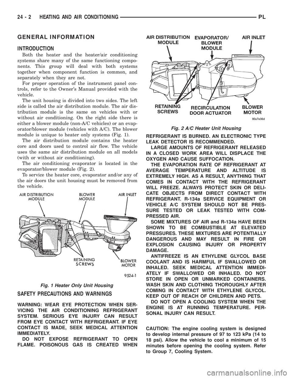
The unit housing is divided into two sides. The left
side is called the air distribution module. The air dis-
tribution module is the same on vehicles with or
without air conditioning. On the right side there is
either a blower module (non-A/C vehicles) or an evap-
orator/blower module (vehicles with A/C). The blower
module is unique to heater only systems (Fig. 1).
The air distribution module contains the heater
core and doors used to control air flow. The vehicle
uses the same air distribution module on all models
(with or without air conditioning).
The air conditioning evaporator is located in the
evaporator/blower module (Fig. 2).
To service the heater core, evaporator and/or any of
the air doors the unit housing must be removed from
the vehicle.
SAFETY PRECAUTIONS AND WARNINGS
WARNING: WEAR EYE PROTECTION WHEN SER-
VICING THE AIR CONDITIONING REFRIGERANT
SYSTEM. SERIOUS EYE INJURY CAN RESULT
FROM EYE CONTACT WITH REFRIGERANT. IF EYE
CONTACT IS MADE, SEEK MEDICAL ATTENTION
IMMEDIATELY.
DO NOT EXPOSE REFRIGERANT TO OPEN
FLAME. POISONOUS GAS IS CREATED WHENREFRIGERANT IS BURNED. AN ELECTRONIC TYPE
LEAK DETECTOR IS RECOMMENDED.
LARGE AMOUNTS OF REFRIGERANT RELEASED
IN A CLOSED WORK AREA WILL DISPLACE THE
OXYGEN AND CAUSE SUFFOCATION.
THE EVAPORATION RATE OF REFRIGERANT AT
AVERAGE TEMPERATURE AND ALTITUDE IS
EXTREMELY HIGH. AS A RESULT, ANYTHING THAT
COMES IN CONTACT WITH THE REFRIGERANT
WILL FREEZE. ALWAYS PROTECT SKIN OR DELI-
CATE OBJECTS FROM DIRECT CONTACT WITH
REFRIGERANT. R-134a SERVICE EQUIPMENT OR
VEHICLE A/C SYSTEM SHOULD NOT BE PRES-
SURE TESTED OR LEAK TESTED WITH COM-
PRESSED AIR.
SOME MIXTURES OF AIR and R-134a HAVE BEEN
SHOWN TO BE COMBUSTIBLE AT ELEVATED
PRESSURES. THESE MIXTURES ARE POTENTIALLY
DANGEROUS AND MAY RESULT IN FIRE OR
EXPLOSION CAUSING INJURY OR PROPERTY
DAMAGE.
ANTIFREEZE IS AN ETHYLENE GLYCOL BASE
COOLANT AND IS HARMFUL IF SWALLOWED OR
INHALED. SEEK MEDICAL ATTENTION IMMEDI-
ATELY IF SWALLOWED OR INHALED. DO NOT
STORE IN OPEN OR UNMARKED CONTAINERS.
WASH SKIN AND CLOTHING THOROUGHLY AFTER
COMING IN CONTACT WITH ETHYLENE GLYCOL.
KEEP OUT OF REACH OF CHILDREN AND PETS.
DO NOT OPEN A COOLING SYSTEM WHEN THE
ENGINE IS AT RUNNING TEMPERATURE. PER-
SONAL INJURY CAN RESULT.
CAUTION: The engine cooling system is designed
to develop internal pressure of 97 to 123 kPa (14 to
18 psi). Allow the vehicle to cool a minimum of 15
minutes before opening the cooling system. Refer
to Group 7, Cooling System.
Fig. 2 A/C Heater Unit Housing
Fig. 1 Heater Only Unit Housing
24 - 2 HEATING AND AIR CONDITIONINGPL
Page 1137 of 1200
COMPRESSOR
The compressor used on this vehicle is a Nippon-
denso 10PA17 R-134a. This compressor uses an alu-
minum swash plate, teflon coated pistons and
aluminum sleeved cylinder walls.
CAUTION: A 10PA17 R-12 compressor looks identi-
cal to a 10PA17 R-134a and will bolt up to the vehi-
cle. The 10PA17 R-12 compressor must not be used
on this system. It is extremely important that a
10PA17 R-134a compressor is identified prior to
using compressor in question. Check tag located
on compressor for model number.
NOISE
Excessive noise that occurs when the air condition-
ing is being used may be caused by:
²Loose bolts
²Mounting brackets
²Loose compressor clutch
²Excessive high refrigerant operating pressure
Verify the following before compressor repair is
performed:
(1) Compressor drive belt condition
(2) Proper refrigerant charge
(3) Thermal expansion valve (TXV) operating cor-
rectly
(4) Head pressure is normal
COMPRESSOR FRONT SHAFT SEAL
The compressor front shaft seal is not serviceable.
If a leak is detected at the shaft seal, the compressor
must be replaced as a unit.
CONDENSATION DRAIN TUBE
Condensation that accumulates in the evaporator
housing is drained from a tube through the dash and
on to the ground. This tube must be kept open to
prevent condensate water from collecting in the bot-
tom of the housing.
The tapered end of the drain tube is designed to
keep contaminants from entering the heater A/C unit
housing. If the tube is pinched or blocked, condensate
cannot drain, causing water to back up and spill into
the passenger compartment. It is normal to see con-
densate drainage below the vehicle. If the tube is
damaged, it should be replaced.
ENGINE COOLING SYSTEM REQUIREMENTS
To maintain ample temperature levels from the
heating-A/C system, the cooling system must be in
proper working order. Refer to Group 0, Lubrication
and Maintenance or Group 7, Cooling System of this
manual.
The use of a bug screen is not recommended. Any
obstructions forward of the condenser can reduce the
effectiveness of the air conditioning system.
EVAPORATOR PROBE
The evaporator probe can be replaced without hav-
ing to remove the unit housing from the vehicle.
The evaporator probe is located in the unit housing
and placed in the evaporator fins. The probe prevents
evaporator freeze-up. This is done by cycling the com-
pressor clutch OFF when evaporator temperature
drops below freeze point. It cycles ON when the
evaporator temperature rises above freeze point. The
evaporator probe uses a thermistor probe in a capil-
lary tube. The tube is inserted between the evapora-
tor fins in the heater-A/C unit housing.
HANDLING TUBING AND FITTINGS
Kinks in the refrigerant tubing or sharp bends in
the refrigerant hose lines will greatly reduce the
capacity of the entire system. High pressures are pro-
duced in the system when it is operating. Extreme
care must be exercised to make sure that all connec-
tions are pressure tight. Dirt and moisture can enter
the system when it is opened for repair or replace-
ment of lines or components. The refrigerant oil will
absorb moisture readily out of the air. This moisture
will convert into acids within a closed system.
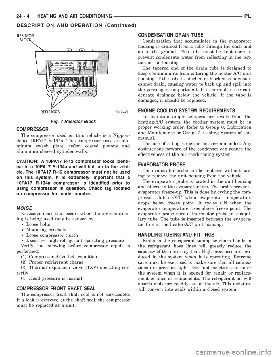
Fig. 7 Resistor Block
24 - 4 HEATING AND AIR CONDITIONINGPL
DESCRIPTION AND OPERATION (Continued)
Page 1145 of 1200
WARNING: AVOID BREATHING A/C REFRIGERANT
AND LUBRICANT VAPOR OR MIST. EXPOSURE MAY
IRRITATE EYES, NOSE AND THROAT. USE ONLY
APPROVED SERVICE EQUIPMENT MEETING SAE
REQUIREMENTS TO DISCHARGE R-134a SYSTEM.
IF ACCIDENTAL SYSTEM DISCHARGE OCCURS,
VENTILATE WORK AREA BEFORE RESUMING SER-
VICE.
R-134a SERVICE EQUIPMENT OR VEHICLE A/C
SYSTEM SHOULD NOT BE PRESSURE TESTED OR
LEAK TESTED WITH COMPRESSED AIR. MIXTURE
OF AIR and R-134a CAN BE COMBUSTIBLE AT ELE-
VATED PRESSURES. THESE MIXTURES ARE
POTENTIALLY DANGEROUS AND MAY RESULT IN
FIRE OR EXPLOSION CAUSING INJURY OR PROP-
ERTY DAMAGE.
NOTE: The maximum amount of R-134a refrigerant
that the air conditioning system holds is 784 grams
(28 oz. or 1.57 lbs.)
It is recommended to use the gauges or reclaim/re-
cycle equipment.
(1) Use a manifold gauge and check the liquid line
pressure.
(2) Attach a clamp-on thermocouple (P.S.E. 66-324-
0014 or 80PK-1A) or equivalent to the liquid line
near the filter/drier.
(3) The vehicle must be in the following modes:
²Automatic transaxle in park or manual tran-
saxle in neutral.
²Engine at idle
²A/C controls set to outside air
²Panel mode
²A/C ON full cool
²Blower motor ON high speed
²Vehicle windows closed
(4) Operate system for a couple of minutes to allow
the system to stabilize.
(5) Observe filter/drier pressure and Liquid line
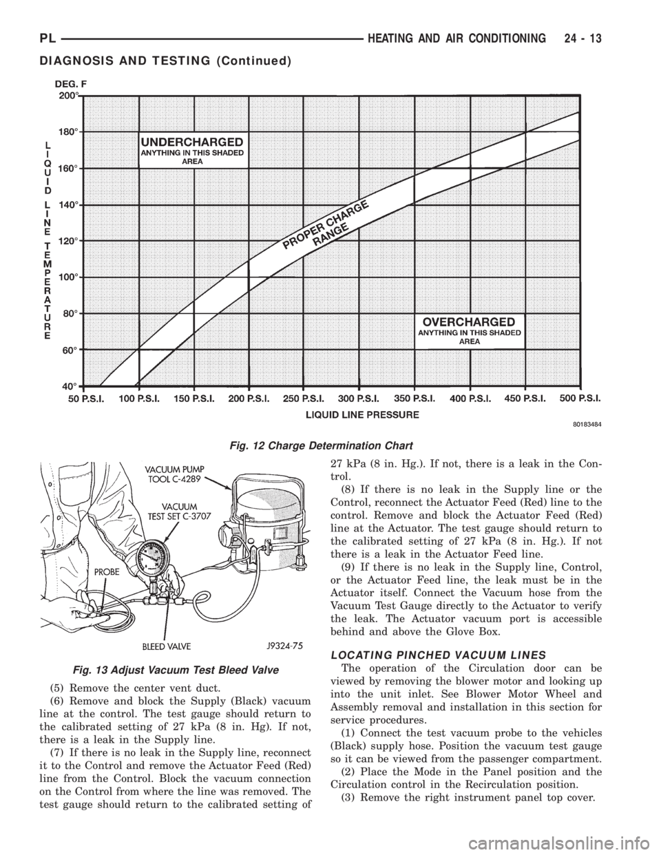
temperature. Using the Charge Determination Chart
(Fig. 12) determine where the system is currently
operating. If the system is not in the proper range,
reclaim all the refrigerant and recharge per A/C label
.
VACUUM CONTROL SYSTEM
Use an adjustable vacuum test set (Special Tool
C-3707) and a suitable vacuum pump to test the
heater-A/C vacuum control system. With a finger
placed over the end of the vacuum test hose probe
(Fig. 13), adjust the bleed valve on the test set gauge
to obtain a vacuum of exactly 27 kPa (8 in. Hg.).
Release and block the end of the probe several times
to verify that the vacuum reading returns to theexact 27 kPa (8 in. Hg.) setting. Otherwise, a false
reading will be obtained during testing.
ONE-WAY CHECK VALVE
(1) Disconnect the heater-A/C vacuum supply
(Black) tube in the engine compartment. This tube
passes through an opening in the dash panel.
(2) Remove the one-way vacuum check valve. The
valve is located on the (Black) vacuum supply hose at
the brake power booster.
(3) Connect the test set vacuum supply hose to the
heater side of the valve. When connected to this side
of the check valve, no vacuum should pass and the
test set gauge should return to the 27 kPa (8 in. Hg.)
setting. If OK, go to step Step 4. If not OK, replace
the faulty valve.
(4) Connect the test set vacuum supply hose to the
engine vacuum side of the valve. When connected to
this side of the check valve, vacuum should flow
through the valve without restriction. If not OK,
replace the faulty valve.
HEATER-A/C CONTROLS
The operation of the Circulation door can be
viewed by removing the blower motor and looking up
into the unit inlet. See Blower Motor Wheel and
Assembly removal and installation in this section for
service procedures.
(1) Connect the test set vacuum probe to the heat-
er-A/C vacuum supply (Black) hose in the engine
compartment. Position the test set gauge so that it
can be viewed from the passenger compartment.
(2) Start with the Mode control in the Panel posi-
tion and the Circulation control in the Ouside-air
position.
(3) Move the Circulation control to the Recircula-
tion position (the Circulation door should move into
the Recirculation position). After a short pause move
the Mode control to the Defrost position (the Circula-
tion door should move to the Outside-air position).
The test gauge should return to the calibrated set-
ting of 27 kPa (8in. Hg.) after each selection is made.
If the gauge cannot achieve the calibrated setting,
the vacuum circuit or a component has a leak.
(4) If the gauge achieves the calibrated setting but
the door does not move, there is either a pinched vac-
uum line or a failed actuator.
LOCATING VACUUM LEAKS
(1) Connect the test vacuum probe to the vehicles
(Black) supply hose. Position the vacuum test gauge
so it can be viewed from the passenger compartment.
(2) Place the Mode in the Panel position and the
Circulation control in the Recirculation position.
(3) Remove the instrument panel top cover.
(4) Remove the right side upper instrument panel
bezel.
24 - 12 HEATING AND AIR CONDITIONINGPL
DIAGNOSIS AND TESTING (Continued)
Page 1146 of 1200
(5) Remove the center vent duct.
(6) Remove and block the Supply (Black) vacuum
line at the control. The test gauge should return to
the calibrated setting of 27 kPa (8 in. Hg). If not,
there is a leak in the Supply line.
(7) If there is no leak in the Supply line, reconnect
it to the Control and remove the Actuator Feed (Red)
line from the Control. Block the vacuum connection
on the Control from where the line was removed. The
test gauge should return to the calibrated setting of27 kPa (8 in. Hg.). If not, there is a leak in the Con-
trol.
(8) If there is no leak in the Supply line or the
Control, reconnect the Actuator Feed (Red) line to the
control. Remove and block the Actuator Feed (Red)
line at the Actuator. The test gauge should return to
the calibrated setting of 27 kPa (8 in. Hg.). If not
there is a leak in the Actuator Feed line.
(9) If there is no leak in the Supply line, Control,
or the Actuator Feed line, the leak must be in the
Actuator itself. Connect the Vacuum hose from the
Vacuum Test Gauge directly to the Actuator to verify
the leak. The Actuator vacuum port is accessible
behind and above the Glove Box.
LOCATING PINCHED VACUUM LINES
The operation of the Circulation door can be
viewed by removing the blower motor and looking up
into the unit inlet. See Blower Motor Wheel and
Assembly removal and installation in this section for
service procedures.
(1) Connect the test vacuum probe to the vehicles
(Black) supply hose. Position the vacuum test gauge
so it can be viewed from the passenger compartment.
(2) Place the Mode in the Panel position and the
Circulation control in the Recirculation position.
(3) Remove the right instrument panel top cover.
Fig. 12 Charge Determination Chart
Fig. 13 Adjust Vacuum Test Bleed Valve
PLHEATING AND AIR CONDITIONING 24 - 13
DIAGNOSIS AND TESTING (Continued)
Page 1147 of 1200
(4) Remove the right side upper instrument panel
bezel.
(5) Remove the center vent duct.
(6) Remove the Supply (Black) vacuum line at the
control. The test gauge should drop indicating free
flow through the Supply line. If not, there is a block-
age in the Supply line.
(7) If there is no blockage in the Supply line,
reconnect it to the Control. Remove the Actuator
Feed (Red) line from the Control. The test gauge
should drop indicating free flow through the Supply
line and Control. If not the vacuum switches on the
Control are not functioning.
(8) If there is no blockage in the Supply line or the
Control, reconnect the Actuator Feed (Red) line to the
control. Remove the Actuator Feed (Red) line at the
Actuator. The Actuator vacuum port is accessible
behind and above the Glove Box. The test guage
should drop indicating free flow through the supply
line, Control, and the Actuator Feed line. If not,
there is a blockage in the Actuator Feed line.
(9) If there is no blockage in the Supply line, Con-
trol, or the Actuator Feed line, the Actuator must
have failed. Connect the Vacuum hose from the Vac-
uum Test Gauge directly to the Actuator to verify the
Actuator has failed.
SERVICE PROCEDURES
CHARGING A/C SYSTEM
PARTIAL CHARGE
This vehicle does not have a sight glass. It is not
possible to determine the amount of (R-134a) chargein the system. Therefore it is necessary to completely
evacuate and recover the system, and then recharge
the system fully.
EVACUATION
Before adding refrigerant, all air must be evacu-
ated from the system.
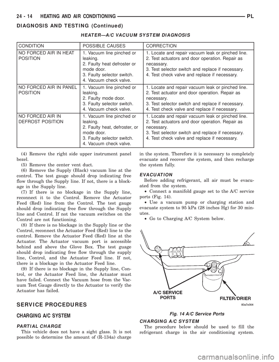
²Connect a manifold gauge set to the A/C service
ports (Fig. 14).
²Use a vacuum pump or charging station and
evacuate system to 95 kPa (28 inches Hg) for 30 min-
utes.
²Go to Charging A/C System below.
CHARGING A/C SYSTEM
The procedure below should be used to fill the
refrigerant charge in the air conditioning system.
HEATERÐA/C VACUUM SYSTEM DIAGNOSIS
CONDITION POSSIBLE CAUSES CORRECTION
NO FORCED AIR IN HEAT
POSITION1. Vacuum line pinched or
leaking.
2. Faulty heat defroster or
mode door.
3. Faulty selector switch.
4. Vacuum check valve.1. Locate and repair vacuum leak or pinched line.
2. Test actuators and door operation. Repair as
necassary.
3. Test selector switch and replace if necessary.
4. Test check valve and replace if necessary.
NO FORCED AIR IN PANEL
POSITION1. Vacuum line pinched or
leaking.
2. Faulty mode door.
3. Faulty selector switch.
4. Vacuum check valve.1. Locate and repair vacuum leak or pinched line.
2. Test actuator and door operation. Repair as
necessary.
3. Test selector switch and replace if necessary.
4. Test check valve and replace if necessary.
NO FORCED AIR IN
DEFROST POSITION1. Vacuum line pinched or
leaking.
2. Faulty heat, defroster, or
mode door.
3. Faulty selector switch.
4. Vacuum check valve.1. Locate and repair vacuum leak or pinched line.
2. Test actuators and door operation. Repair as
necessary.
3. Test selector switch and replace if necessary.
4. Test check valve and replace if necessary.
Fig. 14 A/C Service Ports
24 - 14 HEATING AND AIR CONDITIONINGPL
DIAGNOSIS AND TESTING (Continued)