1999 DODGE NEON ECO mode
[x] Cancel search: ECO modePage 299 of 1200
SPEED CONTROL SWITCHES
There are two separate switch pods that operate
the speed control system. The steering-wheel-
mounted switches use multiplexed circuits to provide
inputs to the PCM for ON, OFF, RESUME, ACCEL-
ERATE, SET, DECEL and CANCEL modes. Refer to
the owner's manual for more information on speed
control switch functions and setting procedures.When speed control is selected by depressing the
ON switch, the PCM allows a set speed to be stored
in RAM for speed control. To store a set speed,
depress the SET switch while the vehicle is moving
at a speed between 30 and 85 mph. In order for the
speed control to engage, the brakes cannot be
applied, nor can the gear selector be indicating the
transmission is in Park or Neutral.
The speed control can be disengaged manually by:
²Stepping on the brake pedal
²Depressing the OFF switch
²Depressing the CANCEL switch.
NOTE: Depressing the OFF switch or turning off
the ignition switch will erase the set speed stored
in the PCM.
For added safety,the speed control system is pro-
grammed to disengaged for any of the following con-
ditions:
²An indication of Park or Neutral
²An rpm increase without a VSS signal increase
(indicates that the clutch has been disengaged)
²Excessive engine rpm (indicates that the trans-
mission may be in a low gear)
²The VSS signal increases at a rate of 10 mph
per second (indicates that the co-efficient of friction
between the road surface and tires is extremely low)
²The VSS signal decreases at a rate of 10 mph
per second (indicates that the vehicle may have
decelerated at an extremely high rate)
²If the actual speed is not within 20 mph of the
set speed
The previous disengagement conditions are pro-
grammed for added safety.
Once the speed control has been disengaged,
depressing the ACCEL switch when speed is greater
than 25 mph restores the vehicle to the target speed
that was stored in the PCM.
NOTE: Depressing the OFF switch will erase the
set speed stored in the PCM's RAM.
While the speed control is engaged, the driver can
increase the vehicle speed by depressing the ACCEL
switch. The new target speed is stored in the PCM
when the ACCEL is released. The PCM also has a
9tap-up9feature in which vehicle speed increases at a
rate of approximately 2 mph for each momentary
switch activation of the ACCEL switch. The PCM
also provides a means to decelerate without disen-
gaging speed control. To decelerate from an existing
recorded target speed, depress and hold the COAST
switch until the desired speed is reached, then
release the switch.
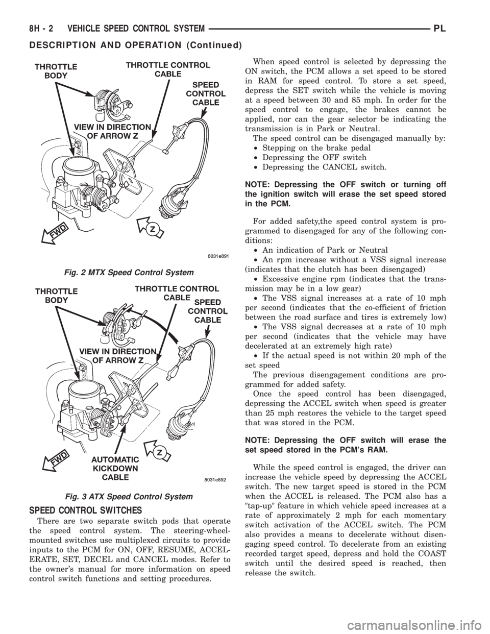
Fig. 2 MTX Speed Control System
Fig. 3 ATX Speed Control System
8H - 2 VEHICLE SPEED CONTROL SYSTEMPL
DESCRIPTION AND OPERATION (Continued)
Page 314 of 1200
WINDSHIELD WIPERS AND WASHERS
CONTENTS
page page
WINDSHIELD WASHER SYSTEM............. 8WINDSHIELD WIPERS..................... 1
WINDSHIELD WIPERS
INDEX
page page
GENERAL INFORMATION
INTRODUCTION......................... 1
DESCRIPTION AND OPERATION
WIPER BLADES.......................... 1
DIAGNOSIS AND TESTING
WINDSHIELD WIPER CONDITION............ 2
WIPER MOTOR.......................... 3
WIPER SWITCH.......................... 5
REMOVAL AND INSTALLATION
WIPER ARM............................. 5WIPER BLADE ELEMENT.................. 5
WIPER BLADE........................... 5
WIPER LINKAGE......................... 6
WIPER MODULE......................... 6
WIPER MOTOR.......................... 6
WIPER SWITCH.......................... 6
CLEANING AND INSPECTION
WIPER BLADES.......................... 6
ADJUSTMENTS
WIPER ARM ADJUSTMENT................. 7
GENERAL INFORMATION
INTRODUCTION
WARNING: VEHICLES ARE EQUIPPED WITH AN
AIRBAG, REFER TO GROUP 8M, RESTRAINT SYS-
TEMS FOR STEERING WHEEL OR COLUMN SER-
VICE PROCEDURES.
The windshield wipers will only operate with the
ignition switch in the ACCESSORY or IGNITION
RUN position. The wiper circuit is protect against
over loads by a fuse in the fuse block and a circuit
breaker within the wiper motor. This protects the cir-
cuitry of the wiper system and the vehicle.
The wiper motor has permanent magnet fields.
The intermittent wiper system, in addition to low
and high speed, has a delay mode and a pulse wipe
mode. The delay mode has a range of 1 to 15 seconds.
Pulse wipe is accomplished by momentarily moving
the stalk lever into the WASH position while the
wiper switch is in either OFF or DELAY position.
The wiper blades then sweep once or twice and
return to the previous wiper switch mode, OFF or
DELAY.The intermittent wiper function is integral to the
wiper switch. All electronics and relay are inside the
switch assembly.
The wiper system completes the wipe cycle when
the switch is turned OFF. The blades park in the
lowest portion of the wipe pattern.
DESCRIPTION AND OPERATION
WIPER BLADES
Wiper blades, exposed to the weather for a long
period of time, tend to lose their wiping effectiveness.
Periodic cleaning of the wiper blade is suggested to
remove the accumulation of salt and road film. The
wiper blades, arms, and windshield should be
cleaned with a sponge or cloth and a mild detergent
or nonabrasive cleaner. If the blades continue to
streak or smear, they should be replaced. The right
and left wipers are different blade lengths. The
driver side length is 525 mm and the passenger side
length is 450 mm. The blades should not be inter-
changed.
PLWINDSHIELD WIPERS AND WASHERS 8K - 1
Page 324 of 1200
WINDSHIELD WIPERS AND WASHERS
CONTENTS
page
WINDSHIELD WIPERS.................... 1
WINDSHIELD WIPERS
INDEX
page page
GENERAL INFORMATION
INTRODUCTION........................ 1
DIAGNOSIS AND TESTING
WINDSHIELD WIPER CONDITION........... 1WIPER MOTOR......................... 3
WIPER SWITCH......................... 5
GENERAL INFORMATION
INTRODUCTION
WARNING: VEHICLES ARE EQUIPPED WITH AN
AIRBAG, REFER TO GROUP 8M, RESTRAINT SYS-
TEMS FOR STEERING WHEEL OR COLUMN SER-
VICE PROCEDURES.
The windshield wipers will only operate with the
ignition switch in the ACCESSORY or IGNITION
RUN position. The wiper circuit is protect against
over loads by a fuse in the fuse block and a circuit
breaker within the wiper motor. This protects the cir-
cuitry of the wiper system and the vehicle.
The wiper motor has permanent magnet fields.
The intermittent wiper system, in addition to low
and high speed, has a delay mode and a pulse wipe
mode. The delay mode has a range of 1 to 15 seconds.
Pulse wipe is accomplished by momentarily moving
the stalk lever into the WASH position while the
wiper switch is in either OFF or DELAY position.
The wiper blades then sweep once or twice and
return to the previous wiper switch mode, OFF or
DELAY.
The intermittent wiper function is integral to the
wiper switch. All electronics and relay are inside the
switch assembly.
The wiper system completes the wipe cycle when
the switch is turned OFF. The blades park in the
lowest portion of the wipe pattern.
DIAGNOSIS AND TESTING
WINDSHIELD WIPER CONDITION
WARNING: ON VEHICLES EQUIPPED WITH AIR-
BAGS, SEE GROUP 8M, RESTRAINT SYSTEMS FOR
STEERING WHEEL OR COLUMN REMOVAL PROCE-
DURES.
The following is a list of general wiper motor sys-
tem problems, the tests that are to be performed to
locate the faulty part, and the corrective action to be
taken.
Whatever the problem, disconnect motor wire har-
ness and clean the terminals, then connect motor
wire harness and test.
MOTOR WILL NOT OPERATE IN SOME OR ALL
SWITCH POSITIONS
(1) Check fuse 15, in the fuse block (Fig. 1).
(a) If fuse is OK, go to Step 2.
(b) If fuse is defective, replace and check motor
operation in all switch positions.
(c) If motor is still inoperative and the fuse does
not blow, go to Step 2.
(d) If replacement fuse blows, go to Step 6.
PLWINDSHIELD WIPERS AND WASHERS 8K - 1
Page 354 of 1200
DIAGNOSIS AND TESTING
AIRBAG SYSTEM TEST
(1) Disconnect and isolate the negative battery
cable.
(2) Connect scan tool (DRB) to Data Link connec-
tor, located at right side of the steering column and
at the lower edge of the lower instrument panel.
(3) Turn the ignition key to ON position. Exit vehi-
cle with scan tool. Use the latest version of the
proper cartridge.
(4) After checking that no one is inside the vehicle,
connect the battery negative terminal.
(5) Using the scan tool, read and record active
diagnostic code data.
(6) Read and record any stored diagnostic codes.
(7) Refer to the Passive Restraint Diagnostic Test
Manual if any diagnostic codes are found in Step 5 or
Step 6.
(8) Erase stored diagnostic codes if there are no
active diagnostic codes. If problems remain, diagnos-
tic codes will not erase. Refer to the Passive
Restraint Diagnostic Test Manual to diagnose the
problem.If the airbag warning lamp either fails
to light with the ignition switch on, or the light
goes on and stays on, there is a system malfunc-
tion. Refer to the Passive Restraint Diagnostic
Test Manual to diagnose the problem.
SERVICE PROCEDURES
CLEANUP PROCEDURE
Roll or fold the passenger airbag towards the
instrument panel surface and close the door over the
folded bag. Then tape the door shut.
Use a vacuum cleaner to remove any residual pow-
der from the vehicle interior. Work from the outside
in to avoid kneeling or sitting in a contaminated
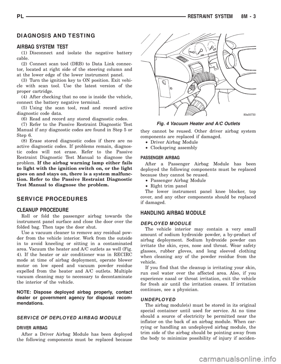
area. Vacuum the heater and A/C outlets as well (Fig.
4). If the heater or air conditioner was in RECIRC
mode at time of airbag deployment, operate blower
motor on low speed and vacuum powder residue
expelled from the heater and A/C outlets. Multiple
vacuum cleaning may to necessary to decontaminate
the interior of the vehicle.
NOTE: Dispose deployed airbag properly, contact
dealer or government agency for disposal recom-
mendations.
SERVICE OF DEPLOYED AIRBAG MODULE
DRIVER AIRBAG
After a Driver Airbag Module has been deployed
the following components must be replaced becausethey cannot be reused. Other driver airbag system
components are replaced if damaged.
²Driver Airbag Module
²Clockspring assembly
PASSENGER AIRBAG
After a Passenger Airbag Module has been
deployed the following components must be replaced
because they cannot be reused.
²Passenger Airbag Module
²Right trim panel
The lower instrument panel knee blocker, top
cover, and any other components should be replaced
if damaged.
HANDLING AIRBAG MODULE
DEPLOYED MODULE
The vehicle interior may contain a very small
amount of sodium hydroxide powder, a by-product of
airbag deployment. Sodium hydroxide powder can
irritate the skin, eyes, nose and throat. Wear safety
glasses, rubber gloves, and long sleeved clothing
when cleaning any of the powder residue from the
vehicle.
If you find that the cleanup is irritating your skin,
run cool water over the affected area. Also, if you
experience nasal or throat irritation, exit the vehicle
for fresh air until the irritation ceases. If irritation
continues, see a physician.
UNDEPLOYED
The airbag module(s) must be stored in its original
special container until used for service. At no time
should a source of electricity be permitted near the
inflator on the back of an airbag module. When car-
rying or handling an undeployed airbag module, the
trim side of the airbag should be pointing away from
the body to minimize possibility of injury if acciden-
Fig. 4 Vacuum Heater and A/C Outlets
PLRESTRAINT SYSTEM 8M - 3
Page 364 of 1200
ELECTRICALLY HEATED SYSTEMS
CONTENTS
page page
DESCRIPTION AND OPERATION
INTRODUCTION......................... 1
REAR WINDOW DEFOGGER SWITCH........ 1
DIAGNOSIS AND TESTING
DEFOGGER SYSTEM..................... 1GRID LINES............................ 2
REAR WINDOW DEFOGGER SWITCH........ 2
SERVICE PROCEDURES
GRID LINE AND TERMINAL REPAIR......... 3
DESCRIPTION AND OPERATION
INTRODUCTION
For proper operation of the Rear Window Defogger
system refer to the Owner's Manual.
The system consists of a rear glass with two verti-
cal bus bars and a series of electrically connected
grid lines fired on the inside surface. A control switch
and a timer relay combined into a single assembly is
used on all models (Fig. 1).
Circuit protection is provided by a maxi fuse,
located in the Power Distribution Center, for the
heated grid circuit and by a fuse for the relay control
circuit.
When the switch is turned to the ON position, cur-
rent is directed to the rear defogger grid lines. The
heated grid lines heat the rear glass to clear the sur-
face of fog or frost.
CAUTION: Grid lines can be damaged or scraped
off with sharp instruments, care should be taken in
cleaning glass or removing foreign materials,
decals or stickers. Normal glass cleaning solvents
or hot water used with rags or toweling is recom-
mended.
REAR WINDOW DEFOGGER SWITCH
The rear window defogger switch is a control
switch and timer relay integrated into a single panel
mounted assembly. Actuating the switch energizes
the circuit which allows current to flow through the
grid lines. Upon initial actuation for approximately
eight to ten minutes, or until either the switch or
ignition is turned off. An indicating lamp illuminates
a lens inlaid in the control switch.
DIAGNOSIS AND TESTING
DEFOGGER SYSTEM
Electrically heated rear window defogger operation
can be checked in vehicle in the following manner:
(1) Turn ignition switch to the ON position.
(2) Connect an ammeter in series with the battery.
Push the defogger control switch to the ON position.
A distinct increase in amperage draw should be
noted.
(3) The rear window defogger operation can be
checked by feeling the glass. A distinct difference in
temperature between the grid lines and adjacent
clear glass can be detected in three to four minutes
of operation.
(4) Using a DC voltmeter, connect negative lead to
Point B, and the positive lead to Point A (Fig. 2). The
voltmeter should read 10-14 volts.
(5) Step 2, Step 3 or Step 4 above will confirm
system operation. Indicator light illumination means
that there is power available at the output of the
relay only, and does not necessarily verify system
operation.
Fig. 1 Rear Window Defogger
PLELECTRICALLY HEATED SYSTEMS 8N - 1
Page 374 of 1200

parking lamps out put. Press the panic button and
check for a voltage pulse (Fig. 2).
(2) If no voltage pulse is measured, replace the
receiver. If voltage OK, repair circuit to the parking
lamps as necessary.
(3) Connect the meter to Pin 5 of the black connec-
tor and to ground to test head lamps out put. Press
the panic button and check for a voltage pulse (Fig.
2).
(4) If no voltage pulse is measured, replace the
receiver. If voltage OK, repair circuit to the head
lamps as necessary.
REMOTE KEYLESS ENTRY SYSTEM
When trouble shooting problems with the Remote
Keyless Entry System, always verify that the power
door lock/unlock switches are functional. If the doors
do not lock/unlock refer to Group 8W, Wiring Dia-
gram for Pin and wiring locations.
If the following items do not work:
²Remote keyless entry system
²Radio/clock
²Door lock switches
A blown fuse is the probable cause. Check fuses 2,
3 and 11 in the fuse block. To check for a blown fuse,
pull the fuse out slightly, but maintain contact
between the fuse terminals and the terminals in fuse
block. Using the voltmeter probe, check both termi-
nals for 12 volts. If only one terminal measures bat-
tery voltage, the circuit breaker is defective and must
be replaced. If neither terminal measures battery
voltage, check the high current fuses 3 and 11 in the
Power Distribution Center (PDC). The PDC is located
in the engine compartment. If fuse(s) are NOT OK,
replace fuse(s) or repair as necessary. If fuses are
OK, check for an open or shorted circuit to the Power
Distribution Center, repair as needed.
SERVICE PROCEDURES
HORN CHIRP CANCELLATION
During the programming operation the horn chirp
can be disabled or enable using the following proce-
dure. One or both transmitters can be program to be
disabled or enable.
(1) Retrieve the programming line from the upper
edge of the passenger side cowl trim panel upper
edge. The RKE Programming Line is a green wire
with a red bullet connector.
(2) Using a jumper wire, ground the RKE pro-
gramming line.
(3) Turn ignition switch to the ON position.
(4) Press any button on the transmitter. The locks
will cycle to confirm programming,
(5) To disable or enable horn chirp press the lock
button on the transmitter four times and the hornwill sound to confirm programming. Press the lock
button on the second transmitter four times and the
horn will sound to confirm programming.
(6) Disconnect the programming line from ground.
This returns the system to its normal operation
mode.
(7) Replace any removed components. Return pro-
gramming line chirpto its original position. Check for
system operation.
PANIC FUNCTION CANCELLATION
During the programming operation the panic func-
tion can be disabled or enable using the following
procedure. One or both transmitters can be program
to be disabled or enable.
(1) Retrieve the programming line from the upper
edge of the passenger side cowl trim panel. The RKE
Program Line is a green wire with a red bullet con-
nector.
(2) Using a jumper wire, ground the RKE Pro-
gramming Line.
(3) Turn ignition switch to the ON position.
(4) Press any button on the transmitter. The locks
will cycle to confirm programming,
(5) To disable or enable panic function press the
panic button on the transmitter four times and the
horn will sound to confirm programming. Press the
panic button on the second transmitter four times
and the horn will sound to confirm programming.
(6) Disconnect the programming line from ground.
This returns the system to its normal operation
mode.
(7) Replace any removed components. Return the
programming line to its original position. Check for
system operation.
PROGRAM REMOTE KEYLESS ENTRY MODULE
(1) Retrieve the programming line from the upper
edge of the passenger side cowl trim panel. The RKE
Programming Line is a green wire with a red bullet
connector.
(2) Using a jumper wire, ground the RKE pro-
gramming line.
(3) Turn ignition switch to the ON position.
(4) Press any button on the transmitter to set
code. The locks will cycle to confirm programming. If
there is a second transmitter it must be set at this
time. Press any button on the second transmitter and
wait for the locks to cycle to confirm programming.
(5) Disconnect the programming line from ground.
This returns the system to its normal operation
mode.
(6) Replace all removed components. Return pro-
gramming line to its original position. Check for sys-
tem operation.
PLPOWER DOOR LOCKS 8P - 5
DIAGNOSIS AND TESTING (Continued)
Page 376 of 1200
IMMOBILIZER SYSTEM
CONTENTS
page page
DESCRIPTION AND OPERATION
IMMOBILIZER RECEIVER................ 1
IMMOBILIZER SYSTEM.................. 1
IMMOBILIZER TRANSMITTER............. 2
POWER-UP MODE...................... 2
DIAGNOSIS AND TESTING
IMMOBILIZER DIAGNOSIS............... 2SERVICE PROCEDURES
VEHICLE IMMOBILIZER SYSTEM.......... 3
REMOVAL AND INSTALLATION
IMMOBILIZER RECEIVER................ 3
DESCRIPTION AND OPERATION
IMMOBILIZER SYSTEM
The Immobilizer system includes the following
unique items:
²An immobilizer module receiver that controls
system operation and also controls the RKE and Illu-
minated entry systems, if equipped.
²An encoded Crankshaft Position Sensor for the
ignition system. The Immobilizer module decodes the
signal from the crankshaft so the PCM can recognize
it as a valid Crankshaft Position Sensor signal, and
allow the engine to run.
²A wiring harness that interconnects the crank-
shaft sensor, the immobilizer receiver, and the PCM.
²Two key fob transmitters.
The Immobilizer System prevents unauthorized
operation of the vehicle by disabling the engine and
starter. The system will NOT allow the vehicle to
start unless the UNLOCK button on the RKE trans-
mitter is pressed. The system will be activated after
turning the ignition switch to the OFF position and
using one of the following methods.
(1) Press the LOCK button on the RKE transmit-
ter.
(2) LOCK the doors by pressing a power lock but-
ton switch.
(3) LOCK the driver or passenger door using the
key.
²The Security light will flash, for about 16 sec-
onds, indicating that the engine and starter will be
disabled.
²The Security light remaining on, indicates the
system is not operational.
²The Immobilizer will activate automatically
within 10 minutes of the ignition switch being in the
OFF position, whether the vehicle has been locked or
unlocked.²An attempt to start the vehicle without pressing
the UNLOCK button on the RKE transmitter will
result in a warning chime and the Security light
flashing.
NOTE: The ignition switch must be in the OFF posi-
tion in order for the system to be activated, whether
the doors are closed or not.
IMMOBILIZER RECEIVER
The immobilizer receiver is programmed to
respond to the Lock and Unlock radio signals issued
by the immobilizer transmitters. The receiver will
only respond to the radio signals of transmitters (up
to four) whose vehicle access codes have been stored
in the receiver's electronic memory. The receiver is
programmed at the assembly plant with the vehicle
access codes of the two transmitters that are shipped
with the vehicle.
The immobilizer receiver also has a central pro-
cessing unit, which contains the immobilizer system
logic. The programming in the immobilizer receiver
allows the system to learn and retain transmitter
vehicle access codes, as well as to communicate with
the Powertrain Control Module (PCM) and/or the
DRB scan tool on the Chrysler Collision Detection
(CCD) data bus network.
The CCD data bus network allows the sharing of
sensor information. This helps to reduce wiring har-
ness complexity, reduce internal controller hardware,
and reduce component sensor current loads. At the
same time, the CCD data bus network provides
increased reliability and enhanced diagnostic capabil-
ities.
Each immobilizer transmitter has a different vehi-
cle access code, which must be programmed into the
memory of the immobilizer receiver in the vehicle in
order to operate the immobilizer system. A DRB scan
tool must be used to program new or additional
PLIMMOBILIZER SYSTEM 8Q - 1
Page 377 of 1200
transmitter vehicle access codes into the memory of
the immobilizer receiver. Refer to the Vehicle Theft
Security System menu item on the DRB scan tool for
the procedures.
The immobilizer receiver recognizes the Lock and
Unlock signals received from the programmed immo-
bilizer transmitters. If the code sent by the key fob
transmitter is recognized as valid by the Immobilizer
module, it will decode the Crankshaft Position Sensor
signal, enable the starter circuit, and allow the
engine to run.
The immobilizer receiver is mounted to the dash
panel with a hook and loop fastener patch. It is
located behind the instrument cluster and above the
heater-A/C housing. The receiver is connected to the
dash panel cross-body wiring harness. (Fig. 1)
For diagnosis of the vehicle immobilizer receiver or
the CCD data bus, a DRB scan tool is required. Refer
to the Vehicle Theft Security System menu item of
the DRB scan tool for the procedures. The immobi-
lizer receiver contains no servicable parts. If faulty,
the unit must be replaced.
IMMOBILIZER TRANSMITTER
The vehicle immobilizer system includes two trans-
mitters that are supplied with the vehicle when it isshipped from the factory. Each of the two transmit-
ters is equipped with two buttons labeled with Inter-
national Standards Organization (ISO) symbols for
Lock, and Unlock. Two spare batteries (enough for
one transmitter) are also shipped with the transmit-
ters. The transmitters are equipped with a key ring
and are designed to serve as a key fob. The operating
range of the radio frequency transmitter signal is up
to 7 meters (23 feet) from the immobilizer receiver.
Each transmitter has a different vehicle access
code, which must be programmed into the memory of
the immobilizer receiver in the vehicle in order to
operate the immobilizer system. The two transmit-
ters shipped with the vehicle have their vehicle
access codes programmed into the receiver at the fac-
tory. A DRB scan tool must be used to program new
or additional transmitter vehicle access codes into
the memory of the immobilizer receiver. Refer to the
Vehicle Theft Security System menu item on the
DRB scan tool for the procedures.
Each transmitter operates on two Duracell DL2016
(or equivalent) batteries. Typical battery life is from
one to two years.
POWER-UP MODE
When the vehicle immobilizer system senses that
the vehicle battery has been disconnected and recon-
nected, it enters its power-up mode. If the immobi-
lizer system was armed prior to the battery
disconnect, the system remains armed when the bat-
tery is reconnected.
If the immobilizer system was disarmed prior to
the battery disconnect, the system will remain dis-
armed if the battery is reconnected within five min-
utes. The system will passively arm itself when the
battery is reconnected more than five minutes after a
battery disconnect or failure. After any passive arm-
ing, the system will have to be actively disarmed
using one of the transmitters.
The power-up mode logic also applies if the battery
goes dead, and battery jump-starting is attempted.
The engine no-run feature will prevent the engine
from operating until the vehicle immobilizer system
has been actively disarmed.
DIAGNOSIS AND TESTING
IMMOBILIZER DIAGNOSIS
Refer to the 1998 PL Powertrain Diagnostic Man-
ual for complete diagnostic procedures of the immo-
bilizer system.
Fig. 1 Immobilizer Module Location
8Q - 2 IMMOBILIZER SYSTEMPL
DESCRIPTION AND OPERATION (Continued)