1999 DODGE NEON ABS
[x] Cancel search: ABSPage 97 of 1200
PROPORTIONING VALVES
PROPORTIONING VALVE TESTING SPECIAL
TOOLS
The in-line proportioning valves used on this vehi-
cle require special pressure fittings to test the pro-
portioning valves for proper proportioning valve
function. The pressure fittings are installed before
and after the proportioning valve being tested to ver-
ify proportioning valve is maintaining the required
hydraulic pressure to the rear wheel brake which it
controls.
If a condition of premature rear wheel skid occurs
on a vehicle, the proportioning valve should always
be tested prior to it being replaced. This is due to the
fact that there are conditions other then a faulty pro-
portioning valve which can cause a premature rear
wheel skid.
Testing proportioning valve pressures on a vehicle
with or without ABS requires using the same special
tools.
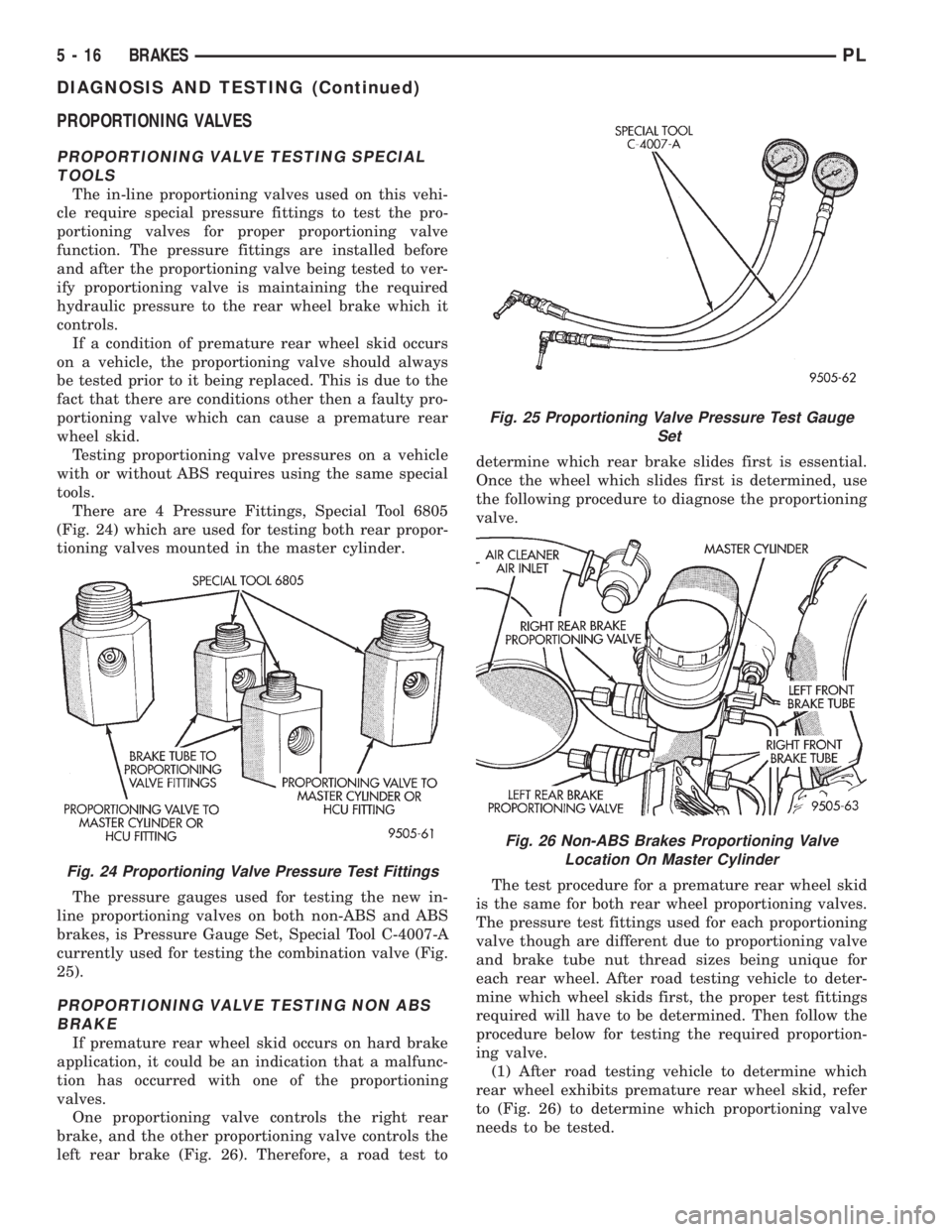
There are 4 Pressure Fittings, Special Tool 6805
(Fig. 24) which are used for testing both rear propor-
tioning valves mounted in the master cylinder.
The pressure gauges used for testing the new in-
line proportioning valves on both non-ABS and ABS
brakes, is Pressure Gauge Set, Special Tool C-4007-A
currently used for testing the combination valve (Fig.
25).
PROPORTIONING VALVE TESTING NON ABS
BRAKE
If premature rear wheel skid occurs on hard brake
application, it could be an indication that a malfunc-
tion has occurred with one of the proportioning
valves.
One proportioning valve controls the right rear
brake, and the other proportioning valve controls the
left rear brake (Fig. 26). Therefore, a road test todetermine which rear brake slides first is essential.
Once the wheel which slides first is determined, use
the following procedure to diagnose the proportioning
valve.
The test procedure for a premature rear wheel skid
is the same for both rear wheel proportioning valves.
The pressure test fittings used for each proportioning
valve though are different due to proportioning valve
and brake tube nut thread sizes being unique for
each rear wheel. After road testing vehicle to deter-
mine which wheel skids first, the proper test fittings
required will have to be determined. Then follow the
procedure below for testing the required proportion-
ing valve.
(1) After road testing vehicle to determine which
rear wheel exhibits premature rear wheel skid, refer
to (Fig. 26) to determine which proportioning valve
needs to be tested.
Fig. 24 Proportioning Valve Pressure Test Fittings
Fig. 25 Proportioning Valve Pressure Test Gauge
Set
Fig. 26 Non-ABS Brakes Proportioning Valve
Location On Master Cylinder
5 - 16 BRAKESPL
DIAGNOSIS AND TESTING (Continued)
Page 98 of 1200
(2) Remove hydraulic brake tube (Fig. 26) from
proportioning valve controlling the rear wheel of the
vehicle which has premature wheel skid.
(3) Remove proportioning valve from that outlet
port of the master cylinder.
CAUTION: Be sure the pressure test fitting being
installed into master cylinder, has the correct
thread sizes for installation into the master cylinder
and the installation of the proportioning valve.
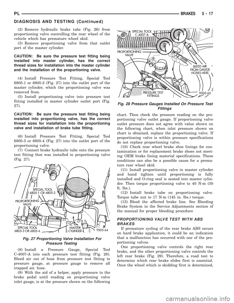
(4) Install Pressure Test Fitting, Special Tool
6805-1 or 6805-2 (Fig. 27) into the outlet port of the
master cylinder, which the proportioning valve was
removed from.
(5) Install proportioning valve into pressure test
fitting installed in master cylinder outlet port (Fig.
27).
CAUTION: Be sure the pressure test fitting being
installed into proportioning valve, has the correct
thread sizes for installation into the proportioning
valve and installation of brake tube fitting.
(6) Install Pressure Test Fitting, Special Tool
6805-3 or 6805-4 (Fig. 27) into the outlet port of the
proportioning valve.
(7) Connect brake hydraulic tube onto the pressure
test fitting that was installed in proportioning valve
(Fig. 27).
(8) Install a Pressure Gauge, Special Tool
C-4007-A into each pressure test fitting (Fig. 28).
Bleed air out of hose from pressure test fitting to
pressure gauge, at pressure gauge to remove all
trapped air. hose.
(9) With the aid of a helper, apply pressure to the
brake pedal until reading on proportioning valve
inlet gauge, is at the pressure shown on the followingchart. Then check the pressure reading on the pro-
portioning valve outlet gauge. If proportioning valve
outlet pressure does not agree with value shown on
the following chart, when inlet pressure shown on
chart is obtained, replace the proportioning valve. If
proportioning valve is within pressure specifications
do not replace proportioning valve.
(10) Check rear wheel brake shoe linings for con-
tamination or for replacement brake shoes not meet-
ing OEM brake lining material specifications. These
conditions can also be a possible cause for a prema-
ture rear wheel skid.
(11) Install proportioning valve in master cylinder
and hand tighten until proportioning is fully
installed and O-ring seal is seated into master cylin-
der. Then torque proportioning valve to 40 N´m (30
ft. lbs.).
(12) Install brake tube on proportioning valve.
Torque tube nut to 17 N´m (145 in. lbs.) torque.
(13) Bleed the affected brake line. See Bleeding
Brake System in the Service Adjustments section of
the manual for proper bleeding procedure
PROPORTIONING VALVE TEST WITH ABS
BRAKES
If premature cycling of the rear brake ABS occurs
on hard brake application, it could be an indication
that a malfunction has occurred with one of the pro-
portioning valves.
One proportioning valve controls the right rear
brake, and the other proportioning valve controls the
left rear brake (Fig. 29). Therefore, a road test to
determine which rear brake slides first is essential.
Once the wheel which is skidding first is determined,
Fig. 27 Proportioning Valve Installation For
Pressure Testing
Fig. 28 Pressure Gauges Installed On Pressure Test
Fittings
PLBRAKES 5 - 17
DIAGNOSIS AND TESTING (Continued)
Page 100 of 1200
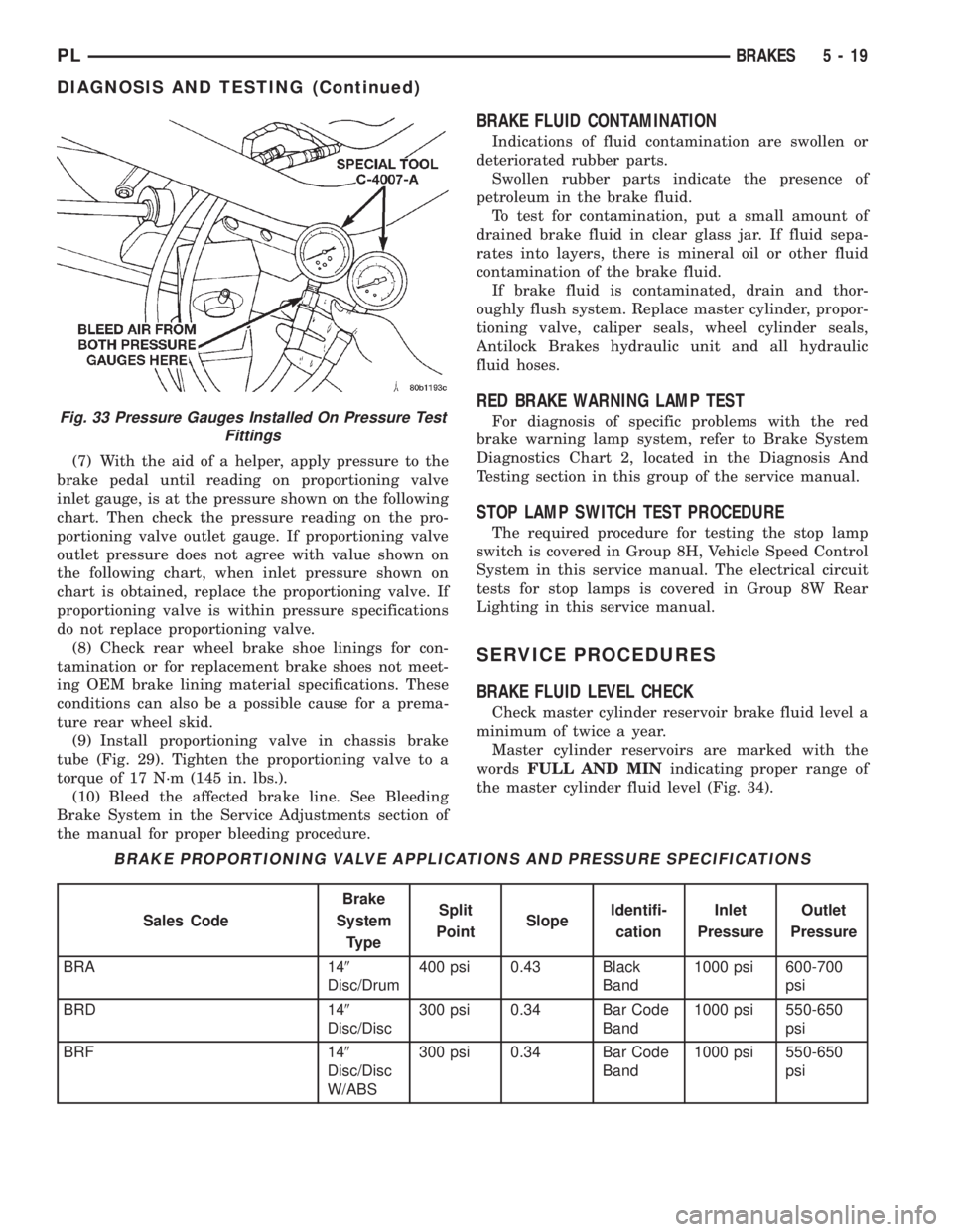
(7) With the aid of a helper, apply pressure to the
brake pedal until reading on proportioning valve
inlet gauge, is at the pressure shown on the following
chart. Then check the pressure reading on the pro-
portioning valve outlet gauge. If proportioning valve
outlet pressure does not agree with value shown on
the following chart, when inlet pressure shown on
chart is obtained, replace the proportioning valve. If
proportioning valve is within pressure specifications
do not replace proportioning valve.
(8) Check rear wheel brake shoe linings for con-
tamination or for replacement brake shoes not meet-
ing OEM brake lining material specifications. These
conditions can also be a possible cause for a prema-
ture rear wheel skid.
(9) Install proportioning valve in chassis brake
tube (Fig. 29). Tighten the proportioning valve to a
torque of 17 N´m (145 in. lbs.).
(10) Bleed the affected brake line. See Bleeding
Brake System in the Service Adjustments section of
the manual for proper bleeding procedure.
BRAKE FLUID CONTAMINATION
Indications of fluid contamination are swollen or
deteriorated rubber parts.
Swollen rubber parts indicate the presence of
petroleum in the brake fluid.
To test for contamination, put a small amount of
drained brake fluid in clear glass jar. If fluid sepa-
rates into layers, there is mineral oil or other fluid
contamination of the brake fluid.
If brake fluid is contaminated, drain and thor-
oughly flush system. Replace master cylinder, propor-
tioning valve, caliper seals, wheel cylinder seals,
Antilock Brakes hydraulic unit and all hydraulic
fluid hoses.
RED BRAKE WARNING LAMP TEST
For diagnosis of specific problems with the red
brake warning lamp system, refer to Brake System
Diagnostics Chart 2, located in the Diagnosis And
Testing section in this group of the service manual.
STOP LAMP SWITCH TEST PROCEDURE
The required procedure for testing the stop lamp
switch is covered in Group 8H, Vehicle Speed Control
System in this service manual. The electrical circuit
tests for stop lamps is covered in Group 8W Rear
Lighting in this service manual.
SERVICE PROCEDURES
BRAKE FLUID LEVEL CHECK
Check master cylinder reservoir brake fluid level a
minimum of twice a year.
Master cylinder reservoirs are marked with the
wordsFULL AND MINindicating proper range of
the master cylinder fluid level (Fig. 34).
Fig. 33 Pressure Gauges Installed On Pressure Test
Fittings
BRAKE PROPORTIONING VALVE APPLICATIONS AND PRESSURE SPECIFICATIONS
Sales CodeBrake
System
TypeSplit
PointSlopeIdentifi-
cationInlet
PressureOutlet
Pressure
BRA 149
Disc/Drum400 psi 0.43 Black
Band1000 psi 600-700
psi
BRD 149
Disc/Disc300 psi 0.34 Bar Code
Band1000 psi 550-650
psi
BRF 149
Disc/Disc
W/ABS300 psi 0.34 Bar Code
Band1000 psi 550-650
psi
PLBRAKES 5 - 19
DIAGNOSIS AND TESTING (Continued)
Page 101 of 1200
CAUTION: Use only MoparTbrake fluid or an
equivalent from a tightly sealed container. Brake
fluid must conform to DOT 3 specifications. Do not
use petroleum-based fluid because seal damage in
the brake system will result.
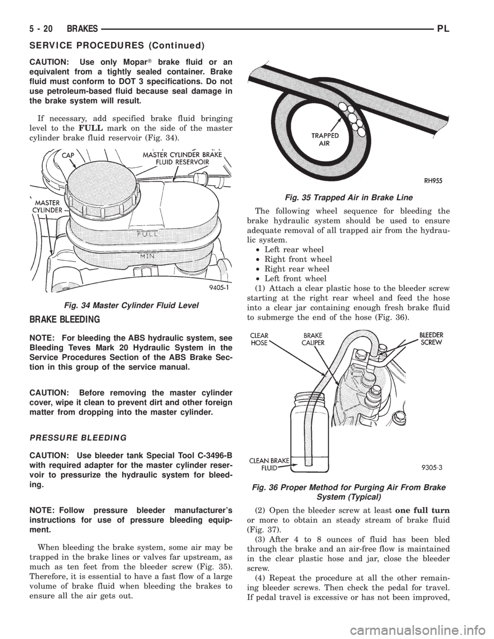
If necessary, add specified brake fluid bringing
level to theFULLmark on the side of the master
cylinder brake fluid reservoir (Fig. 34).
BRAKE BLEEDING
NOTE: For bleeding the ABS hydraulic system, see
Bleeding Teves Mark 20 Hydraulic System in the
Service Procedures Section of the ABS Brake Sec-
tion in this group of the service manual.
CAUTION: Before removing the master cylinder
cover, wipe it clean to prevent dirt and other foreign
matter from dropping into the master cylinder.
PRESSURE BLEEDING
CAUTION: Use bleeder tank Special Tool C-3496-B
with required adapter for the master cylinder reser-
voir to pressurize the hydraulic system for bleed-
ing.
NOTE: Follow pressure bleeder manufacturer's
instructions for use of pressure bleeding equip-
ment.
When bleeding the brake system, some air may be
trapped in the brake lines or valves far upstream, as
much as ten feet from the bleeder screw (Fig. 35).
Therefore, it is essential to have a fast flow of a large
volume of brake fluid when bleeding the brakes to
ensure all the air gets out.The following wheel sequence for bleeding the
brake hydraulic system should be used to ensure
adequate removal of all trapped air from the hydrau-
lic system.
²Left rear wheel
²Right front wheel
²Right rear wheel
²Left front wheel
(1) Attach a clear plastic hose to the bleeder screw
starting at the right rear wheel and feed the hose
into a clear jar containing enough fresh brake fluid
to submerge the end of the hose (Fig. 36).
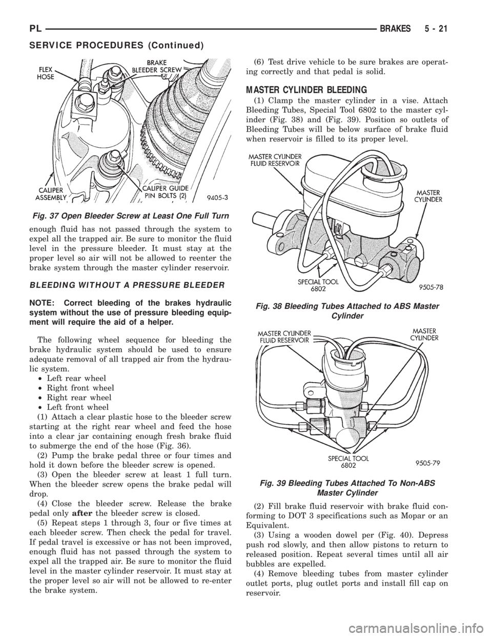
(2) Open the bleeder screw at leastone full turn
or more to obtain an steady stream of brake fluid
(Fig. 37).
(3) After 4 to 8 ounces of fluid has been bled
through the brake and an air-free flow is maintained
in the clear plastic hose and jar, close the bleeder
screw.
(4) Repeat the procedure at all the other remain-
ing bleeder screws. Then check the pedal for travel.
If pedal travel is excessive or has not been improved,
Fig. 34 Master Cylinder Fluid Level
Fig. 35 Trapped Air in Brake Line
Fig. 36 Proper Method for Purging Air From Brake
System (Typical)
5 - 20 BRAKESPL
SERVICE PROCEDURES (Continued)
Page 102 of 1200
enough fluid has not passed through the system to
expel all the trapped air. Be sure to monitor the fluid
level in the pressure bleeder. It must stay at the
proper level so air will not be allowed to reenter the
brake system through the master cylinder reservoir.
BLEEDING WITHOUT A PRESSURE BLEEDER
NOTE: Correct bleeding of the brakes hydraulic
system without the use of pressure bleeding equip-
ment will require the aid of a helper.
The following wheel sequence for bleeding the
brake hydraulic system should be used to ensure
adequate removal of all trapped air from the hydrau-
lic system.
²Left rear wheel
²Right front wheel
²Right rear wheel
²Left front wheel
(1) Attach a clear plastic hose to the bleeder screw
starting at the right rear wheel and feed the hose
into a clear jar containing enough fresh brake fluid
to submerge the end of the hose (Fig. 36).
(2) Pump the brake pedal three or four times and
hold it down before the bleeder screw is opened.
(3) Open the bleeder screw at least 1 full turn.
When the bleeder screw opens the brake pedal will
drop.
(4) Close the bleeder screw. Release the brake
pedal onlyafterthe bleeder screw is closed.
(5) Repeat steps 1 through 3, four or five times at
each bleeder screw. Then check the pedal for travel.
If pedal travel is excessive or has not been improved,
enough fluid has not passed through the system to
expel all the trapped air. Be sure to monitor the fluid
level in the master cylinder reservoir. It must stay at
the proper level so air will not be allowed to re-enter
the brake system.(6) Test drive vehicle to be sure brakes are operat-
ing correctly and that pedal is solid.
MASTER CYLINDER BLEEDING
(1) Clamp the master cylinder in a vise. Attach
Bleeding Tubes, Special Tool 6802 to the master cyl-
inder (Fig. 38) and (Fig. 39). Position so outlets of
Bleeding Tubes will be below surface of brake fluid
when reservoir is filled to its proper level.
(2) Fill brake fluid reservoir with brake fluid con-
forming to DOT 3 specifications such as Mopar or an
Equivalent.
(3) Using a wooden dowel per (Fig. 40). Depress
push rod slowly, and then allow pistons to return to
released position. Repeat several times until all air
bubbles are expelled.
(4) Remove bleeding tubes from master cylinder
outlet ports, plug outlet ports and install fill cap on
reservoir.
Fig. 37 Open Bleeder Screw at Least One Full Turn
Fig. 38 Bleeding Tubes Attached to ABS Master
Cylinder
Fig. 39 Bleeding Tubes Attached To Non-ABS
Master Cylinder
PLBRAKES 5 - 21
SERVICE PROCEDURES (Continued)
Page 122 of 1200
MASTER CYLINDER
REMOVE
CAUTION: On ABS equipped vehicles, vacuum in
power booster must be pumped down before
removing master cylinder to prevent booster from
sucking in any contamination. This can be done
simply by pumping the brake pedal until a firm
pedal is achieved, with the ignition off.
(1) On ABS equipped vehicles, be sure engine is
not running, and pump the brake pedal until a firm
pedal is achieved (4-5 strokes).
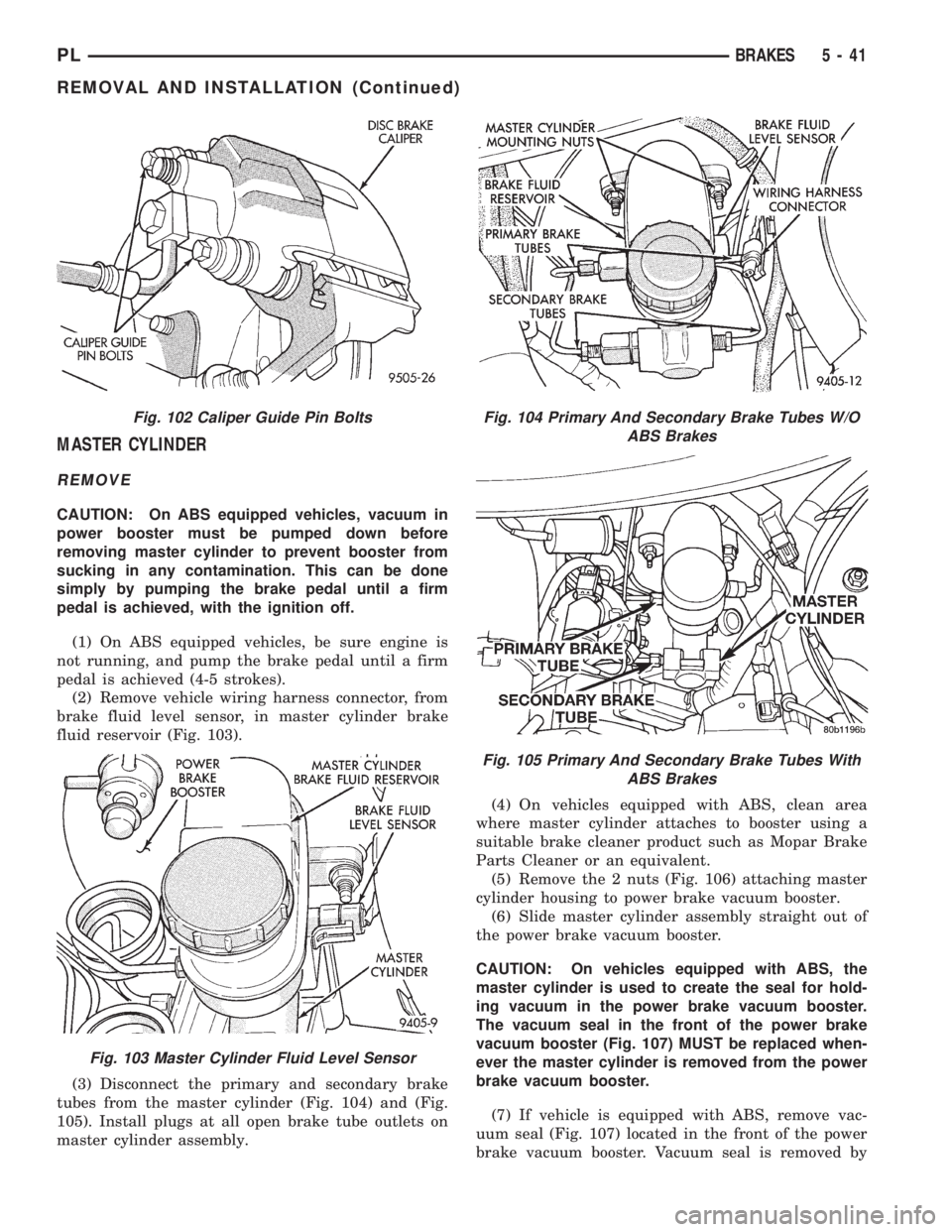
(2) Remove vehicle wiring harness connector, from
brake fluid level sensor, in master cylinder brake
fluid reservoir (Fig. 103).
(3) Disconnect the primary and secondary brake
tubes from the master cylinder (Fig. 104) and (Fig.
105). Install plugs at all open brake tube outlets on
master cylinder assembly.(4) On vehicles equipped with ABS, clean area
where master cylinder attaches to booster using a
suitable brake cleaner product such as Mopar Brake
Parts Cleaner or an equivalent.
(5) Remove the 2 nuts (Fig. 106) attaching master
cylinder housing to power brake vacuum booster.
(6) Slide master cylinder assembly straight out of
the power brake vacuum booster.
CAUTION: On vehicles equipped with ABS, the
master cylinder is used to create the seal for hold-
ing vacuum in the power brake vacuum booster.
The vacuum seal in the front of the power brake
vacuum booster (Fig. 107) MUST be replaced when-
ever the master cylinder is removed from the power
brake vacuum booster.
(7) If vehicle is equipped with ABS, remove vac-
uum seal (Fig. 107) located in the front of the power
brake vacuum booster. Vacuum seal is removed by
Fig. 102 Caliper Guide Pin Bolts
Fig. 103 Master Cylinder Fluid Level Sensor
Fig. 104 Primary And Secondary Brake Tubes W/O
ABS Brakes
Fig. 105 Primary And Secondary Brake Tubes With
ABS Brakes
PLBRAKES 5 - 41
REMOVAL AND INSTALLATION (Continued)
Page 123 of 1200
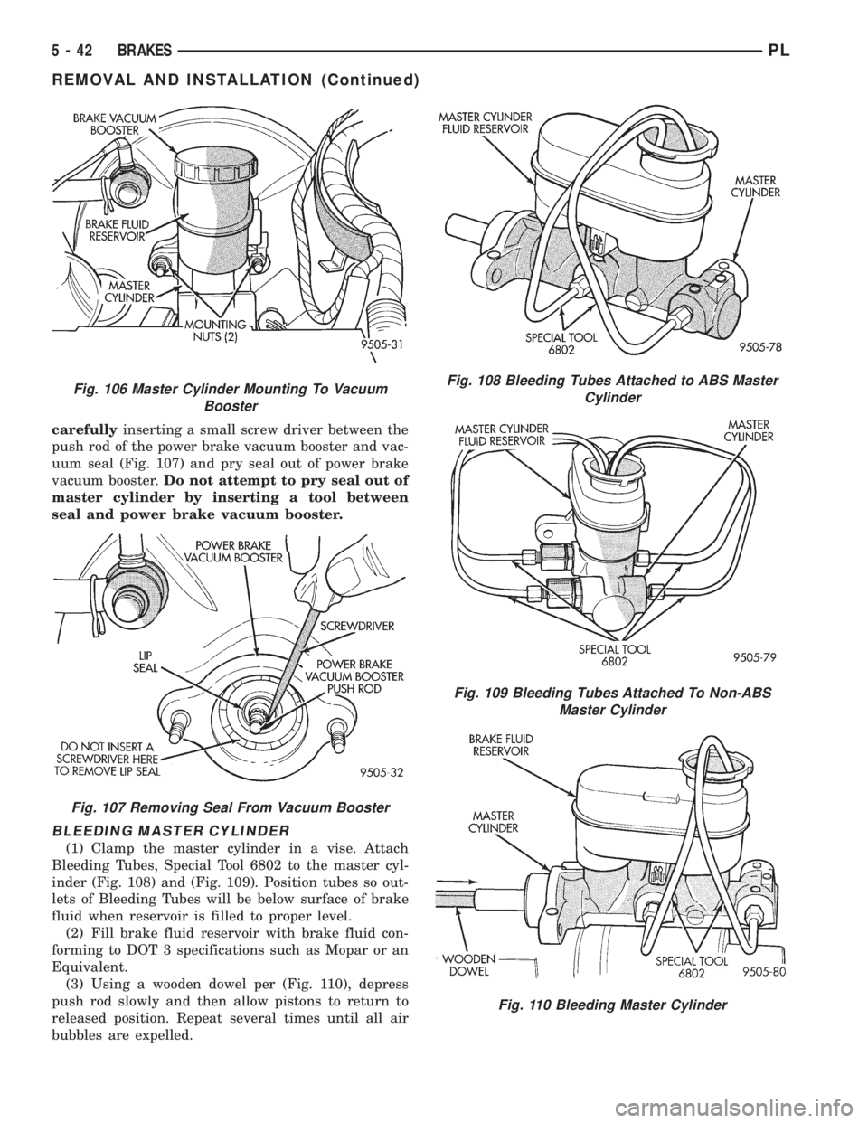
carefullyinserting a small screw driver between the
push rod of the power brake vacuum booster and vac-
uum seal (Fig. 107) and pry seal out of power brake
vacuum booster.Do not attempt to pry seal out of
master cylinder by inserting a tool between
seal and power brake vacuum booster.
BLEEDING MASTER CYLINDER
(1) Clamp the master cylinder in a vise. Attach
Bleeding Tubes, Special Tool 6802 to the master cyl-
inder (Fig. 108) and (Fig. 109). Position tubes so out-
lets of Bleeding Tubes will be below surface of brake
fluid when reservoir is filled to proper level.
(2) Fill brake fluid reservoir with brake fluid con-
forming to DOT 3 specifications such as Mopar or an
Equivalent.
(3) Using a wooden dowel per (Fig. 110), depress
push rod slowly and then allow pistons to return to
released position. Repeat several times until all air
bubbles are expelled.
Fig. 106 Master Cylinder Mounting To Vacuum
Booster
Fig. 107 Removing Seal From Vacuum Booster
Fig. 108 Bleeding Tubes Attached to ABS Master
Cylinder
Fig. 109 Bleeding Tubes Attached To Non-ABS
Master Cylinder
Fig. 110 Bleeding Master Cylinder
5 - 42 BRAKESPL
REMOVAL AND INSTALLATION (Continued)
Page 124 of 1200
(4) Remove bleeding tubes from master cylinder
outlet ports, plug outlet ports and install fill cap on
reservoir.
(5) Remove master cylinder from vise.
NOTE: Note: It is not necessary to bleed the entire
hydraulic system after replacing the master cylin-
der. But the master cylinder must have been bled
and filled upon installation.
INSTALL
CAUTION: When replacing the master cylinder on
a vehicle equipped with ABS, a NEW vacuum seal
MUST be installed in the power brake vacuum
booster. Use only the procedure detailed below for
installing vacuum seal into power brake vacuum
booster. Be sure old vacuum seal is removed from
power brake vacuum booster before attempting to
install new seal.
CAUTION: When lubricating master cylinder push
rod, use only Mopar Silicone Dielectric Compound.
Using any other type of grease or lubricant on the
push rod, will not provide adequate long term lubri-
cation of the push rod.
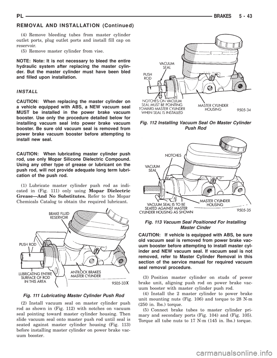
(1) Lubricate master cylinder push rod as indi-
cated in (Fig. 111) only usingMopar Dielectric
GreaseÐAnd No Substitutes.Refer to the Mopar
Chemicals Catalog to obtain the required lubricant.
(2) Install vacuum seal on master cylinder push
rod as shown in (Fig. 112) with notches on vacuum
seal pointing toward master cylinder housing. Then
slide vacuum seal onto master push rod until seal is
seated against master cylinder housing (Fig. 113)
before installing master cylinder on power brake vac-
uum booster.CAUTION: If vehicle is equipped with ABS, be sure
old vacuum seal is removed from power brake vac-
uum booster before attempting to install master cyl-
inder and NEW vacuum seal. If vacuum seal is not
removed, refer to Master Cylinder Removal in this
section of the service manual for required vacuum
seal removal procedure.
(3) Position master cylinder on studs of power
brake unit, aligning push rod on power brake vac-
uum booster with master cylinder push rod.
(4) Install the 2 master cylinder to power brake
unit mounting nuts (Fig. 106) and torque to 28 N´m
(250 in. lbs.) torque.
(5) Connect brake tubes to master cylinder pri-
mary and secondary ports (Fig. 104) and (Fig. 105).
Torque all tube nuts to 17 N´m (145 in. lbs.) torque.
Fig. 111 Lubricating Master Cylinder Push Rod
Fig. 112 Installing Vacuum Seal On Master Cylinder
Push Rod
Fig. 113 Vacuum Seal Positioned For Installing
Master Cinder
PLBRAKES 5 - 43
REMOVAL AND INSTALLATION (Continued)