1999 DODGE NEON engine oil capacity
[x] Cancel search: engine oil capacityPage 3 of 1200
ENGINE OIL
SAE VISCOSITY RATING INDICATES ENGINE OIL VISCOSITY
An SAE viscosity grade is used to specify the vis-
cosity of engine oil. SAE 30 specifies a single viscos-
ity engine oil. Engine oils also have multiple
viscosities. These are specified with a dual SAE vis-
cosity grade which indicates the cold-to-hot tempera-
ture viscosity range.
²SAE 30 = single grade engine oil.
²SAE 10W-30 = multiple grade engine oil.
API QUALITY CLASSIFICATION
The API Service Grade specifies the type of perfor-
mance the engine oil is intended to provide. The API
Service Grade specifications also apply to energy con-
serving engine oils.
Use engine oils that are API Service Certified.
5W-30 and 10W-30 MOPAR engine oils conform to
specifications.
Refer to Group 9, Engine for engine oil specifica-
tion.
GEAR LUBRICANTS
SAE ratings also apply to multiple grade gear
lubricants. In addition, API classification defines the
lubricants usage.
LUBRICANTS AND GREASES
Lubricating grease is rated for quality and usage
by the NLGI. All approved products have the NLGI
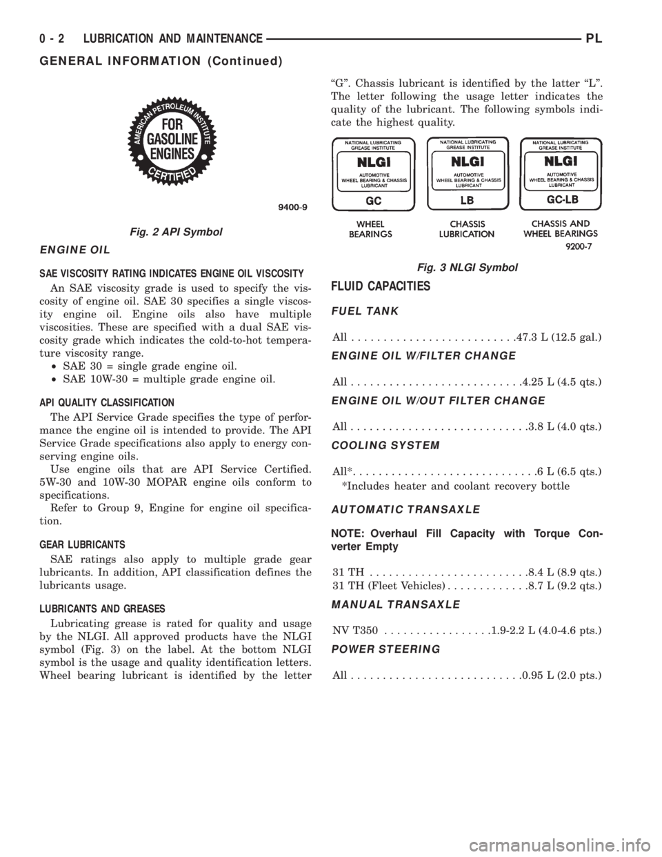
symbol (Fig. 3) on the label. At the bottom NLGI
symbol is the usage and quality identification letters.
Wheel bearing lubricant is identified by the letterªGº. Chassis lubricant is identified by the latter ªLº.
The letter following the usage letter indicates the
quality of the lubricant. The following symbols indi-
cate the highest quality.
FLUID CAPACITIES
FUEL TANK
All ..........................47.3 L (12.5 gal.)
ENGINE OIL W/FILTER CHANGE
All...........................4.25 L (4.5 qts.)
ENGINE OIL W/OUT FILTER CHANGE
All............................3.8 L (4.0 qts.)
COOLING SYSTEM
All*.............................6L(6.5 qts.)
*Includes heater and coolant recovery bottle
AUTOMATIC TRANSAXLE
NOTE: Overhaul Fill Capacity with Torque Con-
verter Empty
31TH .........................8.4 L (8.9 qts.)
31 TH (Fleet Vehicles).............8.7 L (9.2 qts.)
MANUAL TRANSAXLE
NV T350.................1.9-2.2 L (4.0-4.6 pts.)
POWER STEERING
All...........................0.95 L (2.0 pts.)
Fig. 2 API Symbol
Fig. 3 NLGI Symbol
0 - 2 LUBRICATION AND MAINTENANCEPL
GENERAL INFORMATION (Continued)
Page 194 of 1200
COOLING
CONTENTS
page page
GENERAL INFORMATION
ACCESSORY DRIVE BELTS................ 2
AUTOMATIC TRANSMISSION OIL COOLER.... 3
COOLANT RECOVERY SYSTEM (CRS)....... 2
COOLANT.............................. 3
COOLING SYSTEM PRESSURE CAP......... 3
COOLING SYSTEM....................... 1
ENGINE BLOCK HEATER.................. 3
ENGINE THERMOSTAT.................... 3
RADIATOR............................. 3
WATER PUMP.......................... 3
DESCRIPTION AND OPERATION
COOLANT PERFORMANCE................. 4
COOLING SYSTEM PRESSURE CAP......... 5
ENGINE BLOCK HEATER.................. 5
ENGINE THERMOSTAT.................... 4
RADIATOR HOSES AND CLAMPS........... 5
WATER PUMP.......................... 6
DIAGNOSIS AND TESTING
ACCESSORY DRIVEBELT DIAGNOSIS....... 13
COOLING SYSTEM DIAGNOSIS............. 7
COOLING SYSTEM FLOW CHECK.......... 14
DEAERATION.......................... 15
ELECTRIC FAN MOTOR TEST.............. 14
ENGINE THERMOSTAT TESTING........... 13
LOW COOLANT LEVEL AERATION.......... 15
PRESSURE CAP TO FILLER NECK SEAL
PRESSURE RELIEF CHECK.............. 15
PRESSURE TESTING COOLING SYSTEM
PRESSURE CAP...................... 15
RADIATOR FAN CONTROL................ 14
TEMPERATURE GAUGE INDICATION........ 16
TESTING COOLING SYSTEM FOR LEAKS.... 14WATER PUMP DIAGNOSIS............... 14
SERVICE PROCEDURES
COOLANT LEVEL CHECKÐROUTINE........ 16
COOLANT LEVELÐSERVICING............ 16
COOLANTÐADDING ADDITIONAL......... 16
COOLING SYSTEMÐDRAINING............ 16
COOLING SYSTEMÐREFILLING........... 17
REMOVAL AND INSTALLATION
ACCESSORY DRIVE BELTS............... 21
ENGINE BLOCK HEATER................. 21
ENGINE THERMOSTAT................... 18
RADIATOR DRAINCOCK.................. 20
RADIATOR FANS AND MOTOR............ 20
RADIATOR............................ 19
WATER PUMP INLET TUBE............... 18
WATER PUMP......................... 17
CLEANING AND INSPECTION
ACCESSORY DRIVE BELT INSPECTION...... 22
CHEMICAL CLEANING................... 23
CLEANING COOLING SYSTEM............. 22
COOLING SYSTEM CAP.................. 22
RADIATOR FLUSHING................... 23
REVERSE FLUSHING.................... 23
WATER PUMP......................... 21
ADJUSTMENTS
BELT TENSION GAUGE METHOD........... 24
PROPER BELT TENSION................. 23
SPECIFICATIONS
COOLING SYSTEM CAPACITY............. 24
TORQUE.............................. 24
SPECIAL TOOLS
COOLING............................. 24
GENERAL INFORMATION
COOLING SYSTEM
The cooling system consists of an engine cooling
module, thermostat, coolant, and a water pump to
circulate the coolant. The engine cooling module may
consist of a radiator, electric fan motor, fan, shroud,
coolant reserve system, transmission oil cooler, hoses,
clamps, air condition condenser and transmission oil lines.
²When the Engine is cold: The thermostat is
closed; the cooling system has no flow through the
radiator. The coolant flows through the engine,
heater system and bypass.
²When the Engine is warm: Thermostat is open;
the cooling system has flow through radiator, engine,
heater system and bypass.
Coolant flow circuit for the 2.0L engine is shown in
(Fig. 1).
PLCOOLING 7 - 1
Page 196 of 1200
ENGINE THERMOSTAT
The engine thermostat is located on the front of
the engine (radiator side) in the thermostat housing/
engine outlet connector. The thermostat has an air
bleed (vent) located in the flange and a O-ring for
sealing incorporate on it. There is a relief in the ther-
mostat housing/outlet connector for the O-ring.
WATER PUMP
The water pump has a diecast aluminum body and
housing with a stamped steel impeller. The water
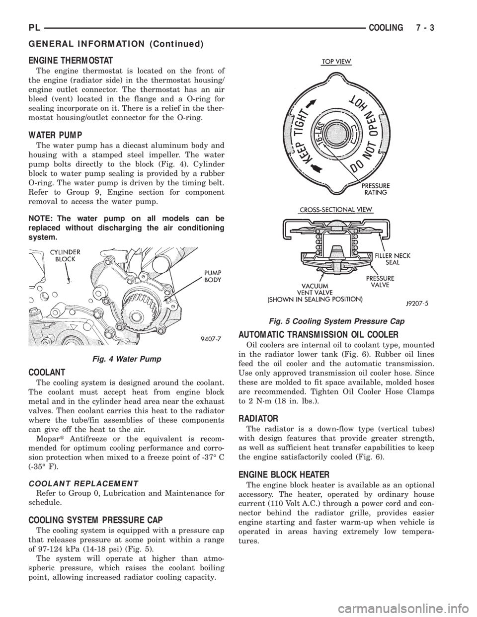
pump bolts directly to the block (Fig. 4). Cylinder
block to water pump sealing is provided by a rubber
O-ring. The water pump is driven by the timing belt.
Refer to Group 9, Engine section for component
removal to access the water pump.
NOTE: The water pump on all models can be
replaced without discharging the air conditioning
system.
COOLANT
The cooling system is designed around the coolant.
The coolant must accept heat from engine block
metal and in the cylinder head area near the exhaust
valves. Then coolant carries this heat to the radiator
where the tube/fin assemblies of these components
can give off the heat to the air.
MopartAntifreeze or the equivalent is recom-
mended for optimum cooling performance and corro-
sion protection when mixed to a freeze point of -37É C
(-35É F).
COOLANT REPLACEMENT
Refer to Group 0, Lubrication and Maintenance for
schedule.
COOLING SYSTEM PRESSURE CAP
The cooling system is equipped with a pressure cap
that releases pressure at some point within a range
of 97-124 kPa (14-18 psi) (Fig. 5).
The system will operate at higher than atmo-
spheric pressure, which raises the coolant boiling
point, allowing increased radiator cooling capacity.
AUTOMATIC TRANSMISSION OIL COOLER
Oil coolers are internal oil to coolant type, mounted
in the radiator lower tank (Fig. 6). Rubber oil lines
feed the oil cooler and the automatic transmission.
Use only approved transmission oil cooler hose. Since
these are molded to fit space available, molded hoses
are recommended. Tighten Oil Cooler Hose Clamps
to 2 N´m (18 in. lbs.).
RADIATOR
The radiator is a down-flow type (vertical tubes)
with design features that provide greater strength,
as well as sufficient heat transfer capabilities to keep
the engine satisfactorily cooled (Fig. 6).
ENGINE BLOCK HEATER
The engine block heater is available as an optional
accessory. The heater, operated by ordinary house
current (110 Volt A.C.) through a power cord and con-
nector behind the radiator grille, provides easier
engine starting and faster warm-up when vehicle is
operated in areas having extremely low tempera-
tures.
Fig. 4 Water Pump
Fig. 5 Cooling System Pressure Cap
PLCOOLING 7 - 3
GENERAL INFORMATION (Continued)
Page 198 of 1200
SELECTION AND ADDITIVES
The use of aluminum cylinder heads, intake mani-
folds DOHC, and water pumps requires special corro-
sion protection. MopartAntifreeze or the equivalent
is recommended for best engine cooling without cor-
rosion. When mixed only to a freeze point of -37ÉC
(-35ÉF) to -59ÉC (-50ÉF). If it looses color or becomes
contaminated, drain, flush, and replace with fresh
properly mixed solution.
COOLING SYSTEM PRESSURE CAP
The cooling system is equipped with a pressure cap
that releases built up pressure, maintaining a range
of 97-124 kPa (14-18 psi).
The cooling system will operate at higher than
atmospheric pressure. The higher pressure raises the
coolant boiling point thus, allowing increased radia-
tor cooling capacity.
There is a vent valve in the center of the cap that
allows a small coolant flow from the coolant reserve
system (CRS) tank. This valve is spring loaded in the
closed position. However it must be free to open dur-
ing system cool-down.If the valve is stuck shut,
the radiator hoses will collapse on cool-down.
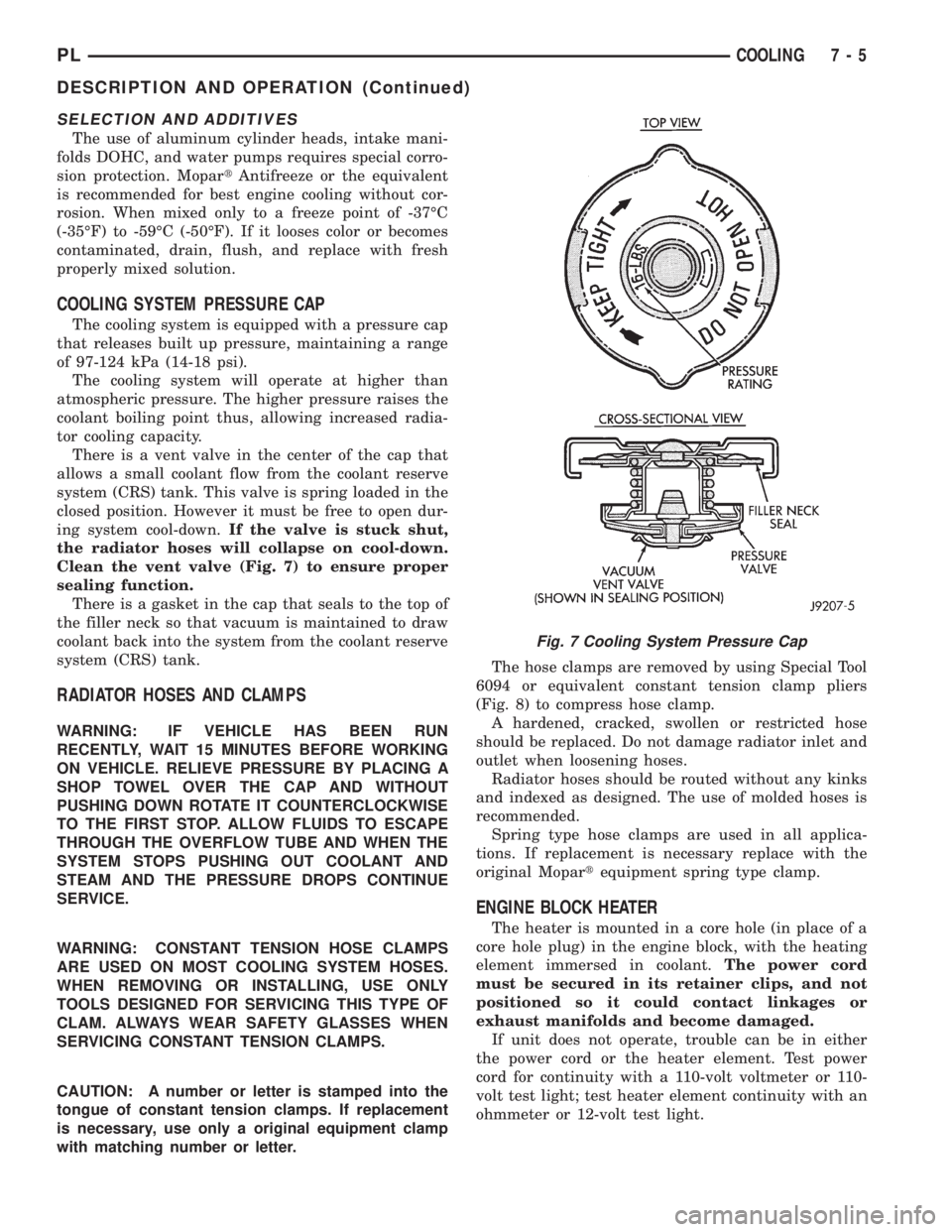
Clean the vent valve (Fig. 7) to ensure proper
sealing function.
There is a gasket in the cap that seals to the top of
the filler neck so that vacuum is maintained to draw
coolant back into the system from the coolant reserve
system (CRS) tank.
RADIATOR HOSES AND CLAMPS
WARNING: IF VEHICLE HAS BEEN RUN
RECENTLY, WAIT 15 MINUTES BEFORE WORKING
ON VEHICLE. RELIEVE PRESSURE BY PLACING A
SHOP TOWEL OVER THE CAP AND WITHOUT
PUSHING DOWN ROTATE IT COUNTERCLOCKWISE
TO THE FIRST STOP. ALLOW FLUIDS TO ESCAPE
THROUGH THE OVERFLOW TUBE AND WHEN THE
SYSTEM STOPS PUSHING OUT COOLANT AND
STEAM AND THE PRESSURE DROPS CONTINUE
SERVICE.
WARNING: CONSTANT TENSION HOSE CLAMPS
ARE USED ON MOST COOLING SYSTEM HOSES.
WHEN REMOVING OR INSTALLING, USE ONLY
TOOLS DESIGNED FOR SERVICING THIS TYPE OF
CLAM. ALWAYS WEAR SAFETY GLASSES WHEN
SERVICING CONSTANT TENSION CLAMPS.
CAUTION: A number or letter is stamped into the
tongue of constant tension clamps. If replacement
is necessary, use only a original equipment clamp
with matching number or letter.The hose clamps are removed by using Special Tool
6094 or equivalent constant tension clamp pliers
(Fig. 8) to compress hose clamp.
A hardened, cracked, swollen or restricted hose
should be replaced. Do not damage radiator inlet and
outlet when loosening hoses.
Radiator hoses should be routed without any kinks
and indexed as designed. The use of molded hoses is
recommended.
Spring type hose clamps are used in all applica-
tions. If replacement is necessary replace with the
original Mopartequipment spring type clamp.
ENGINE BLOCK HEATER
The heater is mounted in a core hole (in place of a
core hole plug) in the engine block, with the heating
element immersed in coolant.The power cord
must be secured in its retainer clips, and not
positioned so it could contact linkages or
exhaust manifolds and become damaged.
If unit does not operate, trouble can be in either
the power cord or the heater element. Test power
cord for continuity with a 110-volt voltmeter or 110-
volt test light; test heater element continuity with an
ohmmeter or 12-volt test light.
Fig. 7 Cooling System Pressure Cap
PLCOOLING 7 - 5
DESCRIPTION AND OPERATION (Continued)
Page 725 of 1200
2.0L SOHC ENGINE
INDEX
page page
DESCRIPTION AND OPERATION
ENGINE COMPONENTS.................. 14
ENGINE IDENTIFICATION................. 12
ENGINE LUBRICATION SYSTEM............ 13
GENERAL SPECIFICATION................ 12
DIAGNOSIS AND TESTING
CHECKING ENGINE OIL PRESSURE......... 14
SERVICE PROCEDURES
CRANKSHAFT END PLAY................. 16
CYLINDER BORE AND PISTON SIZING....... 14
FITTING CONNECTING RODS.............. 16
FITTING CRANKSHAFT BEARINGS.......... 16
FITTING PISTON RINGS.................. 16
REMOVAL AND INSTALLATION
CAMSHAFT OIL SEAL.................... 28
CAMSHAFT............................ 22
CRANKSHAFT DAMPER.................. 46
CRANKSHAFT OIL SEALÐFRONT........... 37
CRANKSHAFT OIL SEALÐREAR............ 38
CRANKSHAFT.......................... 39
CYLINDER HEAD COVER................. 21
CYLINDER HEAD........................ 25
ENGINE ASSEMBLY...................... 19
ENGINE MOUNTÐFRONT................. 18
ENGINE MOUNTÐLEFT................... 18
ENGINE MOUNTÐRIGHT................. 18
OIL FILTER ADAPTER.................... 42OILFILTER ............................ 42
OILPAN ............................... 36
OIL PUMP............................. 42
PISTON AND CONNECTING ROD........... 44
POWER HOP DAMPER................... 18
ROCKER ARM/HYDRAULIC LASH ADJUSTER . . 23
SPARK PLUG TUBE...................... 21
STRUCTURAL COLLARÐ2.0L.............. 19
TIMING BELT COVER.................... 27
TIMING BELT TENSIONERÐMECHANICAL.... 36
TIMING BELTÐWITH HYDRAULIC TENSIONER . 28
TIMING BELTÐWITH MECHANICAL
TENSIONER.......................... 33
VALVE SEALS AND SPRINGS IN VEHICLE.... 24
DISASSEMBLY AND ASSEMBLY
OIL PUMP............................. 47
VALVE SERVICE WITH THE CYLINDER HEAD
REMOVED........................... 47
CLEANING AND INSPECTION
CYLINDER BLOCK AND BORE............. 51
CYLINDER HEAD AND CAMSHAFT JOURNALS . 50
OIL PUMP............................. 50
SPECIFICATIONS
2.0L SOHC............................. 52
TORQUE CHART 2.0L SOHC............... 54
SPECIAL TOOLS
2.0L SOHC............................. 55
DESCRIPTION AND OPERATION
ENGINE IDENTIFICATION
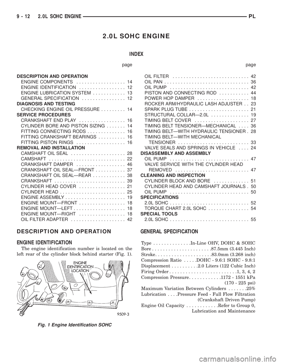
The engine identification number is located on the
left rear of the cylinder block behind starter (Fig. 1).
GENERAL SPECIFICATION
Type ..............In-Line OHV, DOHC & SOHC
Bore......................87.5mm (3.445 Inch)
Stroke.....................83.0mm (3.268 inch)
Compression Ratio.....DOHC - 9.6:1 SOHC - 9.8:1
Displacement..........2.0 Liters (122 Cubic Inch)
Firing Order.........................1,3,4,2
Compression Pressure............1172-1551 kPa
(170 - 225 psi)
Maximum Variation Between Cylinders.......25%
Lubrication. . . .Pressure Feed - Full Flow Filtration
(Crankshaft Driven Pump)
Engine Oil Capacity............Refer to Group 0,
Lubrication and Maintenance
Fig. 1 Engine Identification SOHC
9 - 12 2.0L SOHC ENGINEPL
Page 771 of 1200
2.0L DOHC ENGINE
INDEX
page page
DESCRIPTION AND OPERATION
ENGINE COMPONENTS.................. 59
ENGINE IDENTIFICATION NUMBER......... 58
ENGINE LUBRICATION SYSTEM............ 58
GENERAL SPECIFICATION................ 58
DIAGNOSIS AND TESTING
CHECKING ENGINE OIL PRESSURE......... 60
SERVICE PROCEDURES
CRANKSHAFT END PLAY................. 63
CYLINDER BORE AND PISTON SIZING....... 60
FITTING CONNECTING RODS.............. 62
FITTING CRANKSHAFT BEARINGS.......... 62
FITTING PISTON RINGS.................. 61
REMOVAL AND INSTALLATION
CAMSHAFT OIL SEALS................... 81
CAM FOLLOWER AND HYDRAULIC LASH
ADJUSTER ASSEMBLY.................. 69
CAMSHAFT............................ 67
CRANKSHAFT DAMPER.................. 73
CRANKSHAFT OIL SEALÐFRONT........... 82
CRANKSHAFT OIL SEALÐREAR............ 83
CRANKSHAFT.......................... 85
CYLINDER HEAD COVER................. 67
CYLINDER HEAD........................ 71
ENGINE ASSEMBLY...................... 65
ENGINE MOUNTÐFRONT................. 63
ENGINE MOUNTÐLEFT................... 63
ENGINE MOUNTÐRIGHT................. 64OIL FILTER ADAPTER.................... 87
OILFILTER ............................ 87
OILPAN ............................... 81
OIL PUMP............................. 88
PISTON AND CONNECTING ROD........... 89
POWER HOP DAMPER................... 64
STRUCTURAL COLLARÐ2.0L.............. 64
TIMING BELT COVER.................... 74
TIMING BELT TENSIONERÐMECHANICAL.... 80
TIMING BELTÐWITH HYDRAULIC TENSIONER . 75
TIMING BELTÐWITH MECHANICAL
TENSIONER.......................... 78
VALVE SPRING AND SEALSÐ
CYLINDER HEAD NOT REMOVED......... 69
DISASSEMBLY AND ASSEMBLY
OIL PUMP............................. 91
VALVE SERVICE WITH CYLINDER HEAD
REMOVED........................... 91
CLEANING AND INSPECTION
CYLINDER BLOCK AND BORE............. 96
CYLINDER HEAD AND CAMSHAFT JOURNALS . 94
OIL PUMP............................. 94
SPECIFICATIONS
2.0L DOHC............................. 96
TORQUE CHART 2.0L DOHC............... 98
SPECIAL TOOLS
2.0L DOHC............................. 98
DESCRIPTION AND OPERATION
ENGINE IDENTIFICATION NUMBER
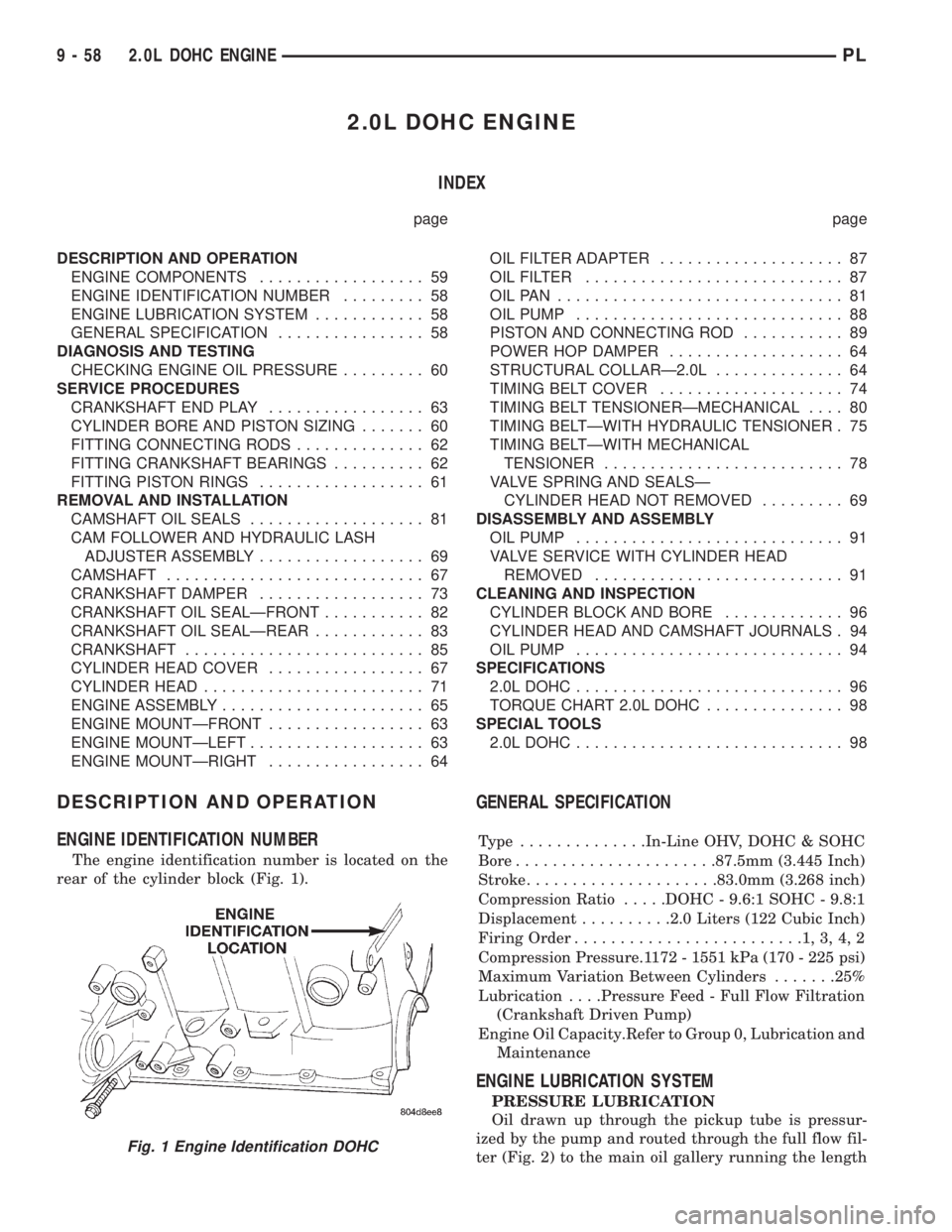
The engine identification number is located on the
rear of the cylinder block (Fig. 1).
GENERAL SPECIFICATION
Type ..............In-Line OHV, DOHC & SOHC
Bore......................87.5mm (3.445 Inch)
Stroke.....................83.0mm (3.268 inch)
Compression Ratio.....DOHC - 9.6:1 SOHC - 9.8:1
Displacement..........2.0 Liters (122 Cubic Inch)
Firing Order.........................1,3,4,2
Compression Pressure.1172 - 1551 kPa (170 - 225 psi)
Maximum Variation Between Cylinders.......25%
Lubrication. . . .Pressure Feed - Full Flow Filtration
(Crankshaft Driven Pump)
Engine Oil Capacity.Refer to Group 0, Lubrication and
Maintenance
ENGINE LUBRICATION SYSTEM
PRESSURE LUBRICATION
Oil drawn up through the pickup tube is pressur-
ized by the pump and routed through the full flow fil-
ter (Fig. 2) to the main oil gallery running the length
Fig. 1 Engine Identification DOHC
9 - 58 2.0L DOHC ENGINEPL
Page 860 of 1200
(6) From the engine compartment, pull the throttle
cable out of the dash panel grommet. The grommet
should remain in the dash panel.
INSTALLATION
(1) From the engine compartment, push the hous-
ing end fitting into the dash panel grommet.
(2) Install cable housing (throttle body end) into
the cable mounting bracket on the engine.
(3) From inside the vehicle, hold up pedal and feed
throttle cable core wire through hole in upper end of
the pedal shaft. Install cable retainer (Fig. 36).
(4) Install cable retainer clip.
(5) From the engine compartment, rotate the
throttle lever forward to the wide open position and
install cable clasp (Fig. 41).
(6) Install throttle control shield (Fig. 37). Tighten
to 5.6 N´m (50 in. lbs.).
SPECIFICATIONS
TORQUE
DESCRIPTION TORQUE
Accelerator Pedal to Dash Nuts...........12N´m
(105 in. lbs.)
Fuel Pump Module Locknut.....55N´m(40ft.lbs.)
Fuel Tank Strap Bolts.......22.5 N´m (200 in. lbs.)
Fuel Rail Bolts..............23N´m(195 in. lbs.)
Ignition Coil Mounting Bolts....11N´m(95in.lbs.)
Intake Manifold Bolts..........11N´m(95in.lbs.)
Throttle Control Shield........5.6 N´m (50 in. lbs.)
FUEL TANK CAPACITY
Vehicle Liters U.S. Gallons
PL 47 12.5
Nominal refill capacities are shown. A variation may be
observed from vehicle to vehicle due to manufacturing
tolerance and refill procedure.
PLFUEL SYSTEM 14 - 19
REMOVAL AND INSTALLATION (Continued)
Page 945 of 1200
CAUTION: The transaxle output shaft is serviced as
a unit. No disassembly and reassembly is possible.
Damage to the transaxle may result.
TRANSAXLE IDENTIFICATION INFORMATION
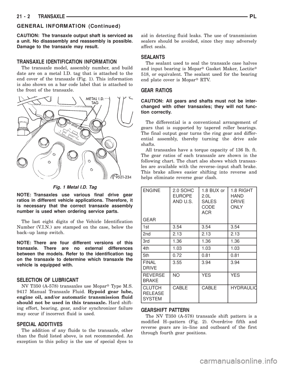
The transaxle model, assembly number, and build
date are on a metal I.D. tag that is attached to the
end cover of the transaxle (Fig. 1). This information
is also shown on a bar code label that is attached to
the front of the transaxle.
NOTE: Transaxles use various final drive gear
ratios in different vehicle applications. Therefore, it
is necessary that the correct transaxle assembly
number is used when ordering service parts.
The last eight digits of the Vehicle Identification
Number (V.I.N.) are stamped on the case, below the
back±up lamp switch.
NOTE: There are four different versions of this
transaxle. There are no external differences
between the models. Refer to the identification tag
on the transaxle to determine which transaxle the
vehicle is equipped with.
SELECTION OF LUBRICANT
NV T350 (A-578) transaxles use MopartType M.S.
9417 Manual Transaxle Fluid.Hypoid gear lube,
engine oil, and/or automatic transmission fluid
should not be used in this transaxle.Hard shift-
ing effort, bearing, gear, and/or synchronizer failure
may occur if incorrect fluid is used.
SPECIAL ADDITIVES
The addition of any fluids to the transaxle, other
than the fluid listed above, is not recommended. An
exception to this policy is the use of special dyes toaid in detecting fluid leaks. The use of transmission
sealers should be avoided, since they may adversely
affect seals.
SEALANTS
The sealant used to seal the transaxle case halves
and input bearing is MopartGasket Maker, Loctitet
518, or equivalent. The sealant used for the bearing
end plate cover is MopartRTV.
GEAR RATIOS
CAUTION: All gears and shafts must not be inter-
changed with other transaxles; they will not func-
tion correctly.
The differential is a conventional arrangement of
gears that is supported by tapered roller bearings.
The final output gear turns the ring gear and differ-
ential assembly, thereby turning the drive axle
shafts.
All transaxles have a torque capacity of 136 lb. ft.
The gear ratios of each transaxle are shown in the
following chart. The chart also shows which transax-
les are available with the reverse±input shaft brake.
This brake allows easier shifting into reverse and
helps eliminate reverse gear clash.
ENGINE 2.0 SOHC
EUROPE
AND U.S.1.8 BUX or
2.0L
SALES
CODE
ACR1.8 RIGHT
HAND
DRIVE
ONLY
GEAR
1st 3.54 3.54 3.54
2nd 2.13 2.13 2.13
3rd 1.36 1.36 1.36
4th 1.03 1.03 1.03
5th 0.72 0.81 0.81
FINAL
DRIVE3.55 3.94 3.94
REVERSE
BRAKENO YES YES
CLUTCH
RELEASE
SYSTEMCABLE CABLE HYDRAULIC
GEARSHIFT PATTERN
The NV T350 (A-578) transaxle shift pattern is a
modified H±pattern (Fig. 2). Overdrive fifth and
reverse gears are in±line and outboard of the first
through fourth gear positions.
Fig. 1 Metal I.D. Tag
21 - 2 TRANSAXLEPL
GENERAL INFORMATION (Continued)