Page 2438 of 3115

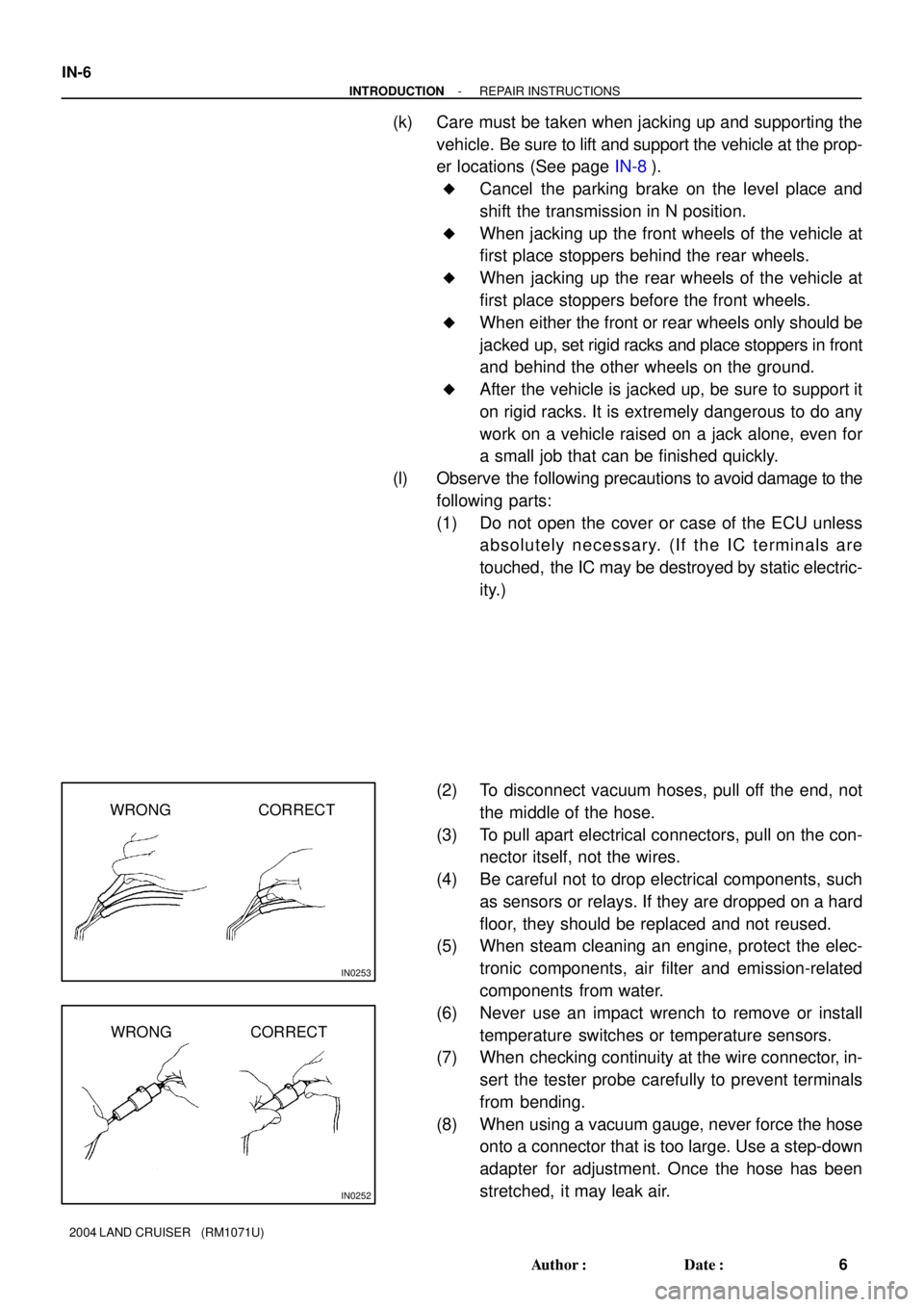
IN0253
WRONG CORRECT
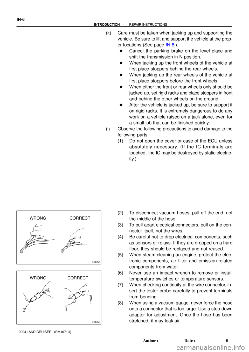
IN0252
WRONG CORRECT IN-6
- INTRODUCTIONREPAIR INSTRUCTIONS
6 Author�: Date�:
2004 LAND CRUISER (RM1071U)
(k) Care must be taken when jacking up and supporting the
vehicle. Be sure to lift and support the vehicle at the prop-
er locations (See page IN-8).
�Cancel the parking brake on the level place and
shift the transmission in N position.
�When jacking up the front wheels of the vehicle at
first place stoppers behind the rear wheels.
�When jacking up the rear wheels of the vehicle at
first place stoppers before the front wheels.
�When either the front or rear wheels only should be
jacked up, set rigid racks and place stoppers in front
and behind the other wheels on the ground.
�After the vehicle is jacked up, be sure to support it
on rigid racks. It is extremely dangerous to do any
work on a vehicle raised on a jack alone, even for
a small job that can be finished quickly.
(l) Observe the following precautions to avoid damage to the
following parts:
(1) Do not open the cover or case of the ECU unless
absolutely necessary. (If the IC terminals are
touched, the IC may be destroyed by static electric-
ity.)
(2) To disconnect vacuum hoses, pull off the end, not
the middle of the hose.
(3) To pull apart electrical connectors, pull on the con-
nector itself, not the wires.
(4) Be careful not to drop electrical components, such
as sensors or relays. If they are dropped on a hard
floor, they should be replaced and not reused.
(5) When steam cleaning an engine, protect the elec-
tronic components, air filter and emission-related
components from water.
(6) Never use an impact wrench to remove or install
temperature switches or temperature sensors.
(7) When checking continuity at the wire connector, in-
sert the tester probe carefully to prevent terminals
from bending.
(8) When using a vacuum gauge, never force the hose
onto a connector that is too large. Use a step-down
adapter for adjustment. Once the hose has been
stretched, it may leak air.
Page 2444 of 3115

IN0253
WRONG CORRECT
IN0252
WRONG CORRECT IN-6
- INTRODUCTIONREPAIR INSTRUCTIONS
6 Author�: Date�:
2004 LAND CRUISER (RM1071U)
(k) Care must be taken when jacking up and supporting the
vehicle. Be sure to lift and support the vehicle at the prop-
er locations (See page IN-8).
�Cancel the parking brake on the level place and
shift the transmission in N position.
�When jacking up the front wheels of the vehicle at
first place stoppers behind the rear wheels.
�When jacking up the rear wheels of the vehicle at
first place stoppers before the front wheels.
�When either the front or rear wheels only should be
jacked up, set rigid racks and place stoppers in front
and behind the other wheels on the ground.
�After the vehicle is jacked up, be sure to support it
on rigid racks. It is extremely dangerous to do any
work on a vehicle raised on a jack alone, even for
a small job that can be finished quickly.
(l) Observe the following precautions to avoid damage to the
following parts:
(1) Do not open the cover or case of the ECU unless
absolutely necessary. (If the IC terminals are
touched, the IC may be destroyed by static electric-
ity.)
(2) To disconnect vacuum hoses, pull off the end, not
the middle of the hose.
(3) To pull apart electrical connectors, pull on the con-
nector itself, not the wires.
(4) Be careful not to drop electrical components, such
as sensors or relays. If they are dropped on a hard
floor, they should be replaced and not reused.
(5) When steam cleaning an engine, protect the elec-
tronic components, air filter and emission-related
components from water.
(6) Never use an impact wrench to remove or install
temperature switches or temperature sensors.
(7) When checking continuity at the wire connector, in-
sert the tester probe carefully to prevent terminals
from bending.
(8) When using a vacuum gauge, never force the hose
onto a connector that is too large. Use a step-down
adapter for adjustment. Once the hose has been
stretched, it may leak air.
Page 2455 of 3115
LU08P-07
B04470
B04791
RH No.3 Timing Belt Cover
LH No.3 Timing Belt CoverNo.2 Timing Belt Cover
Camshaft Position
Sensor Connector
Engine Wire
Drive Belt Idler PulleyTiming Belt
Fan Bracket
N´m (kgf´cm, ft´lbf) : Specified torqueOil Cooler Pipe
Timing Belt Tensioner Dust Boot
Cover Plate
39 (400,29)
245 (2,500, 181)
32 (330, 24)
16 (160, 12)
7.5 (80, 66 in.´lbf)
16 (160, 12)
Water Bypass
Hose
LU-4
- LUBRICATIONOIL PUMP
1785 Author�: Date�:
2004 LAND CRUISER (RM1071U)
OIL PUMP
COMPONENTS
Page 2456 of 3115
B04472
GeneratorDrive Belt Tensioner
No.1 Timing Belt Cover
Crankshaft Pulley
Timing Belt
Timing Belt Guide
(Crankshaft Angle Sensor Plate)No.1 Idler Pulley
Crankshaft Timing PulleyPlate Washer
No.2 Idler Pulley
Timing Belt Cover SpacerGasket
� Precoated part
N´m (kgf´cm, ft´lbf) : Specified torque
39 (400, 29)
34.5 (350, 25)�
34.5 (350, 25)
- LUBRICATIONOIL PUMP
LU-5
1786 Author�: Date�:
2004 LAND CRUISER (RM1071U)
Page 2457 of 3115
B04485
Oil Pump
Crankshaft Position
Sensor Connector Crankshaft
Position Sensor
Oil Filter, Oil Cooler and
Filter Bracket AssemblyOil Cooler HoseClamp
Oil StrainerOil Dipstick
Guide and
Dipstick � O-Ring
� Gasket
No.1 Oil Pan
No.2 Oil Pan Oil Pan Baffle PlateClamp
� Gasket
Drain Plugx 20
N´m (kgf´cm, ft´lbf) : Specified torque
� Non-reusable part� Gasket
30.5 (310, 22)
15.5 (160, 11)
� O-Ring
15.5 (160, 11)
x 4
x 8
28 (290, 21)
7.5 (80, 66 in.´lbf)
7.5 (80, 66 in.´lbf)
7.5 (80, 66 in.´lbf)
7.5 (80, 66 in.´lbf)
39 (400, 29)
7.5 (80, 66 in.´lbf)
18 (185,13)
15 (153,11)
LU-6
- LUBRICATIONOIL PUMP
1787 Author�: Date�:
2004 LAND CRUISER (RM1071U)
Page 2464 of 3115

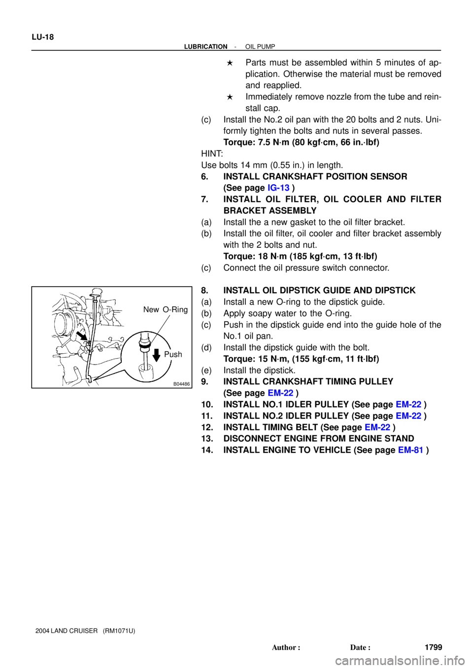
B04486
Push New O-Ring
LU-18
- LUBRICATIONOIL PUMP
1799 Author�: Date�:
2004 LAND CRUISER (RM1071U)
�Parts must be assembled within 5 minutes of ap-
plication. Otherwise the material must be removed
and reapplied.
�Immediately remove nozzle from the tube and rein-
stall cap.
(c) Install the No.2 oil pan with the 20 bolts and 2 nuts. Uni-
formly tighten the bolts and nuts in several passes.
Torque: 7.5 N´m (80 kgf´cm, 66 in.´lbf)
HINT:
Use bolts 14 mm (0.55 in.) in length.
6. INSTALL CRANKSHAFT POSITION SENSOR
(See page IG-13)
7. INSTALL OIL FILTER, OIL COOLER AND FILTER
BRACKET ASSEMBLY
(a) Install the a new gasket to the oil filter bracket.
(b) Install the oil filter, oil cooler and filter bracket assembly
with the 2 bolts and nut.
Torque: 18 N´m (185 kgf´cm, 13 ft´lbf)
(c) Connect the oil pressure switch connector.
8. INSTALL OIL DIPSTICK GUIDE AND DIPSTICK
(a) Install a new O-ring to the dipstick guide.
(b) Apply soapy water to the O-ring.
(c) Push in the dipstick guide end into the guide hole of the
No.1 oil pan.
(d) Install the dipstick guide with the bolt.
Torque: 15 N´m, (155 kgf´cm, 11 ft´lbf)
(e) Install the dipstick.
9. INSTALL CRANKSHAFT TIMING PULLEY
(See page EM-22)
10. INSTALL NO.1 IDLER PULLEY (See page EM-22)
11. INSTALL NO.2 IDLER PULLEY (See page EM-22)
12. INSTALL TIMING BELT (See page EM-22)
13. DISCONNECT ENGINE FROM ENGINE STAND
14. INSTALL ENGINE TO VEHICLE (See page EM-81)
Page 2466 of 3115

LU08Q-08
B04486
Pull O-Ring
B03736
B04629
SST SST
LU-8
- LUBRICATIONOIL PUMP
1789 Author�: Date�:
2004 LAND CRUISER (RM1071U)
REMOVAL
HINT:
When repairing the oil pump, the oil pan and strainer should be
removed and cleaned.
1. REMOVE ENGINE FROM VEHICLE
(See page EM-77)
2. INSTALL ENGINE TO ENGINE STAND FOR DIS-
ASSEMBLY
3. REMOVE TIMING BELT (See page EM-15)
4. REMOVE NO.1 IDLER PULLEY (See page EM-15)
5. REMOVE NO.2 IDLER PULLEY (See page EM-15)
6. REMOVE CRANKSHAFT TIMING PULLEY
(See page EM-15)
7. REMOVE OIL DIPSTICK AND GUIDE
(a) Remove the bolt holding the oil dipstick to the LH cylinder
head.
(b) Pull out the dipstick guide together with the dipstick from
the No.1 oil pan.
(c) Remove the O-ring from the dipstick guide.
8. REMOVE OIL FILTER, OIL COOLER AND FILTER
BRACKET ASSEMBLY
(a) Disconnect the oil pressure switch connector.
(b) Remove the 2 bolts, nut, and oil filter, oil cooler and filter
bracket assembly.
(c) Remove the gasket from the filter bracket.
9. REMOVE CRANKSHAFT POSITION SENSOR
(See page IG-12)
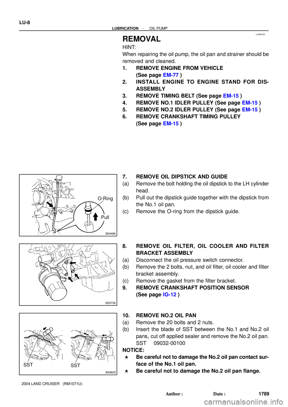
10. REMOVE NO.2 OIL PAN
(a) Remove the 20 bolts and 2 nuts.
(b) Insert the blade of SST between the No.1 and No.2 oil
pans, cut off applied sealer and remove the No.2 oil pan.
SST 09032-00100
NOTICE:
�Be careful not to damage the No.2 oil pan contact sur-
face of the No.1 oil pan.
�Be careful not to damage the No.2 oil pan flange.
Page 2543 of 3115
PP0U3-05
- PREPARATIONSFI
PP-9
68 Author�: Date�:
2004 LAND CRUISER (RM1071U)
SFI
SST (Special Service Tools)
09023-12700Union Nut Wrench 17mmFuel line flare nut
09268-41047Injection Measuring Tool Set
(09268-41091)NO.7 Union
(09268-41 110)Adaptor
(09268-41300)Clamp
09268-45014EFI Fuel Pressure Gauge
(09268-41 190)Adaptor
(90405-06167)I Union
09612-24014Steering Gear Housing Overhaul
Tool Set
(09617-2401 1)Steering Rack WrenchFuel pressure pulsation damper
09816-30010Oil Pressure Switch SocketKnock sensor
09842-30070Wiring ºFº EFI Inspection