Page 2377 of 3115
2004 LAND CRUISER (EWD548U)
370Air Conditioning (Rear)
MCool Warm
GND PT VZ MHOT MCOOL 3K 39
BW1 1
B- W
10A
ECU- IG2
3K 35 From Power Source System
(
See Page 94)
R- L
B- W
BW1 3A 7TER
Y Y
2 1
BW1 4
Y- G
R21
A 9SG1
BL1 7
BD3 2
B- W
Y- G
Y- G
BL4 7
BD3 16
GR - R
BL4 5
BD3 15
R- Y
BL4 4
BD3 14
Y
BL4 3
BD3 13
W- L
A 6TPH
A 5S51
A 12MHR
A 11MCR
351 2
R 9 2
GR- R
R- Y
Y
W- L GR - R
R- Y
Y
W- L Y- G Y- G
D
DD A
Y- GY- G Y- G
Y- G
IG1
Y- G A32(
A)
, A33(
B)
, A34(
C)
J224 A/C Amplifier (
Rear)
Rear Air Mix Control Servo Motor
Rear Evaporator Temp. Sensor
Junction
Connector
Junction
Connector J23(
B)
, J25(
A) (
*2) (
*1)
B CA C
A C(
*1)
B C(
*2) A C
B C
* 2 : w/o Navigation System * 1 : w/ Navigation System
Page 2378 of 3115
2004 LAND CRUISER (EWD548U)
371
1
2BL4 6
BD3 17
GR- G
A 8TINR
GR- G GR- G Y- G
R26
Y- G
LO- I AUTO-I ME-I HI-I FACE-I
HotFOOT- I
Cool
AUTO
FootLO
Middle
HI
Fa ce
Bi- Level
B/L- I S5 T- SET SGB 12SG2
2 1B 7TRR
B13B 8TESTR
20 21
B G- Y
G- Y
L- O G- Y
L- O
B 4S52
22
Y- R Y- R
C 5 AUTO- I
7
L- R L- R
C 6LO- I
6
L- W L- W
C 7ME- I
5
L L
C 18HI- I
4
L L
C 15FACE- I
3
G G
C 16B/L- I
2
W- G W- G
C 17FOOT- I
1
W- R W- R
A32(
A)
, A33(
B)
, A34(
C)
R 8
R34
A/C Amplifier (
Rear)
Rear A/C Control SW
Rear Inlet Air Temp. Sensor
Room Temp. Sensor (
Rear)
Page 2380 of 3115

2004 LAND CRUISER (EWD548U)
373
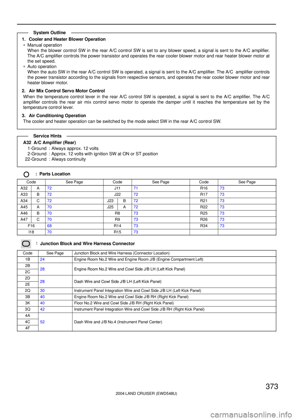
1. Cooler and Heater Blower Operation
*Manual operation
When the blower control SW in the rear A/C control SW is set to any blower speed, a signal is sent to the A/C amplifier.
The A/C amplifier controls the power transistor and operates the rear cooler blower motor and rear heater blower motor at
the set speed.
*Auto operation
When the auto SW in the rear A/C control SW is operated, a signal is sent to the A/C amplifier. The A/C amplifier controls
the power transistor according to the signals from respective sensors, and operates the rear cooler blower motor and rear
heater blower motor.
2. Air Mix Control Servo Motor Control
When the temperature control lever in the rear A/C control SW is operated, a signal is sent to the A/C amplifier. The A/C
amplifier controls the rear air mix control servo motor to operate the damper until it reaches the temperature set by the
temperature control lever.
3. Air Conditioning Operation
The cooler and heater operation can be switched by the mode select SW in the rear A/C control SW.
A32 A/C Amplifier (Rear)
1-Ground : Always approx. 12 volts
2-Ground : Approx. 12 volts with ignition SW at ON or ST position
22-Ground : Always continuity
: Parts Location
CodeSee PageCodeSee PageCodeSee Page
A32A72J1171R1673
A33B72J2272R1773
A34C72J23B72R2173
A45A70J25A72R2273
A46B70R873R2573
A47C70R973R2673
F1668R1473R3473
I1870R1573
:Junction Block and Wire Harness Connector
CodeSee PageJunction Block and Wire Harness (Connector Location)
1B24Engine Room No.2 Wire and Engine Room J/B (Engine Compartment Left)
2B28Engine Room No 2 Wire and Cowl Side J/B LH (Left Kick Panel)2C28Engine Room No.2 Wire and Cowl Side J/B LH (Left Kick Panel)
2D28Dash Wire and Cowl Side J/B LH (Left Kick Panel)2E28Dash Wire and Cowl Side J/B LH (Left Kick Panel)
2Q30Instrument Panel Integration Wire and Cowl Side J/B LH (Left Kick Panel)
3B40Engine Room No.2 Wire and Cowl Side J/B RH (Right Kick Panel)
3K40Floor No.2 Wire and Cowl Side J/B RH (Right Kick Panel)
3Q42Instrument Panel Integration Wire and Cowl Side J/B RH (Right Kick Panel)
4A
4C52Dash Wire and J/B No.4 (Instrument Panel Center)
4F
()
System Outline
Service Hints
Page 2389 of 3115
IG08T-03
B06326
V-Bank Cover
7.5 (80, 66 in.´lbf)
: Specified torqueN´m (kgf´cm, ft´lbf) Camshaft Position
Sensor Connector
Grommet
Engine Wire Camshaft Position Sensor
Oil Cooler Pipe
LH No.3 Timing Belt Cover
7.5 (80, 66 in.´lbf)
7.5 (80, 66 in.´lbf)
Fuel Return
Hose
IG-8
- IGNITIONCAMSHAFT POSITION SENSOR
1811 Author�: Date�:
2004 LAND CRUISER (RM1071U)
CAMSHAFT POSITION SENSOR
COMPONENTS
Page 2390 of 3115
IG08V-01
B04078
IG-10
- IGNITIONCAMSHAFT POSITION SENSOR
1813 Author�: Date�:
2004 LAND CRUISER (RM1071U)
INSTALLATION
1. INSTALL CAMSHAFT POSITION SENSOR
Install the camshaft position sensor with the bolt and stud bolt
Torque: 7.5 N´m (80 kgf´cm, 66 in.´lbf)
2. INSTALL LH NO.3 TIMING BELT COVER
(See page EM-22)
3. CONNECT RADIATOR HOSE
4. INSTALL V-BANK COVER
5. FILL ENGINE COOLANT (See page CO-2)
6. CHECK ENGINE COOLANT FOR LEAKS
7. CHECK IGNITION TIMING (See page EM-9)
Page 2391 of 3115
IG08U-01
B04078
- IGNITIONCAMSHAFT POSITION SENSOR
IG-9
1812 Author�: Date�:
2004 LAND CRUISER (RM1071U)
REMOVAL
1. REMOVE V-BANK COVER
2. DRAIN ENGINE COOLANT
3. DISCONNECT UPPER RADIATOR HOSE
4. REMOVE LH NO.3 TIMING BELT COVER
(See page EM-15)
5. REMOVE CAMSHAFT POSITION SENSOR
Remove the bolt, stud bolt and camshaft position sensor.
Page 2392 of 3115
IG08W-01
B03154N´m (kgf´cm, ft´lbf): Specified torque
Crankshaft Position Sensor
No.2 Engine Under CoverCrankshaft Position
Sensor Connector
6.5 (65, 58 in.´lbf)
x 8
- IGNITIONCRANKSHAFT POSITION SENSOR
IG-1 1
1814 Author�: Date�:
2004 LAND CRUISER (RM1071U)
CRANKSHAFT POSITION SENSOR
COMPONENTS
Page 2393 of 3115
IG08Y-01
- IGNITIONCRANKSHAFT POSITION SENSOR
IG-13
1816 Author�: Date�:
2004 LAND CRUISER (RM1071U)
INSTALLATION
Installation is in the reverse order of removal. (See page IG-12)