Page 2248 of 3115
2004 LAND CRUISER (EWD548U)
241
BM2 3
A 11
W- BG
W- BG
W- B GG G
C25(
A)
, C26(
B)
, C27(
C)
10 2G2K 18BU1 3 5BM2
BJ B11
BM BU1 1 4BM23
E 21
E
J22B 5
W- B W- B
W- BG
LBE+A 19(
*1)
(
*2)* 1 : w/ Side Airbag
* 2 : w/o Side Air bag
Buckle SW LH
Junction
Connector Center Airbag Sensor Assembly
DBKL 22 B
B
MPX2
(
*1)
2G 42Q 7 MPX13
T 7
Tilt and
Telescopic
ECU3D 41
B
MPX2 3F 73Q 37
BSB
SB G
GBody ECU B 7
13 23
Page 2249 of 3115

2004 LAND CRUISER (EWD548U)
242SRS
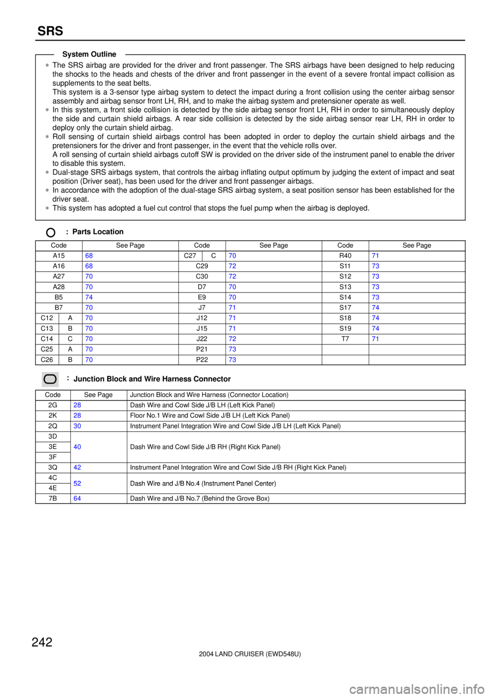
*The SRS airbag are provided for the driver and front passenger. The SRS airbags have been designed to help reducing
the shocks to the heads and chests of the driver and front passenger in the event of a severe frontal impact collision as
supplements to the seat belts.
This system is a 3-sensor type airbag system to detect the impact during a front collision using the center airbag sensor
assembly and airbag sensor front LH, RH, and to make the airbag system and pretensioner operate as well.
*In this system, a front side collision is detected by the side airbag sensor front LH, RH in order to simultaneously deploy
the side and curtain shield airbags. A rear side collision is detected by the side airbag sensor rear LH, RH in order to
deploy only the curtain shield airbag.
*Roll sensing of curtain shield airbags control has been adopted in order to deploy the curtain shield airbags and the
pretensioners for the driver and front passenger, in the event that the vehicle rolls over.
A roll sensing of curtain shield airbags cutoff SW is provided on the driver side of the instrument panel to enable the driver
to disable this system.
*Dual-stage SRS airbags system, that controls the airbag inflating output optimum by judging the extent of impact and seat
position (Driver seat), has been used for the driver and front passenger airbags.
*In accordance with the adoption of the dual-stage SRS airbag system, a seat position sensor has been established for the
driver seat.
*This system has adopted a fuel cut control that stops the fuel pump when the airbag is deployed.
: Parts Location
CodeSee PageCodeSee PageCodeSee Page
A1568C27C70R4071
A1668C2972S1173
A2770C3072S1273
A2870D770S1373
B574E970S1473
B770J771S1774
C12A70J1271S1874
C13B70J1571S1974
C14C70J2272T771
C25A70P2173
C26B70P2273
:Junction Block and Wire Harness Connector
CodeSee PageJunction Block and Wire Harness (Connector Location)
2G28Dash Wire and Cowl Side J/B LH (Left Kick Panel)
2K28Floor No.1 Wire and Cowl Side J/B LH (Left Kick Panel)
2Q30Instrument Panel Integration Wire and Cowl Side J/B LH (Left Kick Panel)
3D
3E40Dash Wire and Cowl Side J/B RH (Right Kick Panel)
3F
(g )
3Q42Instrument Panel Integration Wire and Cowl Side J/B RH (Right Kick Panel)
4C52Dash Wire and J/B No 4 (Instrument Panel Center)4E52Dash Wire and J/B No.4 (Instrument Panel Center)
7B64Dash Wire and J/B No.7 (Behind the Grove Box)
System Outline
Page 2260 of 3115
2004 LAND CRUISER (EWD548U)
253
E EIU3 15C 26
SB B
MPX3
J14 (
w/ Side Airbag)
2G 4
2Q 7 23 A
3Q 37
3F 73D41
22
MPX2
C263
MPX1
T 7
B
BSB B
MPX2
IF IG 416 GND1 GND2
T 531
SB B
IL3 1
B 816345DN UP LMT PLS SGND
E PLS LMT U P 14235
G
Y
L- Y
L- W
BR- BWW
P15A 11
IY2 11MPX4
20A
P/W
(
FR)
L
From Power Source System
(
See Page 94)
3I 2
8
MPX1 12
BDR 11
PCT
GND
7
W- B
SEL1
9
W- B
P18
II 3I 9
W- B W- BW
16345DN UP LMT PLS SGND
E PLS LMT U D 14235
G
Y
L- Y
L- W
BR- BWW
P16B 14
ID4 19
BA4 11MPX5
8
MPX1B 7(
A)
, B 8(
B)
, B 9(
C)
P19Y- B
Y- B
MPX1
Center Airbag
Sensor Assembly Power Window Motor Fr ont RH Power Window Motor Rear LHPower Window
Control SW
Front RH Power Window
Contr ol SW
Rear LH
Th eft
Deterr ent
ECU
Tilt and
Te le sco pic
ECU Body ECU
Junction
Connector
KSW
R- B R- B
C 14
23 3E 18 3E
1 2
U 1
Unlock
Warning SW
13P 33P
18 2E
W- BW- B
Page 2261 of 3115

2004 LAND CRUISER (EWD548U)
254Power Window
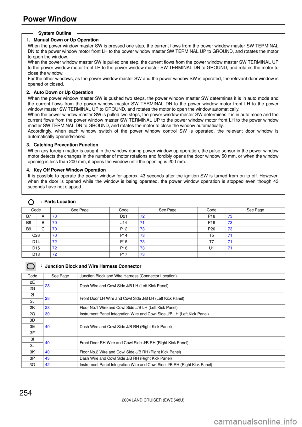
1. Manual Down or Up Operation
When the power window master SW is pressed one step, the current flows from the power window master SW TERMINAL
DN to the power window motor front LH to the power window master SW TERMINAL UP to GROUND, and rotates the motor
to open the window.
When the power window master SW is pulled one step, the current flows from the power window master SW TERMINAL UP
to the power window motor front LH to the power window master SW TERMINAL DN to GROUND, and rotates the motor to
close the window.
For the other windows, as the power window master SW and the power window SW is operated, the relevant door window is
opened or closed.
2. Auto Down or Up Operation
When the power window master SW is pushed two steps, the power window master SW determines it is in auto mode and
the current flows from the power window master SW TERMINAL DN to the power window motor front LH to the power
window master SW TERMINAL UP to GROUND, and rotates the motor to open the window automatically.
When the power window master SW is pulled two steps, the power window master SW determines it is in auto mode and the
current flows from the power window master SW TERMINAL UP to the power window motor front LH to the power window
master SW TERMINAL DN to GROUND, and rotates the motor to close the window automatically.
Accordingly, when each window switch of the power window control SW is operated, the relevant door window is
automatically opened/closed.
3. Catching Prevention Function
When any foreign matter is caught in the window during power window up operation, the pulse sensor in the power window
motor detects the changes in the number of motor rotations and forcibly opens the door window 50 mm, or when the window
opening is less than 200 mm, it opens the window until the opening is 200 mm.
4. Key Off Power Window Operation
It is possible to operate the power window for approx. 43 seconds after the ignition SW is turned from on to off. However,
when the door is opened while the window is being operated, the power window operation is stopped even though 43
seconds have not elapsed.
: Parts Location
CodeSee PageCodeSee PageCodeSee Page
B7A70D2172P1873
B8B70J1471P1973
B9C70P1273P2073
C2670P1473T571
D1472P1573T771
D1572P1673U171
D1872P1773
:Junction Block and Wire Harness Connector
CodeSee PageJunction Block and Wire Harness (Connector Location)
2E28Dash Wire and Cowl Side J/B LH (Left Kick Panel)2G28Dash Wire and Cowl Side J/B LH (Left Kick Panel)
2I28Front Door LH Wire and Cowl Side J/B LH (Left Kick Panel)2J28Front Door LH Wire and Cowl Side J/B LH (Left Kick Panel)
2K28Floor No.1 Wire and Cowl Side J/B LH (Left Kick Panel)
2Q30Instrument Panel Integration Wire and Cowl Side J/B LH (Left Kick Panel)
3D
3E40Dash Wire and Cowl Side J/B RH (Right Kick Panel)
3F
(g )
3I40Front Door RH Wire and Cowl Side J/B RH (Right Kick Panel)3J40Front Door RH Wire and Cowl Side J/B RH (Right Kick Panel)
3K40Floor No.2 Wire and Cowl Side J/B RH (Right Kick Panel)
3P43Dash Wire and Cowl Side J/B RH (Right Kick Panel)
3Q42Instrument Panel Integration Wire and Cowl Side J/B RH (Right Kick Panel)
System Outline
Page 2291 of 3115
2004 LAND CRUISER (EWD548U)
284Theft Deterrent
B 7(
A)
, B 8(
B)
, B 9(
C)
IL3 8
3Q 82
3B 4
EA2 6
2 1
EAIL3 7
63B 84 3Q
1
E 3
T 1
IL3 3
IU3 147. 5A
SECURITY From Power Source System
(
See Page 94)
3E 16 3Q 72 IL3 14
Z 1
L- W34 1 11 2DSWH SH- GBS +B1
L- B
W
Y- G
LG SB
SB
SB
SB
LG L- B
W
Y- G L- B W- B
T 5
LG
2 1
L- W B- W
Engine Hood Courtesy SW
Theft Deterrent Horn
Theft Deterrent ECU Body ECU
B- W
Option Connector
(
Glass Breakage Sensor)
Page 2306 of 3115
2004 LAND CRUISER (EWD548U)
299
A 6
II 3D 42 (
*1)
A AA
A
J 1
W- B
1B 1
4B 8
6B 2
5B 9
3B 12
8B 11
7B 10
(
*1) W W- B
G
R
B
B- W
B- R
B- Y
T 4 GND A2 B2 F/B2 COM2 S5V2 SIN2 SG2
A2 B2 F/B2 COM2 S5V2 SIN2 SG2T 7(
A)
, T 8(
B)
Telescopic Motor Tilt and Telescopic ECU
Junction
ConnectorMPX2 4
2Q
22
C262G
7
3F 73Q 37
B SB B
B 7
MPX2
Center Airbag
Sensor AssemblyBody ECU
A 3
B
MPX1
(
*2)
3D 41 23
Page 2327 of 3115
2004 LAND CRUISER (EWD548U)
320Seat Belt Warning
Seat Belt
Buzzer A 10 D11 D12 7. 5A
MET
3Q 7
SB
10A
GAUGE1
2Q 6510A
ECU- B2
3Q 44
A
A
J14
SB SB
SB
D 1C11
IX1 82Q41
2K 18
BU1 3
BM2 53
BM2 4
BU1 1
E E
BJ B11
BM EC2G 10
13
SB SB
G GG
G
W- B W- B W- B W- B W- B W- BBR
B 7
J22
A 30C 22 15A
A/C From Power Source System (
See Page 94)
2D 25
83N 21
R- L
3N 11
R- L
3D 26
3K 21
BV1 3
BO2 5
G G
BK 1 2
3 2
BO2 4
BV1 1
S 8
B 6
GG- W
W- B W- B W- BG
G
202D 6A45(
A)
, A47(
C) C28
(
*1) (
*1)
IG IG
I- SBW S/BW
R- L
(
*2)
C12(
A)
, C14(
C)
, C15(
D)
(
*1)
(
*2)
DBKL* 2 : w/o Navigation System * 1 : w/ Navigation SystemBuckle SW RH
Combination Meter
A/C Control Assembly
Body ECU
Center Cluster
Integration Panel Junction
ConnectorJunction
Connector
B 5
Buckle SW LH
2
1
G
BM2 3
C25(
A)
, (
B) LBE+
Center Airbag
Sensor AssemblyB 11(
*2) A 19(
*1)
G
G
Seat Belt War ning
Occupant Detection Sensor
Page 2328 of 3115

2004 LAND CRUISER (EWD548U)
321
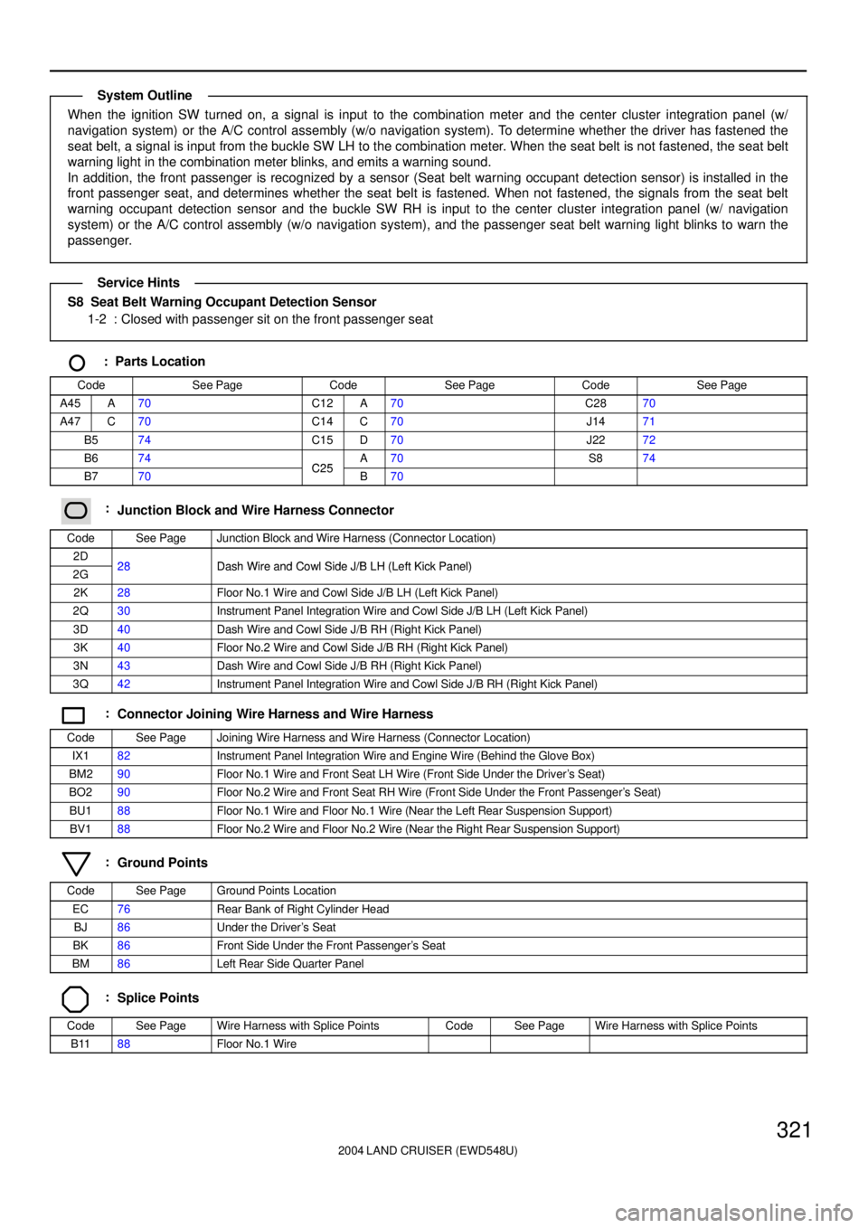
When the ignition SW turned on, a signal is input to the combination meter and the center cluster integration panel (w/
navigation system) or the A/C control assembly (w/o navigation system). To determine whether the driver has fastened the
seat belt, a signal is input from the buckle SW LH to the combination meter. When the seat belt is not fastened, the seat belt
warning light in the combination meter blinks, and emits a warning sound.
In addition, the front passenger is recognized by a sensor (Seat belt warning occupant detection sensor) is installed in the
front passenger seat, and determines whether the seat belt is fastened. When not fastened, the signals from the seat belt
warning occupant detection sensor and the buckle SW RH is input to the center cluster integration panel (w/ navigation
system) or the A/C control assembly (w/o navigation system), and the passenger seat belt warning light blinks to warn the
passenger.
S8 Seat Belt Warning Occupant Detection Sensor
1-2 : Closed with passenger sit on the front passenger seat
: Parts Location
CodeSee PageCodeSee PageCodeSee Page
A45A70C12A70C2870
A47C70C14C70J1471
B574C15D70J2272
B674C25A70S874
B770C25B70
:Junction Block and Wire Harness Connector
CodeSee PageJunction Block and Wire Harness (Connector Location)
2D28Dash Wire and Cowl Side J/B LH (Left Kick Panel)2G28Dash Wire and Cowl Side J/B LH (Left Kick Panel)
2K28Floor No.1 Wire and Cowl Side J/B LH (Left Kick Panel)
2Q30Instrument Panel Integration Wire and Cowl Side J/B LH (Left Kick Panel)
3D40Dash Wire and Cowl Side J/B RH (Right Kick Panel)
3K40Floor No.2 Wire and Cowl Side J/B RH (Right Kick Panel)
3N43Dash Wire and Cowl Side J/B RH (Right Kick Panel)
3Q42Instrument Panel Integration Wire and Cowl Side J/B RH (Right Kick Panel)
:Connector Joining Wire Harness and Wire Harness
CodeSee PageJoining Wire Harness and Wire Harness (Connector Location)
IX182Instrument Panel Integration Wire and Engine Wire (Behind the Glove Box)
BM290Floor No.1 Wire and Front Seat LH Wire (Front Side Under the Driver's Seat)
BO290Floor No.2 Wire and Front Seat RH Wire (Front Side Under the Front Passenger's Seat)
BU188Floor No.1 Wire and Floor No.1 Wire (Near the Left Rear Suspension Support)
BV188Floor No.2 Wire and Floor No.2 Wire (Near the Right Rear Suspension Support)
:Ground Points
CodeSee PageGround Points Location
EC76Rear Bank of Right Cylinder Head
BJ86Under the Driver's Seat
BK86Front Side Under the Front Passenger's Seat
BM86Left Rear Side Quarter Panel
:Splice Points
CodeSee PageWire Harness with Splice PointsCodeSee PageWire Harness with Splice Points
B1188Floor No.1 Wire
System Outline
Service Hints