1998 TOYOTA LAND CRUISER sensor
[x] Cancel search: sensorPage 2119 of 3115
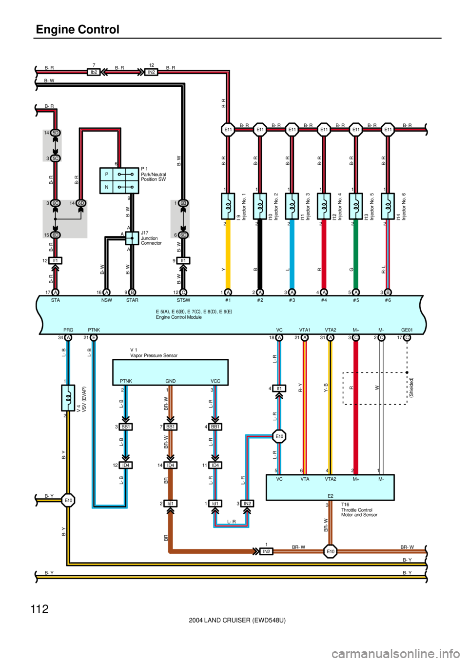
2004 LAND CRUISER (EWD548U)
11 2Engine Control
E 5(
A)
, E 6(
B)
, E 7(
C)
, E 8(
D)
, E 9(
E) 2 1
YB-R
#1A 1
I 92 1
BB-R
A 2
I102 1
LB-R
A 3
I112 1
RB-R
A 4
I122 1
GB-R
A 5
I132 1
R- L B- R
B 3
I14
IN212
Ib27
B 9A A P
N
14 6D
15 6D36C
A 17
B- W
B- W B- R
5D 14
5C 3
6
9
6B 1
6D 6
C 12
B- W B- WB- R
B- R
B- W
B- RP 1
A
AJ17B- R B- R B- R B- R B- R B- R
#3 #2 #4 #5 #6 STSW STAR NSW STA
E 21
3 BB1
ID4 12BB1 7
ID4 14
Id1 2BB1 4
ID4 11
Id1 1IN23If1 4A 18
L- R
A 21 A31
L- R
C 3C2
L- R
C 17
5
R- Y
Y- B
R
W
6421
T1 6
B- YV 1
213
L- B
BR- W
L- R L- B
BR- W
L- R L- B
BR
L- R
L- R
L- R
BR- W
BR
PTNK GND VCC
VC VTA VTA2 M+ M- 2 1A 34
B- Y
B- Y L- B
L- B B- Y
V 4
B- Y
B- Y PRG PTNKVC VTA1 VTA2 M+ M- GE01
(
Shielded)
3E2
BR- W
E10E10
E10E11 E11 E11 E11 E11 E11 B- R B- WB- R B- R B- R
IN21
BR- W 16
Engine Control Module
Injector No. 1
Injector No. 2
Injector No. 3
Injector No. 4
Injector No. 5
Injector No. 6
Park/Neutral
Position SW
Vapor Pressure Sensor
VSV (
EVAP)
Throttle Control
Motor and Sensor Junction
Connector
B- R
B- W
If1 9 If1 12
Page 2120 of 3115
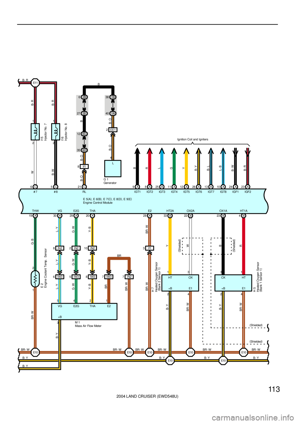
2004 LAND CRUISER (EWD548U)
11 3
2 1
WB-R
C 6
I152 1
B- W B- R
C 5
I16
B- R
E 5(
A)
, E 6(
B)
, E 7(
C)
, E 8(
D)
, E 9(
E) 6D 356C 122E 272B 6
1A 401B 38
C 21EE1 2
4
B- O B- OB B- O
L
G 1
A 9
IGT1B
A 8
IGT2
R
A 25
IGT3
L
A 11
IGT4
G
A 12
IGT5
Y
A 26
IGT6
B- Y
A 13
IGT7
B- L
A 10
IGT8
L- B
A 24
IGF1
B- W
A 23
IGF2
B- R
Ignition Coil and Igniters
1 2A 19
G- B BR- WIN2 8
IW3 6
L- Y
A 30
L- Y L- Y
5IN2 2
IW3 5
G- W
A 29
G- W G- W
4IN2 10
IW3 8
Y- B
A 20
Y- B Y- B
27IW3 IN27
1
BR
BR
BR- W
If1 3A 28
HTB 33 B22 B4 B 23
13 31
E 2
M 1 VG E2G THA E2
BR- W BR- W
OX
+B E1OX
H 7
H 5
HT
+B E1
(
Shielded)
(
Shielded)
BR- W
B- Y BR- W
B- Y BR- W
B- Y BR- W BR- W BR- W
B- Y
B- Y
WY
B
R B- Y
BR- W BR- WB- Y
24 24
(
Shielded) (
Shielded)
THW VG E2G THA E2 HT2A OX2A OX1A HT1A#7 #8 RL
3+B
B- Y
E11
E10E10
E10 E10E10 E10 E10
Engine Coolant Temp. Sensor
Engine Control ModuleGen erat or
Heated Oxygen Sensor
(
Bank 1 Sensor 1) Heated Oxygen Sensor
(
Bank 2 Sensor 1)Injector No. 7
Injector No. 8
Mass Air Flow MeterB
B- O
If1 8
Page 2121 of 3115
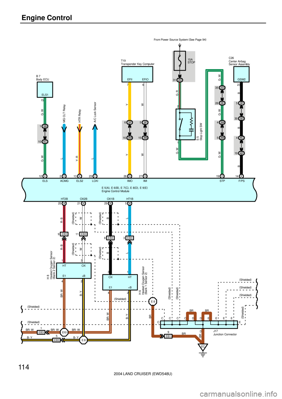
2004 LAND CRUISER (EWD548U)
11 4Engine Control
(
Shielded)
(
Shielded)
BR- W
B- YELS1
E 125C 105B 1
G- W G- W
15 B 7
D 2E13
MG CLT Relay
HTR Relay L
Y- R
ELS ACMG ELS2C 23
LCKI
A/C Lock Sensor
31 2D From Power Source System (
See Page 94)
15A
STOP
G- R
S 5
2D 35
2E 26
3M 4
3M 5
D 19
G- W
G- W G- W G- W
STP
EB31
EB35B 21 B 25
13
HT OX
E1 +B
R- B
W BR- W
B- Y
42 HT2B OX2B
9 EB3 EB311
R- B
W H 8
8 EB3 EB33 B 29 B5
31
EC CC
CCBR BR
CDDE
EB19
BR
BR BR- W BR- W42
BR- W
B- YEEE
E
J17(
Shielded)
(
Shielded)
(
Shielded)(
Shielded)B B
OX
(
Shielded)
HT
E1 +B
(
Shielded)
(
Shielded)
(
Shielded)(
Shielded)
(
Shielded)
E 5(
A)
, E 6(
B)
, E 7(
C)
, E 8(
D)
, E 9(
E)
OX1 B HT1B
(
Shielded)3F 5
3D 30
4C 4
4E 19
E 14
B B
F/ PS 23
B
GSW2
3P 6
3M 16
Y
26 D
IMO3P 5
3M 15
W
27 D
IMI
Y
W L L
BR
C26
B- Y
L
D 1 2Center Air bag
Sensor Assembly
Engine Control Module
Heated Oxygen Sensor
(
Bank 2 Sensor 2)
Stop Light SW
Junction Connector Body ECU
E10
E 8E 8
Heated Oxygen Sensor
(
Bank 1 Sensor 2) H 6
T1 9
Transponder Key Computer
7EFII
6 EFIO
Page 2122 of 3115
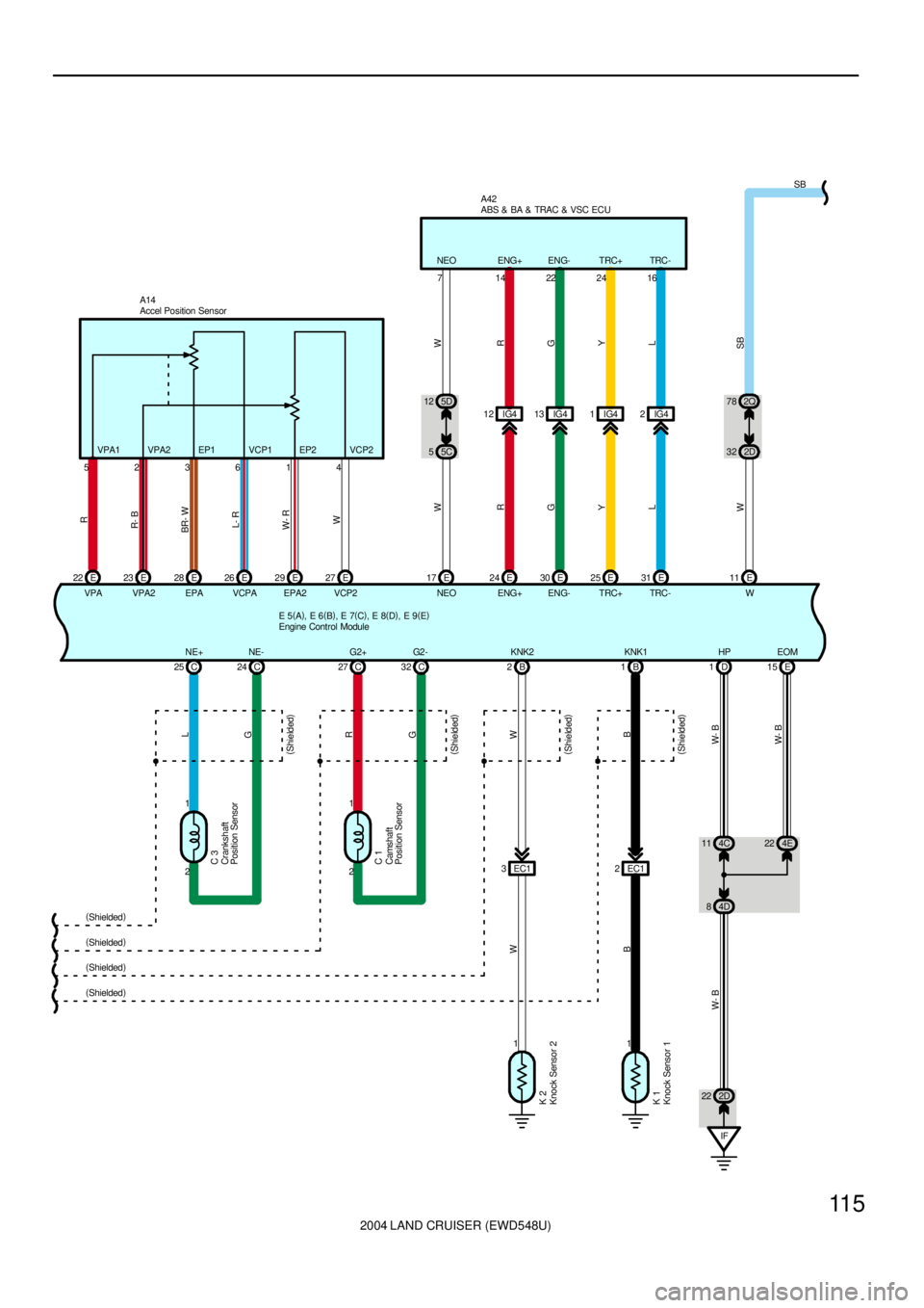
2004 LAND CRUISER (EWD548U)
11 5
2 1C 25 C24C 3L
G2 1C 27 C32C 1R
G
(
Shielded)
(
Shielded)
(
Shielded)
(
Shielded)
11B 2B1
EC1 3EC12
K 2
K 1W
B W
B
IF 4C 11 4E22
4D 8D 1
2D 22E 15
(
Shielded)
(
Shielded)
(
Shielded)
(
Shielded)
W- B
W- B W- B
E 5(
A)
, E 6(
B)
, E 7(
C)
, E 8(
D)
, E 9(
E)
NE+ NE- G2+ G2- KNK2 KNK1 HP EOM5D 12
5C 5IG4 12
R WW
ENG+ 24 E 17 E
R
714ENG+
IG4 13
G
ENG- 30 E
G
22ENG-
IG4 1
Y
TRC+ 25 E
Y
24TRC+
IG4 2
L
TRC- 31 E
L
16TRC- NEO
NEO2Q 78
2D 32
W
11 E
W
SB
SB
A42
E 22
VPAE 23
VPA2E 28
EPAE 26
VCPAE 29
EPA2E 27
VCP2
R
R- B
BR- W
L- R
W- R
W
523614VPA1 VPA2 EP1 VCP1 EP2 VCP2A14
Accel Position SensorABS & BA & TRAC & VSC ECU
Camshaft
Position Sensor Crankshaft
Position Sensor
Engine Control Module
Knock Sensor 1 Knock Sensor 2
Page 2124 of 3115
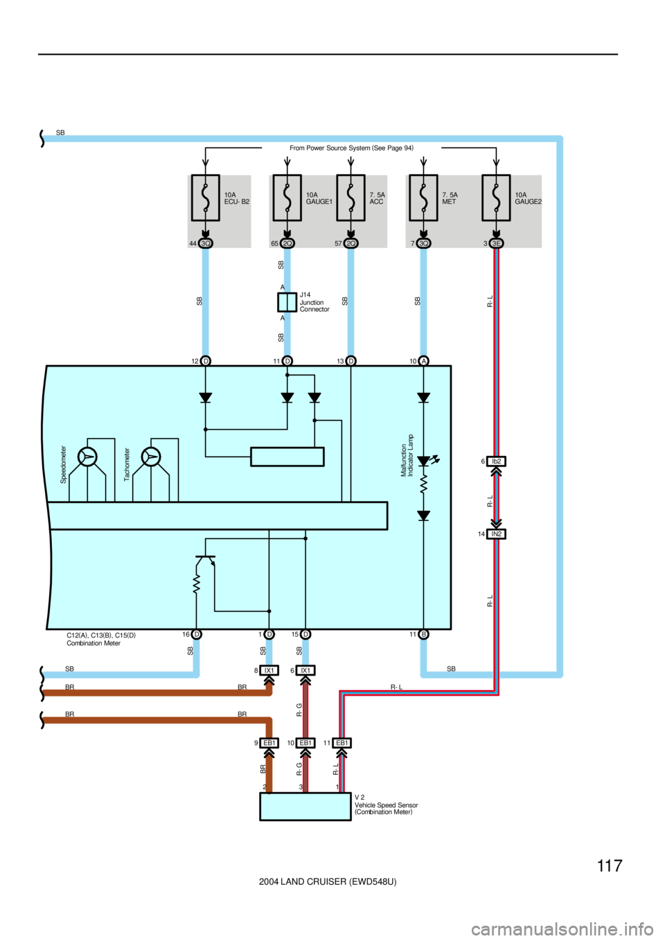
2004 LAND CRUISER (EWD548U)
11 7
Malfunction
Indicator Lamp
10A
ECU- B2From Power Source System (
See Page 94)
3Q 4410A
GAUGE1
2Q 65 57 2Q7. 5A
ACC
D 12 D11 D13 A10 A A
SB
SBSB SB
SB
D 16B 11
SBD 15 D 1
IX1 6 IX1 8
EB1 10 EB1 9
3 2
SB
V 2
SB
R- G BR
R- G
7. 5A
MET
3Q 7
SB
SB J14
SBTachometer Speedometer
Vehicle Speed Sensor
(
Combination Meter) Junction
Connector
C12(
A)
, C13(
B)
, C15(
D)
Combination Meter
EB1 11
1
R- L
10A
GAUGE2
3E 3
R- L
IN2 14
R- L R- L
Ib2 6
R- L BR
BRBR
BR
Page 2125 of 3115

2004 LAND CRUISER (EWD548U)
11 8Engine Control
The engine control system utilizes a microcomputer and maintains overall control of the engine, transmission etc. An outline
of the engine control is given here.
1. Input Signals
(1) Engine coolant temp. signal circuit
The engine coolant temp. sensor detects the engine coolant temp. and has a built-in thermistor with a resistance which
varies according to the engine coolant temp. The engine coolant temp. is input into TERMINAL THW of the engine
control module as a control signal.
(2) Intake air temp. signal circuit
The intake air temp. sensor is installed in the mass air flow meter and detects the intake air temp., which is input as a
control signal to TERMINAL THA of the engine control module.
(3) Oxygen sensor signal circuit
The oxygen density in the exhaust emission is detected and is input as a control signal from the heated oxygen sensors
to TERMINALS OX1A, OX1B, OX2A, OX2B of the engine control module.
(4) RPM signal circuit
The camshaft position is detected by the camshaft position sensor and is input into TERMINAL G2+ of the engine
control module as a control signal. Also, the engine RPM is detected by the crankshaft position sensor and the signal is
input into TERMINAL NE+ of the engine control module.
(5) Throttle position sensor signal circuit
The throttle position sensor detects the throttle valve opening angle as a control signal, which is input into TERMINALS
VTA1, VTA2 of the engine control module.
(6) Vehicle speed circuit
The vehicle speed sensor (Combination meter) detects the vehicle speed, and the signal is input into TERMINAL SPD
of the engine control module via the combination meter.
(7) Battery signal circuit
Voltage is constantly applied to TERMINAL BATT of the engine control module. When the ignition SW is turned on, the
voltage for engine control module start up power supply is applied through the EFI OR ECD relay, to TERMINALS +B,
+B2 of the engine control module. The current from the IGN fuse flows to TERMINAL IGSW of the engine control
module, and voltage is constantly applied to TERMINAL +BM.
(8) Intake air volume signal circuit
The intake air volume is detected by the mass air flow meter, and is input as a control signal to TERMINAL VG of the
engine control module.
(9) Stop light SW signal circuit
The stop light SW is used to detect whether the vehicle is braking or not, and the signal is input into TERMINAL STP of
the engine control module as a control signal.
(10) Starter signal circuit
To confirm whether the engine is cranking, the voltage applied to the starter motor when the engine is cranking is
detected, and is input into TERMINAL STA of the engine control module as a control signal.
(11) Engine knock signal circuit
Engine knocking is detected by the knock sensors, and is input into TERMINALS KNK1, KNK2 of the engine control
module as a control signal.
System Outline
Page 2126 of 3115

2004 LAND CRUISER (EWD548U)
11 9
2. Control System
*SFI system
The SFI system monitors the engine condition through the signals input from each sensors to the engine control module.
The control signal is sent to the engine control module TERMINALS #1, #2, #3, #4, #5, #6, #7, #8 to operate the injector
(Fuel injection). The SFI system controls the fuel injection by the engine control module in response to the driving
conditions.
*ESA system
The ESA system monitors the engine condition through the signals input from each sensors to the engine control module.
The best ignition timing is decided according to this data and the data memorized in the engine control module. The
control signal is output to TERMINALS IGT1, IGT2, IGT3, IGT4, IGT5, IGT6, IGT7, IGT8, and these signals control the
igniter to provide the best ignition timing.
*Heated oxygen sensor heater control system
The heated oxygen sensor heater control system turns the heater on when the intake air volume is low (Temp. of exhaust
emission is low), and warms up the heated oxygen sensors to improve their detection performance. The engine control
module evaluates the signals from each sensors, and outputs current to TERMINALS HT1A, HT1B, HT2A, HT2B to
control the heater.
*Fuel pump control system
The engine control module supplies current to TERMINAL FPR, and controls the operation speed of the fuel pump by the
F/PUMP relay.
*ACIS
The ACIS includes a valve in the bulkhead separating the surge tank into two parts. This valve is opened and closed in
accordance with the driving conditions to control the intake manifold length in two stages, for increased engine output in all
ranges from low to high speeds.
*ETCS-i
The ETCS-i controls the engine output at its optimal level in accordance with the opening of the accelerator pedal, under
all driving conditions.
3. Diagnosis System
When there is a malfunction in the engine control module signal system, the malfunctioning system is recorded in the
memory. The malfunctioning system can be found by reading the code displayed on the malfunction indicator lamp.
4. Fail-Safe System
When a malfunction has occurred in any system, there is a possibility of causing engine trouble due to continued control
based on that system. In that case, the fail-safe system either controls the system using the data (Standard values)
recorded in the engine control module memory, or else stops the engine.
E2 Engine Coolant Temp. Sensor
1-2 : Approx. 15.0 kW (-20°C, -4°F)
: Approx. 2.45 kW (20°C, 68°F)
: Approx. 0.32 kW (80°C, 176°F)
E5 (A), E7 (C), E8 (D), E9 (E) Engine Control Module
BATT-E1 : Always 9.0-14.0 volts
+BM-E1 : Always 9.0-14.0 volts
IGSW-E1 : 9.0-14.0 volts with ignition SW at ON or ST position
+B, +B2-E1 : 9.0-14.0 volts with ignition SW at ON or ST position
VC-E2 : 4.5-5.5 volts with ignition SW on
VTA2-E2 : 2.0-2.9 volts with ignition SW on and accelerator pedal released
: 4.6-5.1 volts with ignition SW on and accelerator pedal depressed
VTA1-E2 : 0.4-1.0 volts with ignition SW on and accelerator pedal released
: 3.2-4.8 volts with ignition SW on and accelerator pedal depressed
THA-E2 : 0.5-3.4 volts with idling, intake air temp. 20°C (68°F)
THW-E2 : 0.2-1.0 volts with idling, engine coolant temp. 80°C (176°F)
W-E1 : 9.0-14.0 volts with idling
: Below 3.0 volts with ignition SW on
Service Hints
Page 2171 of 3115
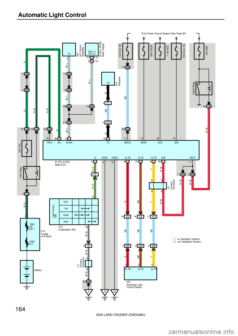
2004 LAND CRUISER (EWD548U)
164Automatic Light Control
B 7(
A)
, B 9(
C) 5B 4
5D 3
15A AM2
From Power Source System (
See Page 94)
1C 2
TAIL Relay
G 15A TAIL
120A
J/B
NO. 1
140A
ALTF15
Battery 11B 67
A 28 2B 24 1B 49
HEAD Relay
22 1B
52B 11 2E C 20
HeadTail OFF
Light Control
SW
Auto
II3 316
A A
II 3E 35
J 3
W- B W- B W- B
C 3
II5 1
IU3 17 IU3 18 IU316 C 6C21 C4
CLTS CLTB CLTE4 36B
A31B
YSB SB
SB YR
BR
Y
CLTS CLTB CLTE
E
E C 53E 26
3E 213D 13 4A 17
4A 8A 17(
*1)
B 3(
*2)
10A ECU- IG17. 5A ACC B- G
G- B
G- B
G
W- LG
W- L W- L
W- L
IDL TRLY 183TCDR(
*1)
TC(
*2)
ACAN
A47
M 5(
A)
, M 9(
B)
R- W R- W R- WR- W R- W
17HRLY HF2
J 9G- O G- O
A
12
C16
10A ECU- B2
SB
2Q 223Q 71
11 22 10
SIG ACC BECU TCC 18 4IF1
IU3 4
BSB
TC
5R 6 B
* 2 : w/o Navigation System * 1 : w/ Navigation System
Automatic Light
Contr ol Sensor Combination SW
Multi- Display
RheostatA/C Control
Assembly
Body ECU
Junction
Connector Junction
Connector
Fusible
Link Block16 GND1 GND2
4
IG IF
BRR
25A DOOR
12
BDR1
IM2 1IM23IM22