Page 2632 of 3115
 Acceptable 30
20
10
5
3
2
1
0.5
0.3
0.2
0.1
40 -20 0 20 60 80 100
(212) (176) (140) (104) (68) (32) (-4)
SF-50
- SFIENGI")
SF0PO-17
B02308
S01196S01699Z17274
Ohmmeter
Resistance kW
Temperature °C (°F) Acceptable 30
20
10
5
3
2
1
0.5
0.3
0.2
0.1
40 -20 0 20 60 80 100
(212) (176) (140) (104) (68) (32) (-4)
SF-50
- SFIENGINE COOLANT TEMPERATURE (ECT) SENSOR
1749 Author�: Date�:
2004 LAND CRUISER (RM1071U)
INSPECTION
1. DRAIN ENGINE COOLANT
2. REMOVE V-BANK COVER
3. REMOVE INTAKE AIR CONNECTOR
4. DISCONNECT THROTTLE BODY FROM INTAKE MAN-
IFOLDS (See page SF-36)
5. REMOVE ECT SENSOR
(a) Disconnect the ECT sensor connector.
(b) Remove the ECT sensor and the gasket.
6. INSPECT ECT SENSOR
Using an ohmmeter, measure the resistance between the ter-
minals.
Resistance: Refer to the graph
If the resistance is not as specified, replace the ECT sensor.
7. REINSTALL ECT SENSOR
(a) Install a new gasket and the ECT sensor.
Torque: 20.4 N´m (208 kgf´cm, 15 ft´lbf)
(b) Connect the ECT sensor connector.
8. REINSTALL THROTTLE BODY TO INTAKE MAN-
IFOLDS
Install a new gasket and the throttle body with the 2 bolts and
2 nuts.
Torque: 18 N´m (185 kgf´cm, 13 ft´lbf)
9. REINSTALL INTAKE AIR CONNECTOR
10. REFILL WITH ENGINE COOLANT (See page CO-2)
11. REINSTALL V-BANK COVER
Page 2644 of 3115
B16438
Fuel Main Tube
Tube Joint Clip
Fuel Pump & Sender Gauge
Connector
Fuel Tank Vent Tube Set Plate
Fuel Pump and Sender
Gauge Assembly
� Gasket
Tube Joint Clip
N´m (kgf´cm, ft´lbf) : Specified torque
� Non-reusable part
3.5 (35, 31 in.´lbf)
Vapor Pressure Sensor & Connector
Fuel Return Tube
x 8
Tube Joint Clip
Tube Joint Clip
- SFIFUEL PUMP
SF-1 1
1710 Author�: Date�:
2004 LAND CRUISER (RM1071U)
Page 2652 of 3115
SF0Y9-09
B16456
N´m (kgf´cm, ft´lbf)
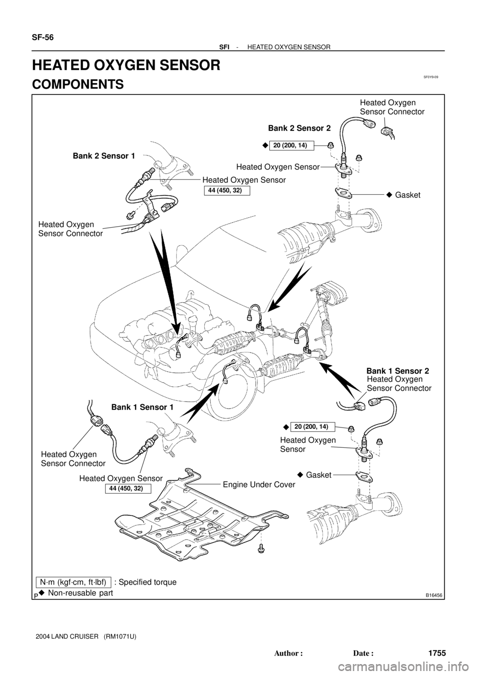
� Non-reusable part: Specified torqueHeated Oxygen
Sensor Connector
Heated Oxygen Sensor
� Gasket
Engine Under Cover Bank 2 Sensor 1
Bank 2 Sensor 2
44 (450, 32)
20 (200, 14)
Heated Oxygen Sensor
Bank 1 Sensor 2
Bank 1 Sensor 1
Heated Oxygen
Sensor Connector
Heated Oxygen Sensor
Heated Oxygen
Sensor Connector
Heated Oxygen
Sensor
20 (200, 14)
� Gasket
44 (450, 32)
Heated Oxygen
Sensor Connector
� �
SF-56
- SFIHEATED OXYGEN SENSOR
1755 Author�: Date�:
2004 LAND CRUISER (RM1071U)
HEATED OXYGEN SENSOR
COMPONENTS
Page 2653 of 3115
SF0YA-12
B04936B04937B04998
Sensor 1
Sensor 2Ohmmeter
OhmmeterHT
+B
HT+B
- SFIHEATED OXYGEN SENSOR
SF-57
1756 Author�: Date�:
2004 LAND CRUISER (RM1071U)
INSPECTION
1. INSPECT HEATER RESISTANCE OF HEATED OXY-
GEN SENSORS
(a) Disconnect the oxygen sensor connector.
(b) Using an ohmmeter, measure the resistance between ter-
minal +B and HT.
Resistance: 11 - 16 W at 20°C (68°F)
If the resistance is not as specified, replace the sensor.
Torque:
44 N´m (450 kgf´cm, 32 ft´lbf) for sensor 1
20 N´m (200 kgf´cm, 14 ft´lbf) for sensor 2
(c) Reconnect the oxygen sensor connector.
2. INSPECT OPERATION OF HEATED OXYGEN SEN-
SORS (See pages DI-106 and DI-138)
Page 2664 of 3115
SF0PR-14
B16447
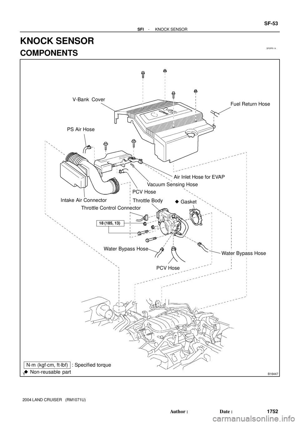
N´m (kgf´cm, ft´lbf)V-Bank Cover
PS Air Hose
Intake Air ConnectorAir Inlet Hose for EVAP
PCV Hose
� Gasket Throttle Body
18 (185, 13)
� Non-reusable part: Specified torque
Vacuum Sensing Hose
Fuel Return Hose
Throttle Control Connector
Water Bypass HoseWater Bypass Hose
PCV Hose
- SFIKNOCK SENSOR
SF-53
1752 Author�: Date�:
2004 LAND CRUISER (RM1071U)
KNOCK SENSOR
COMPONENTS
Page 2665 of 3115
B16455
PS Air Hose Engine Wire Clamp
V-Bank Cover Bracket
Engine Wire ProtectorAir Inlet Hose for EVAP
Injector Connector
� Gasket VSV for EVAP
EVAP Hose
x 6
18 (185, 13)
Engine Wire Clamp
N´m (kgf´cm, ft´lbf): Specified torque
� Non-reusable part
18 (185, 13)
Knock Sensor 1 ConnectorKnock Sensor 2 Knock Sensor 2 Connector
VSV Connector
for EVAP
Fuel Main Hose
Knock Sensor 1Fuel Return Hose
Upper and Lower Intake
Manifolds Assembly
SF-54
- SFIKNOCK SENSOR
1753 Author�: Date�:
2004 LAND CRUISER (RM1071U)
Page 2666 of 3115
SF0PS-10
B04429
Ohmmeter
No Continuity
B04430
SST
- SFIKNOCK SENSOR
SF-55
1754 Author�: Date�:
2004 LAND CRUISER (RM1071U)
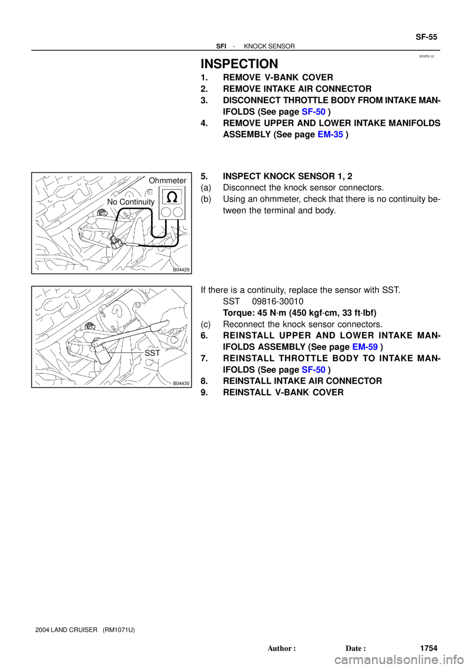
INSPECTION
1. REMOVE V-BANK COVER
2. REMOVE INTAKE AIR CONNECTOR
3. DISCONNECT THROTTLE BODY FROM INTAKE MAN-
IFOLDS (See page SF-50)
4. REMOVE UPPER AND LOWER INTAKE MANIFOLDS
ASSEMBLY (See page EM-35)
5. INSPECT KNOCK SENSOR 1, 2
(a) Disconnect the knock sensor connectors.
(b) Using an ohmmeter, check that there is no continuity be-
tween the terminal and body.
If there is a continuity, replace the sensor with SST.
SST 09816-30010
Torque: 45 N´m (450 kgf´cm, 33 ft´lbf)
(c) Reconnect the knock sensor connectors.
6. REINSTALL UPPER AND LOWER INTAKE MAN-
IFOLDS ASSEMBLY (See page EM-59)
7. REINSTALL THROTTLE BODY TO INTAKE MAN-
IFOLDS (See page SF-50)
8. REINSTALL INTAKE AIR CONNECTOR
9. REINSTALL V-BANK COVER
Page 2669 of 3115

SFI SYSTEM
PRECAUTION
1. BEFORE WORKING ON FUEL SYSTEM, DISCON-
NECT NEGATIVE (-) TERMINAL CABLE FROM BAT-
TERY
HINT:")
SF0XU-1 1
- SFISFI SYSTEM
SF-1
1700 Author�: Date�:
2004 LAND CRUISER (RM1071U)
SFI SYSTEM
PRECAUTION
1. BEFORE WORKING ON FUEL SYSTEM, DISCON-
NECT NEGATIVE (-) TERMINAL CABLE FROM BAT-
TERY
HINT:
Any diagnostic trouble code retained by the computer will be
erased when the negative (-) terminal cable is removed from
the battery.
Therefore, if necessary, read the diagnosis before removing the
negative (-) terminal cable from the battery.
2. DO NOT SMOKE OR WORK NEAR AN OPEN FLAME
WHEN WORKING ON THE FUEL SYSTEM
3. KEEP GASOLINE AWAY FROM RUBBER OR
LEATH-
ER PARTS
4. MAINTENANCE PRECAUTIONS
(a) Take following precautions to prevent the engine misfire.
(1) Check proper connection to battery terminals, etc.
(2) After repair work, check that the ignition coil termi-
nals and all other ignition system lines are recon-
nected securely.
(3) When cleaning the engine compartment, be espe-
cially careful to protect the electrical system from
water.
(b) Take following precautions to handle the oxygen sensor.
(1) Do not drop the oxygen sensor or hit against an ob-
ject.
(2) Do not allow the sensor to contact with water.
5. IF VEHICLE IS EQUIPPED WITH MOBILE RA-
DIO
SYSTEM (HAM, CB, ETC.)
If the vehicle is equipped with a mobile communication system,
refer to the precaution in the IN section.
6. AIR INDUCTION SYSTEM
(a) Separation of the engine oil dipstick, oil filler cap, PCV
hose, etc. may cause the engine to be out of tune.
(b) Disconnection, looseness or cracks in the parts of the air
induction system between the throttle body and cylinder
head will cause air suction, which makes the engine out
of tune.
7. ELECTRONIC CONTROL SYSTEM
(a) Disconnect the power by either turning the ignition switch
OFF or disconnecting the negative (-) terminal cable from
the battery before removing SFI wiring connectors, termi-
nals, etc.
HINT:
Always check the diagnostic trouble code before disconnecting
the negative (-) terminal cable from the battery.
(b) When installing the battery, be especially careful not to in-
correctly connect the positive (+) and negative (-) cables.