Page 236 of 3115
BE02Q-23
I25526 I06215
ECM Transponder Key CoilEngine Room R/B
� EFI Fuse
� EFI and ECD Relay
DLC3
Transponder Key Amplifier
Passenger Side Junction Block
� IGN Fuse
- BODY ELECTRICALENGINE IMMOBILISER SYSTEM
BE-195
2568 Author�: Date�:
2004 LAND CRUISER (RM1071U)
LOCATION
Page 339 of 3115

BE-6
- BODY ELECTRICALTROUBLESHOOTING
2379 Author�: Date�:
2004 LAND CRUISER (RM1071U) Rear washer motor does not operate.
1. Rear Washer Motor
2. Rear Washer Switch
3. Wire HarnessBE-52
BE-52
-
Washer fluid does not operate.1. Washer Hose and Nozzle-
*1: Inspect wiper arm and blade set positions.
COMBINATION METER (Meter Gauges and Illumination):
SymptomSuspect AreaSee page
Tachometer, fuel gauge and engine coolant temperature gauge do
not operate.1. GAUGE2 Fuse
2. Combination Meter
3. Wire Harness-
BE-58
-
Speedometer does not operate.
1. Speed Sensor
2. Combination Meter
3. Wire HarnessBE-63
BE-58
-
Tachometer does not operate.
1. Igniter
2. Combination Meter
3. Wire HarnessIG-1
BE-58
-
Fuel gauge does not operate or is in abnormal operation.
1. Fuel Receiver Gauge
2. Fuel Sender Gauge
3. Combination Meter
4. Wire HarnessBE-63
BE-63
BE-58
-
Oil pressure gauge does not operate.
1. Oil Pressure Receiver Gauge
2. Oil Pressure Sender Gauge
3. Combination Meter
4. Wire HarnessBE-63
BE-63
BE-58
-
Voltmeter does not operate.
1. Voltmeter
2. Combination Meter
3. Wire HarnessBE-63
BE-58
-
Engine coolant temperature gauge does not operate or is in ab-
normal operation
1. Engine Coolant Temperature Receiver Gauge
2. Engine Coolant Temperature Sender Gauge
3. Combination Meter
4. Wire HarnessBE-63
BE-63
BE-58
-
All illumination lights do not light up.1. Light Control Rheostat
2. Wire HarnessBE-63
-
Brightness does not change even when rheostat is turned.1. Bulb
2. Wire Harness-
-
Only one illumination light does not light up.1. Bulb
2. Wire Harness-
-
COMBINATION METER (Warning Light):
SymptomSuspect AreaSee page
Warning lights do not light up. (Except discharge, open door and
SRS)1. GAUGE1 Fuse
2. Combination Meter
3. Wire Harness-
BE-58
-
Fuel level warning light does not light up.
1. LED
2. Combination Meter
3. Fuel Sender Gauge
4. Wire Harness-
BE-58
BE-63
-
ABS warning light does not light up.
1. LED
2. ABS ECU
3. Wire Harness-
DI-502
-
Page 341 of 3115

BE-8
- BODY ELECTRICALTROUBLESHOOTING
2381 Author�: Date�:
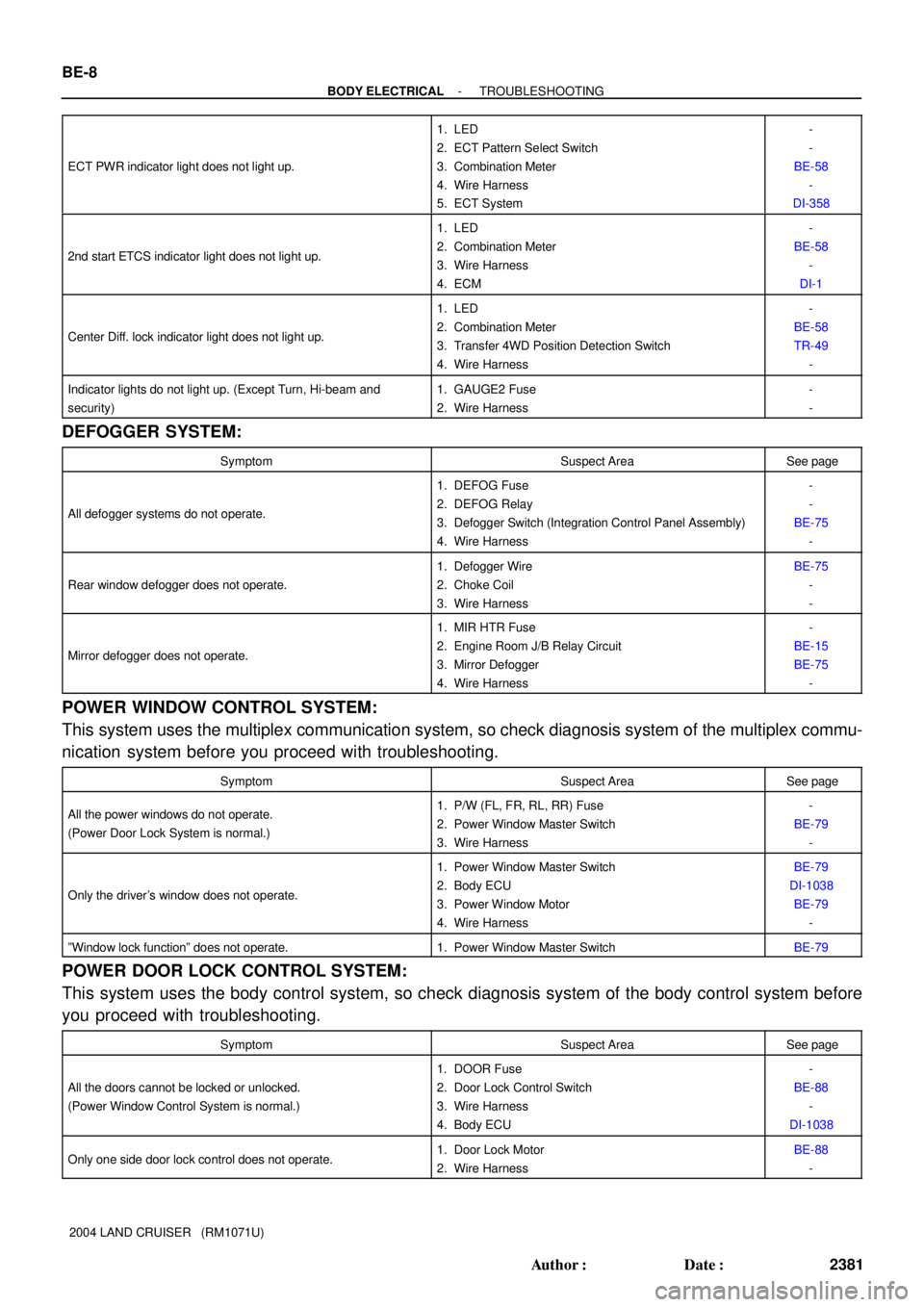
2004 LAND CRUISER (RM1071U) ECT PWR indicator light does not light up.
1. LED
2. ECT Pattern Select Switch
3. Combination Meter
4. Wire Harness
5. ECT System-
-
BE-58
-
DI-358
2nd start ETCS indicator light does not light up.
1. LED
2. Combination Meter
3. Wire Harness
4. ECM-
BE-58
-
DI-1
Center Diff. lock indicator light does not light up.
1. LED
2. Combination Meter
3. Transfer 4WD Position Detection Switch
4. Wire Harness-
BE-58
TR-49
-
Indicator lights do not light up. (Except Turn, Hi-beam and
security)1. GAUGE2 Fuse
2. Wire Harness-
-
DEFOGGER SYSTEM:
SymptomSuspect AreaSee page
All defogger systems do not operate.
1. DEFOG Fuse
2. DEFOG Relay
3. Defogger Switch (Integration Control Panel Assembly)
4. Wire Harness-
-
BE-75
-
Rear window defogger does not operate.
1. Defogger Wire
2. Choke Coil
3. Wire HarnessBE-75
-
-
Mirror defogger does not operate.
1. MIR HTR Fuse
2. Engine Room J/B Relay Circuit
3. Mirror Defogger
4. Wire Harness-
BE-15
BE-75
-
POWER WINDOW CONTROL SYSTEM:
This system uses the multiplex communication system, so check diagnosis system of the multiplex commu-
nication system before you proceed with troubleshooting.
SymptomSuspect AreaSee page
All the power windows do not operate.
(Power Door Lock System is normal.)1. P/W (FL, FR, RL, RR) Fuse
2. Power Window Master Switch
3. Wire Harness-
BE-79
-
Only the driver's window does not operate.
1. Power Window Master Switch
2. Body ECU
3. Power Window Motor
4. Wire HarnessBE-79
DI-1038
BE-79
-
ºWindow lock functionº does not operate.1. Power Window Master SwitchBE-79
POWER DOOR LOCK CONTROL SYSTEM:
This system uses the body control system, so check diagnosis system of the body control system before
you proceed with troubleshooting.
SymptomSuspect AreaSee page
All the doors cannot be locked or unlocked.
(Power Window Control System is normal.)
1. DOOR Fuse
2. Door Lock Control Switch
3. Wire Harness
4. Body ECU-
BE-88
-
DI-1038
Only one side door lock control does not operate.1. Door Lock Motor
2. Wire HarnessBE-88
-
Page 602 of 3115
CH06H-09
B16651N´m (kgf´cm, ft´lbf): Specified torque
Radiator Reservoir Tank
Fan Shroud
A/T Oil Cooler Hose Bracket
Fan Pulley
Generator Drive Belt
x 8Engine Under Cover No. 1
BracketWire
A/C Discharge Tube
Clamp
Clamp
Radiator Lower
Hose
Radiator Upper
HoseGrommet
Fan with
Fluid Coupling Radiator Asembly
Clamp
Generator Generator
Wire
Generator ConnectorPS Vane Pump Pulley
9.8 (100, 87 in.´lbf)
39 (400, 29)
15.5 (158, 11)
39 (400, 29)
5.0 (50, 43 in.´lbf)
20 (200, 15)
20 (200, 15)
20 (200, 15)
- CHARGINGGENERATOR
CH-5
1840 Author�: Date�:
2004 LAND CRUISER (RM1071U)
GENERATOR
COMPONENTS
Page 744 of 3115

CO0IO-06
- COOLINGCOOLANT
CO-1
1762 Author�: Date�:
2004 LAND CRUISER (RM1071U)
COOLANT
INSPECTION
HINT:
Check the coolant level when the engine is cold.
1. CHECK ENGINE COOLANT LEVEL AT RADIATOR RESERVOIR
The engine coolant level should be between the ºLOWº and ºFULLº lines at normal temperature
(20°C(68°F)).
If low, check for leaks and add ºToyota Super Long Life Coolantº or similar high quality ethylene glycol based
non-silicate, non-amine, non-nitrite, and non-borate coolant with long-life hybrid organic acid technology
up to the ºFULLº line.
2. CHECK ENGINE COOLANT QUALITY
(a) Remove the radiator cap.
CAUTION:
To avoid the danger of being burned, do not remove the radiator cap while the engine and radiator
are still hot, as fluid and steam can be blown out under pressure.
(b) There should not be any excessive deposits of rust or scale around the radiator cap or radiator filler
hole, and the coolant should be free from oil.
If excessively dirty, clean the coolant passages and replace the coolant.
(c) Reinstall the radiator cap.
Page 746 of 3115
CO0J0-02
B08313
Radiator Reservoir Tank
Fan Shroud
Radiator AssemblyA/T Oil Cooler Hose
Engine Under Cover No.1
Radiator AssemblyRadiator Upper
HoseRadiator Lower
Hose
Fan Pulley
Generator Drive Belt
x 8 Fan with
Fluid Coupling
RadiatorSide Support
Insulator Support Collar
Side Support12.7 (130, 9)
N´m (kgf´cm, ft´lbf) : Specified torque
5.0 (50, 43in.´lbf )
12.7 (130, 9)
20 (200, 15)
Grommet
A/C Discharge Tube
Wire BracketClamp
Clamp
Bracket Clamp
20 (200, 15)
Bracket
20 (200, 15)
CO-16
- COOLINGRADIATOR
1777 Author�: Date�:
2004 LAND CRUISER (RM1071U)
COMPONENTS
Page 747 of 3115

CO0J2-03
B08321
B04475
B08320
- COOLINGRADIATOR
CO-19
1780 Author�: Date�:
2004 LAND CRUISER (RM1071U)
INSTALLATION
1. INSTALL SIDE SUPPORTS TO RADIATOR
(a) Install the 2 side support with 8 nuts.
Torque: 12.7 N´m (130 kgf´cm, 9 ft´lbf)
(b) Install the 2 brackets with the 4 nuts.
Torque: 20 N´m (200 kgf´cm, 13 ft´lbf)
2. INSTALL RADIATOR ASSEMBLY
(a) Place the radiator assembly to the body.
(b) Install the 2 nuts.
Torque: 20 N´m (200 kgf´cm, 15 ft´lbf)
(c) Install the radiator assembly with the 2 bolts to the body.
Torque: 18 N´m (185 kgf´cm, 13 ft´lbf)
3. INSTALL FAN PULLEY, FAN SHROUD, FAN WITH
FLUID COUPLING AND GENERATOR DRIVE BELT
(a) Place the fan with fluid coupling, fan pulley and fan shroud
in position.
(b) Temporarily install the fan pulley mounting nuts.
(c) Install the fan shroud with the 3 bolts.
Torque: 5.0 N´m (50 kgf´cm, 43 in.´lbf)
(d) Connect the A/T oil cooler hoses to the clamp on the fan
shroud.
(e) Install the generator drive belt. (See page CH-16)
(f) Tighten the 4 fan pulley mounting nuts.
(g) Install the 2 brackets on wire to the radiator wire with 2
bolts.
(h) Install the 2 clamps on the A/C discharge tube to the
brackets on the wire with the 2 nuts.
4. INSTALL RADIATOR RESERVOIR
(a) Install the grommet to the reservoir.
(b) Attach the lower side of the reservoir to the fun shuroud.
(c) install the reservoir with the 2 bolts.
(d) Connect the reservoir hose to the radiator.
(e) Install the clamp on the wire to the radiator.
5. CONNECT A/T OIL COOLER HOSES TO RADIATOR
6. CONNECT RADIATOR UPPER HOSE TO RADIATOR
7. CONNECT RADIATOR LOWER HOSE TO RADIATOR
8. FILL WITH ENGINE COOLANT
9. START ENGINE AND CHECK FOR ENGINE COOLANT
LEAKS
10. RECHECK ENGINE COOLANT LEVEL
Page 751 of 3115

CO0J1-02
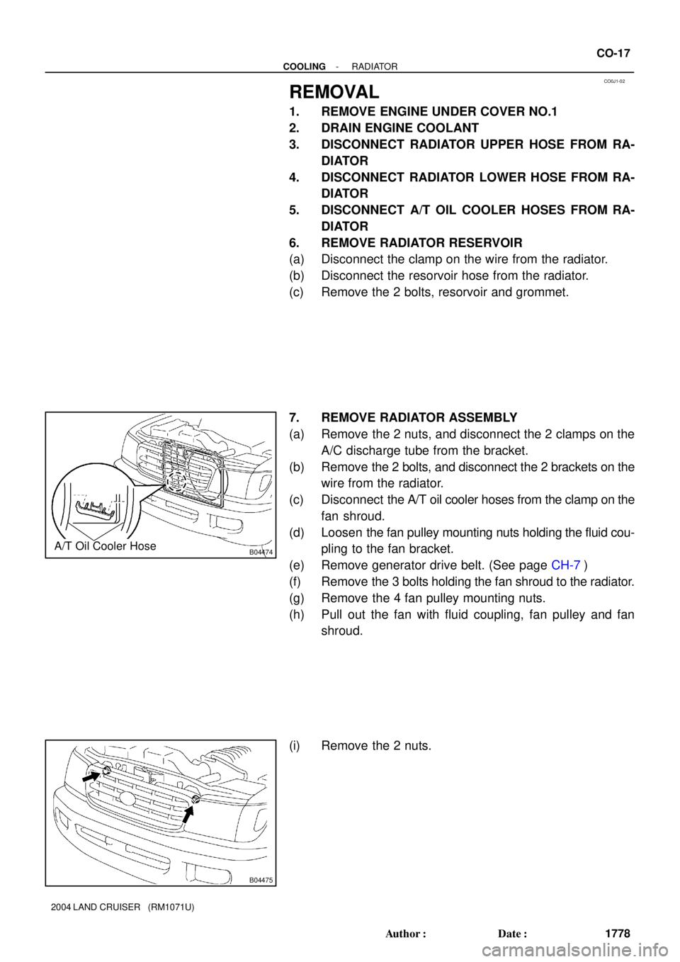
B04474A/T Oil Cooler Hose
B04475
- COOLINGRADIATOR
CO-17
1778 Author�: Date�:
2004 LAND CRUISER (RM1071U)
REMOVAL
1. REMOVE ENGINE UNDER COVER NO.1
2. DRAIN ENGINE COOLANT
3. DISCONNECT RADIATOR UPPER HOSE FROM RA-
DIATOR
4. DISCONNECT RADIATOR LOWER HOSE FROM RA-
DIATOR
5. DISCONNECT A/T OIL COOLER HOSES FROM RA-
DIATOR
6. REMOVE RADIATOR RESERVOIR
(a) Disconnect the clamp on the wire from the radiator.
(b) Disconnect the resorvoir hose from the radiator.
(c) Remove the 2 bolts, resorvoir and grommet.
7. REMOVE RADIATOR ASSEMBLY
(a) Remove the 2 nuts, and disconnect the 2 clamps on the
A/C discharge tube from the bracket.
(b) Remove the 2 bolts, and disconnect the 2 brackets on the
wire from the radiator.
(c) Disconnect the A/T oil cooler hoses from the clamp on the
fan shroud.
(d) Loosen the fan pulley mounting nuts holding the fluid cou-
pling to the fan bracket.
(e) Remove generator drive belt. (See page CH-7)
(f) Remove the 3 bolts holding the fan shroud to the radiator.
(g) Remove the 4 fan pulley mounting nuts.
(h) Pull out the fan with fluid coupling, fan pulley and fan
shroud.
(i) Remove the 2 nuts.