Page 3553 of 6000
10A–2
CRUISE CONTROL SYSTEM
2. RESUME/ACCEL Switch Function
1.Resume Function: When the RESUME/ACCEL
switch is turned on/off after the system is temporarily
deactivated by pressing the brake or clutch pedal
while the vehicle is running, the vehicle resumes the
speed stored before the system was released, and
the vehicle automatically runs at the stored speed .
2.Accelerate Function: When the RESUME/ACCEL
switch is kept on after the system is released
completely, the vehicle accelerates its speed during
t h a t t i m e . T h e v e h i c l e s p e e d a t w h i c h t h e v e h i c l e w a s
running when the switch was turned off is stored in the
memory, and the vehicle automatically returns to this
speed.
3.Tap-up Function: When the RESUME/ACCEL
switch is turned on and off instantaneously while the
vehicle is running, the vehicle decelerates a mile for
each on/off operation. The vehicle speed at which the
vehicle was running when the switch was turned off
last is stored in the memory, and the vehicle
automatically returns to this stored speed.
3. CANCEL Function
1.Temporary Cancellation:
When the brake pedal is pressed.
When the clutch pedal is pressed. (M/T)
When the select lever is shifted to any position other
than “D”, “3”, “2” or “L”. (A/T)
When the cancel switch is operated.
When the vehicle speed exceeds about 20 km/h
over the vehicle speed stored in the memory.
Turning the RESUME/ACCEL switch will return the
vehicle to the speed stored in the cruise control
memory.
2.Complete Cancellation:
When the starter switch or the main switch is turned
off.
When the fail-safe function is activated.
When the vehicle speed is about 38.5 km/h.
Diagnosis
Refer to the Cruise Control System Diagnosis in Wiring
System section.
Brake Switch
Removal
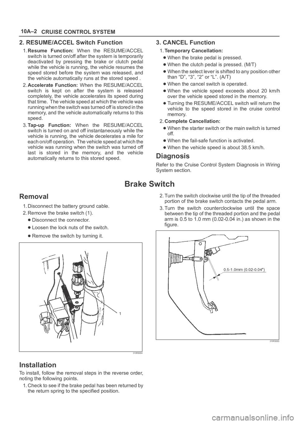
1. Disconnect the battery ground cable.
2. Remove the brake switch (1).
Disconnect the connector.
Loosen the lock nuts of the switch.
Remove the switch by turning it.
310RS004
Installation
To install, follow the removal steps in the reverse order,
noting the following points.
1. Check to see if the brake pedal has been returned by
the return spring to the specified position.2. Turn the switch clockwise until the tip of the threaded
portion of the brake switch contacts the pedal arm.
3. Turn the switch counterclockwise until the space
between the tip of the threaded portion and the pedal
arm is 0.5 to 1.0 mm (0.02-0.04 in.) as shown in the
figure.
310RS003
Page 3554 of 6000
10A–3
CRUISE CONTROL SYSTEM
Adjustment
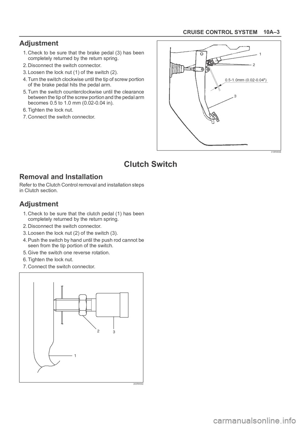
1. Check to be sure that the brake pedal (3) has been
completely returned by the return spring.
2. Disconnect the switch connector.
3. Loosen the lock nut (1) of the switch (2).
4. Turn the switch clockwise until the tip of screw portion
of the brake pedal hits the pedal arm.
5. Turn the switch counterclockwise until the clearance
between the tip of the screw portion and the pedal arm
becomes 0.5 to 1.0 mm (0.02-0.04 in).
6. Tighten the lock nut.
7. Connect the switch connector.
310RW006
Clutch Switch
Removal and Installation
Refer to the Clutch Control removal and installation steps
in Clutch section.
Adjustment
1. Check to be sure that the clutch pedal (1) has been
completely returned by the return spring.
2. Disconnect the switch connector.
3. Loosen the lock nut (2) of the switch (3).
4. Push the switch by hand until the push rod cannot be
seen from the tip portion of the switch.
5. Give the switch one reverse rotation.
6. Tighten the lock nut.
7. Connect the switch connector.
203RW002
Page 3691 of 6000
B-5
BLOWER
MOTOR2
B-5
1
I-51
3I-51
I-51I-51
MAX HI
RELAY POWER
TRANSISTORI-50
I-50
4
H-202
H-26
10
1
3
H-20
121 2L/B
0.5P/G
12
I-32
16 I-32
P-2
0.85W/G5W
5W 0.5R/W
0.3B0.5R/W 0.3R/W
TAIL RELAY(4) ILLUMINATION
CONTROLLER0.5G/R 0.85G/R
1.25B
1.25B1.25B
0.5B
9 I-32 5W 3W
BATT
FL-1
80A
MAIN4B-36
33L/R
C-19 25A
BLOWERC-20 10A
AIR CON
3L 2L/B
0.3BR
0.5BR0.3BR 2/B 0.3GR
0.3GR/L0.5L/B
2/B
B-36
20
H-27 2
B-36H-14
1
B-36HEATER & A/C RELAY
STARTER RELAY(1)
H-141
H-1310
I-328
H-269
10 C-16
10A CLOCK ROOM
BODY-RHBODY-LH
B-18
B-19
B-1
AUTO A/C CONTROL UNITAUTO A/C CONTROL UNIT
I-3217
14 35 2112 337
I-32
22
29 6I-331 H-20
14
H-16
M
192B
I-33
2I-50
D08RY00118
Page 3695 of 6000
0.5R/G
ILLUMINATION
CONTROLLER
12
I-32
157
I-32
16 I-3229
P-2
0.85W/R5W
3L 2L/B 2L/BBATT.
5W 0.5R/W
0.3B0.5R/W 0.3R/W
TAIL REAY(4) 0.5G/R 0.85R/W
1.25B
1.25B
0.5B
9 I-3236 5W 3W FL-1
80A
MAIN4
B-36
33L/RC-20 10A
AIR CON
C-19 25A
BLOWER
BLOWER
MOTOR
B-36 2
B-36H-14
1
B-36HEATER A/C RELAY
STARTER SW (ACC)
H-141
I-328
H-265
10 C-16 10A
CLOCK ROOM
C-11 10A
AUDIO
F-12 10A
TAIL-RH
BODY-LHB-19
BODY-RHB-22BH-481.25B 15
H-2614
I-50 2
AUTO A/C CONTORL UNIT AUTO A/C CONTORL UNIT
I-32
6
H-16
0.5BR 2B 2B0.3GR/W0.5L/B
0.3BR 0.3BR
19
I-33
33
22 21 3512
H-48
0.3GR/L
MAX HI
RELAY POWER
TRANSISTOR
I-51
3
H-4811
I-51
4I-50
3
I-512I-501
H-4815
I-511
B-51
B-5
2
H-484
M
17
I-33
14
D08RY00121
Page 3699 of 6000
X-2124
13X-21
X-21THERMO SW RELAY
0.5BR 0.5BR
0.5G/Y
QWS THERMO SW 0.5G/BX-21
B-19
B-18
BODY-RH
BODY-RH
I-32 I-33I-32 I-32 I-33 I-33
84
I-329I-32107111213
12
B-36 B-36
B-36 B-3634
9
H-26
5W 3W
5W
3L/R
C-16
CLOCK, ROOM
BODY ENG. FRAME10A
0.5Y/B 0.5Y/B 0.5Y/B
0.5R/G
0.5G/R 0.5G/RILLUMINATION
CONTROLLER
TAIL RELAY (4) 0.5R/W 0.3R/W0.5R/W 0.5R/W
0.5BR 0.5BR
0.5BR
HEATER
& A/C RELAY CHARGE
RELAY(1)
P-1
P-5
P-2
P-7P-10P-6
5B30B8B
8B/R
FL-1
80A MAIN
+
�ー
AUTO A/C CONTROL UNIT
I-32
H-271.25B
0.5B
20
1.25B
I-3314
I-49
4612
M
I-49 I-49 I-49
I-493
5
I-49
16
0.5L/O
0.5L/W
0.3L/R
0.3L/Y
0.3B/L
1.25B0.3B
0.5BR
C-25C-25
2 1
H-26160.5G/W 0.5LGPRESSURE SW
INTAKE
ACTUATOR
H-141
H-1310
0.85W/G 0.85W/G
5W
0.5B
0.5BR
H-167
3
H-40.5Y/B 0.5Y/B
12
H-17
1
H-24
0.5BR
3W/LFL-3
40A C/HEAT
2H-410.5G/Y
ECM(J1-23)
H-2413
5
H-41
E-23THERMO UNIT
12
I-32
3L
2L/B 2L/B
C-19 25A
BLOWER
BLOWER
MOTOR C-20 10A
A/C
I-50 2
2B 2B
0.3GR/W0.5L/B
0.3BR 0.3BR 2L/B 2B
19
I-33
33 22 34 19 18 17 12
0.3GR/LMAX HI RELAY
POWER
TRANSISTOR
I-51
3
H-26
10
I-51
4I-50
3
I-512I-501I-511
B-52
B-5
1
H-20
2
17
I-33
14 35 36 7 21
29
H-201
M
B-1
D08RY00114
Page 3701 of 6000
X-2124
13X-21
X-21 THERMO SW RELAY
0.5BR 0.5BR
0.5G/Y
QWS THE R MO S W 0.5G/BX-21
B-2BODY-RH
B-19 BODY-LH
I-32 I-33I-32 I-32 I-33 I-33
847111213
12
B-36 B-36
B-36 B-3634
7
H-26
5W 3W
5W
3L/R
C-16
CLOCK, ROOM
10AC-19
25A
BLOWERC-20
10A A/C
0.5Y/B 0.5Y/B 0.5Y/B0.5R/W 0.3R/W0.5R/W 0.5R/W
0.5BR
0.5BR0.5L/B
0.3GR/W
2B
0.3GR/L
0.5BR
HEATER AND
A/C RELAY STARTER
SW (ACC)
P-1
P-5
P-2
P-7P-10P-6
5B
2L/B30B8B
8B/R
FL-1
80A MAIN
+
�ー
I-32
H-481.25B
0.5B
151.25B
I-33
7 21 14 12 2233 34 19 18 1714
I-49
4612
M
I-49 I-49 I-49
I-493
5
I-49
16
0.5L/O
0.5L/W
0.3L/R
0.3L/Y
0.3B/L
1.25B0.3B
0.5BR
C-25
I-3317I-3319
H-9
3L 2L/B
0.3BR 0.3BR
0.5BR
0.5BR
C-25
2 1 19
0.5G/W 0.5LGPRESSURE SW
INTAKE
ACTUATOR
MAX
HI
RELAY ELECTRONIC
THERMOSTAT
THERMO UNIT
H-141
I-502 0.5O/G
5W
0.3B
BODY ENG FRAME
H-167
3
H-4
E-23
1
H-9
ENGINE
0.5BR
3W/LFL-3
40A C/HEATER
2H-420.5G/Y
ECM(J1-23)
12
H-17
B-51
H-2614
I-501
B-5
2
I-50
3
15
H-48
4
H-48
MBLOWER
MOTOR
I-51
2
I-511
43I-51
I-51
AUTO A/C CONTROL UNIT
I-3212
11
H-48
D08RY00116
Page 3778 of 6000
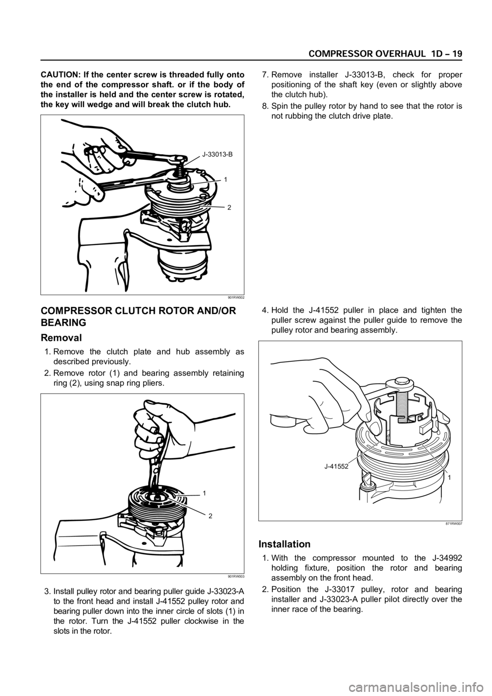
CAUTION: If the center screw is threaded fully onto
the end of the compressor shaft. or if the body of
the installer is held and the center screw is rotated,
the key will wedge and will break the clutch hub.7. Remove installer J-33013-B, check for proper
positioning of the shaft key (even or slightly above
the clutch hub).
8. Spin the pulley rotor by hand to see that the rotor is
not rubbing the clutch drive plate.
COMPRESSOR CLUTCH ROTOR AND/OR
BEARING
Removal
1. Remove the clutch plate and hub assembly as
described previously.
2. Remove rotor (1) and bearing assembly retaining
ring (2), using snap ring pliers.
3. Install pulley rotor and bearing puller guide J-33023-A
to the front head and install J-41552 pulley rotor and
bearing puller down into the inner circle of slots (1) in
the rotor. Turn the J-41552 puller clockwise in the
slots in the rotor.4. Hold the J-41552 puller in place and tighten the
puller screw against the puller guide to remove the
pulley rotor and bearing assembly.
Installation
1. With the compressor mounted to the J-34992
holding fixture, position the rotor and bearing
assembly on the front head.
2. Position the J-33017 pulley, rotor and bearing
installer and J-33023-A puller pilot directly over the
inner race of the bearing.
1
2 J-33013-B
901RW002
1
2
901RW003
J-41552
1
871RW007
Page 3781 of 6000
COMPRESSOR SHAFT SEAL
Service Precaution
When replacing the shaft seal assembly, pressure relief
valve or control switches, it will be necessary to recover
the refrigerant. Other than clutch repair procedures, the
same holds true for any disassembly of the compressor.
A clean workbench covered with a sheet of clean
paper, and a place (clean trays, etc) for all parts being
removed and replaced is important, as is the use of
proper clean service tools.
CAUTION: Any attempt to use makeshift or
inadequate service tools or equipment may result
in damage and/or improper compressor operation.
All parts required for servicing the internal compressor
are protected by a preservative process and packaged
in a manner which will eliminate the necessity of
cleaning, washing or flushing of the parts. The parts
can be used in the internal assembly just as they are
removed from the service package. Seals and
protective packaging should be left intact until just
prior to installation.
If the compressor rear head, front head or cylinder and
shaft assembly is to be serviced or replaced, the oil in
the compressor must be drained, measured, recorded
and replaced.
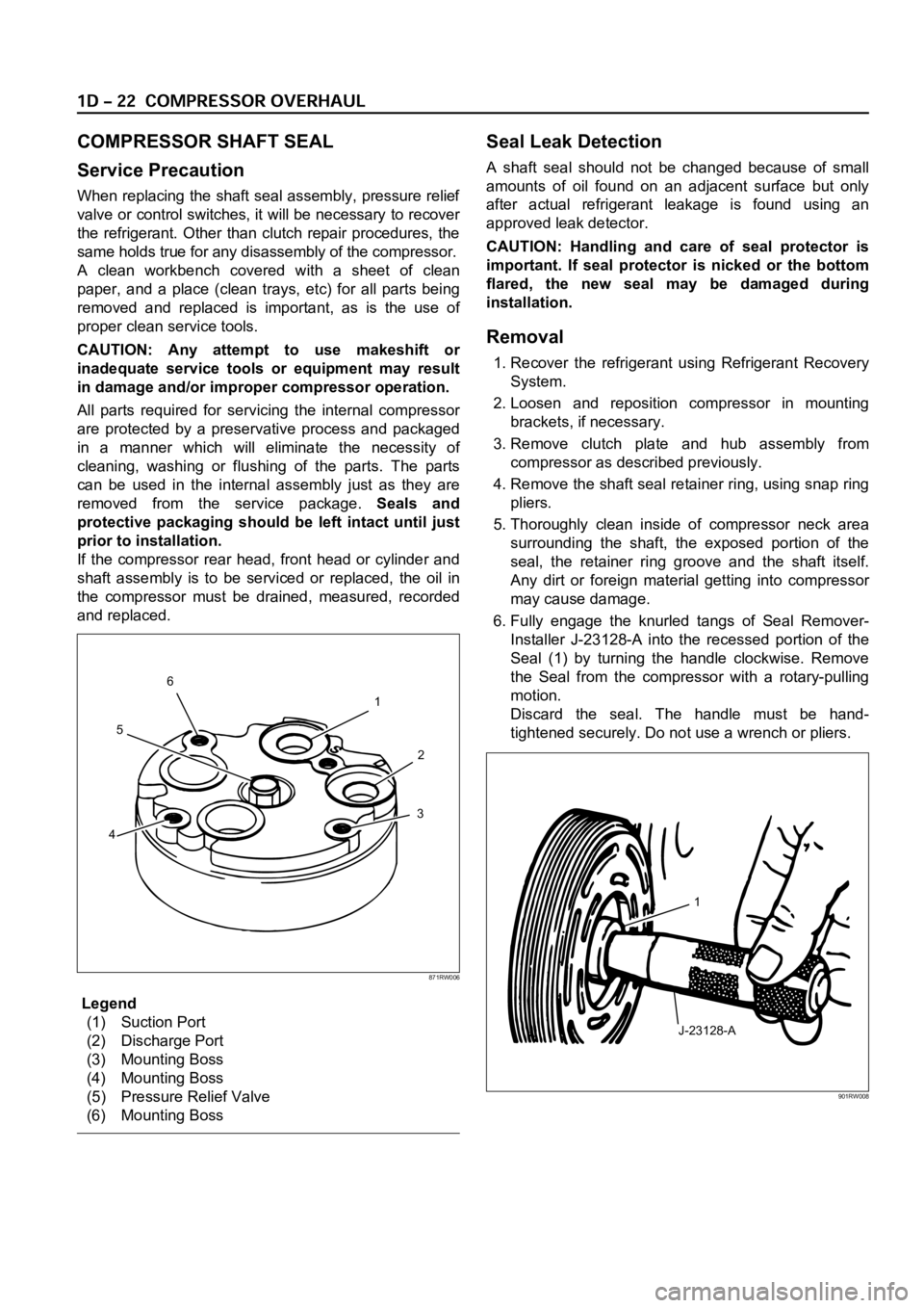
Legend
(1) Suction Port
(2) Discharge Port
(3) Mounting Boss
(4) Mounting Boss
(5) Pressure Relief Valve
(6) Mounting Boss
Seal Leak Detection
A shaft seal should not be changed because of small
amounts of oil found on an adjacent surface but only
after actual refrigerant leakage is found using an
approved leak detector.
CAUTION: Handling and care of seal protector is
important. If seal protector is nicked or the bottom
flared, the new seal may be damaged during
installation.
Removal
1. Recover the refrigerant using Refrigerant Recovery
System.
2. Loosen and reposition compressor in mounting
brackets, if necessary.
3. Remove clutch plate and hub assembly from
compressor as described previously.
4. Remove the shaft seal retainer ring, using snap ring
pliers.
5. Thoroughly clean inside of compressor neck area
surrounding the shaft, the exposed portion of the
seal, the retainer ring groove and the shaft itself.
Any dirt or foreign material getting into compressor
may cause damage.
6. Fully engage the knurled tangs of Seal Remover-
Installer J-23128-A into the recessed portion of the
Seal (1) by turning the handle clockwise. Remove
the Seal from the compressor with a rotary-pulling
motion.
Discard the seal. The handle must be hand-
tightened securely. Do not use a wrench or pliers.
1
2
3
456
871RW006
J-23128-A1
901RW008