1998 OPEL FRONTERA clock
[x] Cancel search: clockPage 3782 of 6000
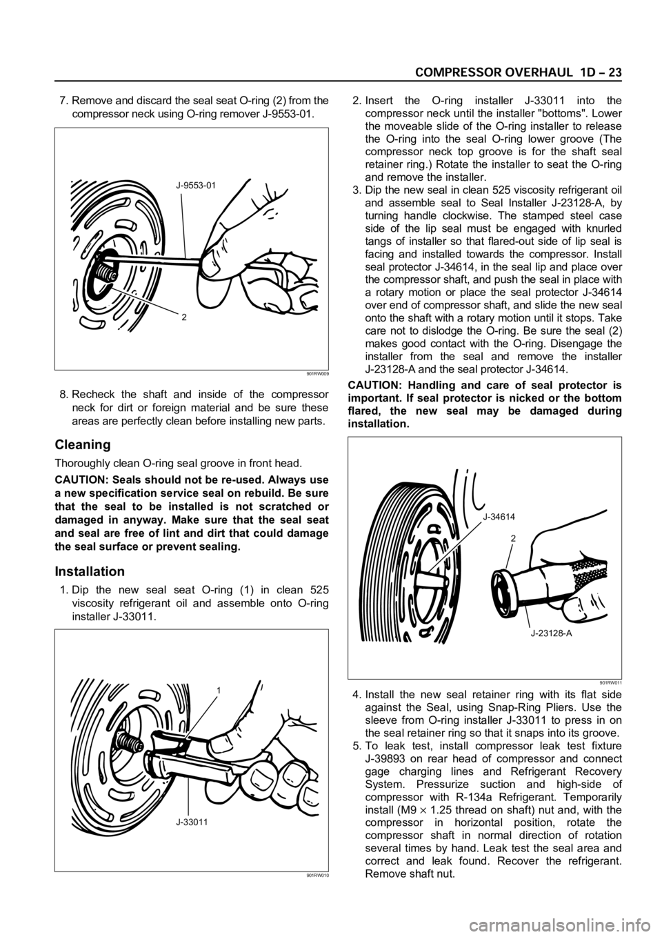
7. Remove and discard the seal seat O-ring (2) from the
compressor neck using O-ring remover J-9553-01.
8. Recheck the shaft and inside of the compressor
neck for dirt or foreign material and be sure these
areas are perfectly clean before installing new parts.
Cleaning
Thoroughly clean O-ring seal groove in front head.
CAUTION: Seals should not be re-used. Always use
a new specification service seal on rebuild. Be sure
that the seal to be installed is not scratched or
damaged in anyway. Make sure that the seal seat
and seal are free of lint and dirt that could damage
the seal surface or prevent sealing.
Installation
1. Dip the new seal seat O-ring (1) in clean 525
viscosity refrigerant oil and assemble onto O-ring
installer J-33011.2. Insert the O-ring installer J-33011 into the
compressor neck until the installer "bottoms". Lower
the moveable slide of the O-ring installer to release
the O-ring into the seal O-ring lower groove (The
compressor neck top groove is for the shaft seal
retainer ring.) Rotate the installer to seat the O-ring
and remove the installer.
3. Dip the new seal in clean 525 viscosity refrigerant oil
and assemble seal to Seal Installer J-23128-A, by
turning handle clockwise. The stamped steel case
side of the lip seal must be engaged with knurled
tangs of installer so that flared-out side of lip seal is
facing and installed towards the compressor. Install
seal protector J-34614, in the seal lip and place over
the compressor shaft, and push the seal in place with
a rotary motion or place the seal protector J-34614
over end of compressor shaft, and slide the new seal
onto the shaft with a rotary motion until it stops. Take
care not to dislodge the O-ring. Be sure the seal (2)
makes good contact with the O-ring. Disengage the
installer from the seal and remove the installer
J-23128-A and the seal protector J-34614.
CAUTION: Handling and care of seal protector is
important. If seal protector is nicked or the bottom
flared, the new seal may be damaged during
installation.
4. Install the new seal retainer ring with its flat side
against the Seal, using Snap-Ring Pliers. Use the
sleeve from O-ring installer J-33011 to press in on
the seal retainer ring so that it snaps into its groove.
5. To leak test, install compressor leak test fixture
J-39893 on rear head of compressor and connect
gage charging lines and Refrigerant Recovery
System. Pressurize suction and high-side of
compressor with R-134a Refrigerant. Temporarily
install (M9
1.25 thread on shaft) nut and, with the
compressor in horizontal position, rotate the
compressor shaft in normal direction of rotation
several times by hand. Leak test the seal area and
correct and leak found. Recover the refrigerant.
Remove shaft nut.
2 J-9553-01
901RW009
1
J-33011
901RW010
J-34614
2
J-23128-A
901RW011
Page 3953 of 6000
4A1–13 DIFFERENTIAL (FRONT)
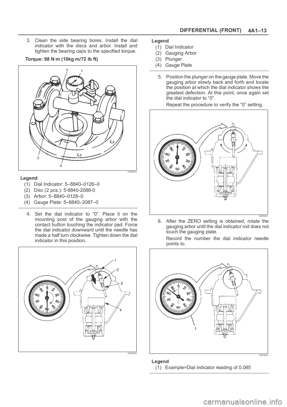
3. Clean the side bearing bores. Install the dial
indicator with the discs and arbor. Install and
tighten the bearing caps to the specified torque.
To r q u e : 9 8 N ꞏm ( 1 0 k g ꞏm / 7 2 l b f t )
415RS010
Legend
(1) Dial Indicator: 5–8840–0126–0
(2) Disc (2 pcs.): 5-8840-2088-0
(3) Arbor: 5–8840–0128–0
(4) Gauge Plate: 5–8840–2087–0
4. Set the dial indicator to “0”. Place it on the
mounting post of the gauging arbor with the
contact button touching the indicator pad. Force
the dial indicator downward until the needle has
made a half turn clockwise. Tighten down the dial
indicator in this position.
425RS020
Legend
(1) Dial Indicator
(2) Gauging Arbor
(3) Plunger
(4) Gauge Plate
5. Position the plunger on the gauge plate. Move the
gauging arbor slowly back and forth and locate
the position at which the dial indicator shows the
greatest defection. At this point, once again set
the dial indicator to “0”.
Repeat the procedure to verify the “0” setting.
425RS021
6. After the ZERO setting is obtained, rotate the
gauging arbor until the dial indicator rod does not
touch the gauging plate.
Record the number the dial indicator needle
points to.
425RS022
Legend
(1) Example=Dial indicator reading of 0.085
Page 3986 of 6000
DIFFERENTIAL (REAR 220mm)
4A2A–17
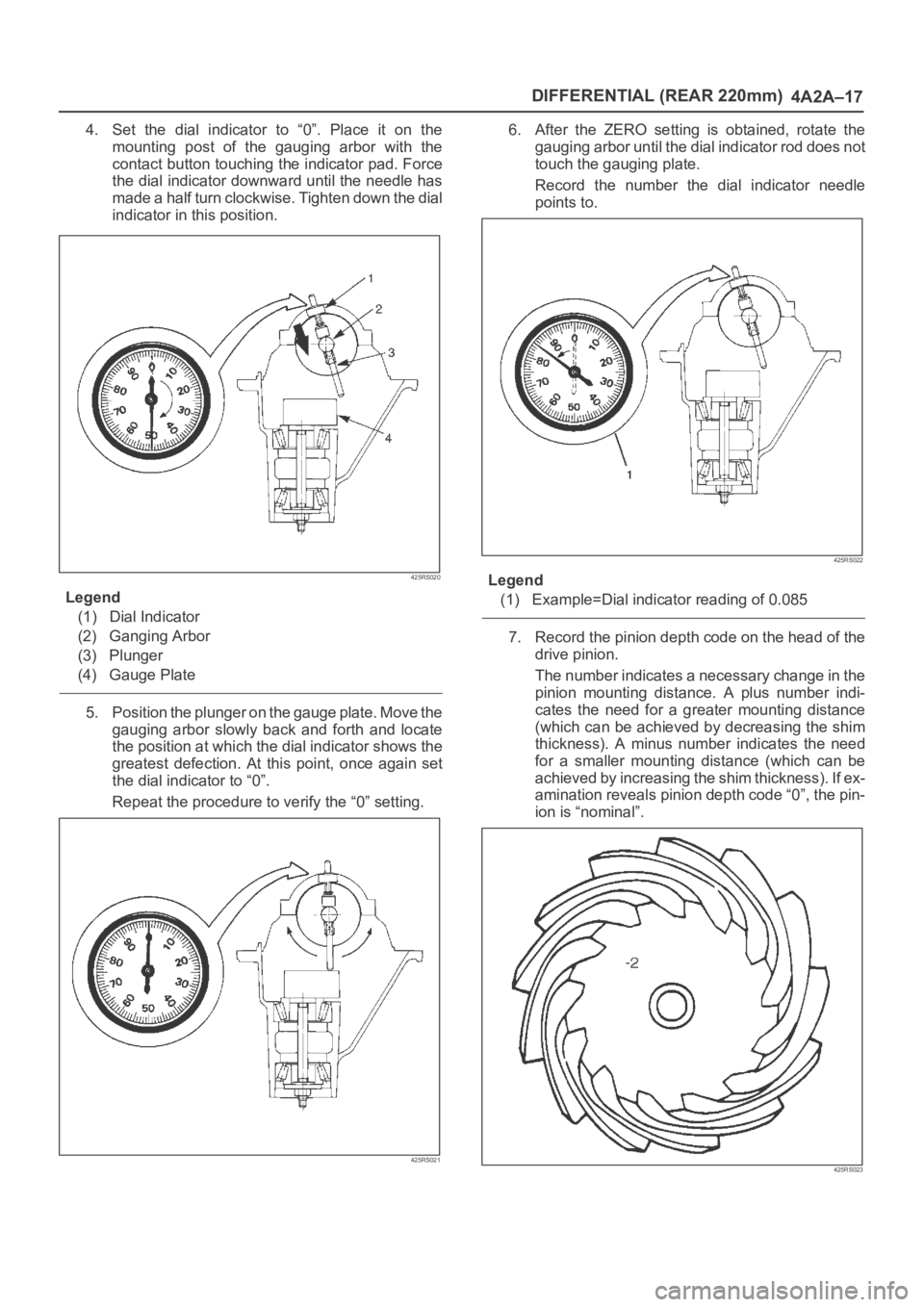
4. Set the dial indicator to “0”. Place it on the
mounting post of the gauging arbor with the
contact button touching the indicator pad. Force
the dial indicator downward until the needle has
made a half turn clockwise. Tighten down the dial
indicator in this position.
425RS020
Legend
(1) Dial Indicator
(2) Ganging Arbor
(3) Plunger
(4) Gauge Plate
5. Position the plunger on the gauge plate. Move the
gauging arbor slowly back and forth and locate
the position at which the dial indicator shows the
greatest defection. At this point, once again set
the dial indicator to “0”.
Repeat the procedure to verify the “0” setting.
425RS021
6. After the ZERO setting is obtained, rotate the
gauging arbor until the dial indicator rod does not
touch the gauging plate.
Record the number the dial indicator needle
points to.
425RS022
Legend
(1) Example=Dial indicator reading of 0.085
7. Record the pinion depth code on the head of the
drive pinion.
The number indicates a necessary change in the
pinion mounting distance. A plus number indi-
cates the need for a greater mounting distance
(which can be achieved by decreasing the shim
thickness). A minus number indicates the need
for a smaller mounting distance (which can be
achieved by increasing the shim thickness). If ex-
amination reveals pinion depth code “0”, the pin-
ion is “nominal”.
425RS023
Page 4025 of 6000
4A2B–18DIFFERENTIAL (REAR 244mm)
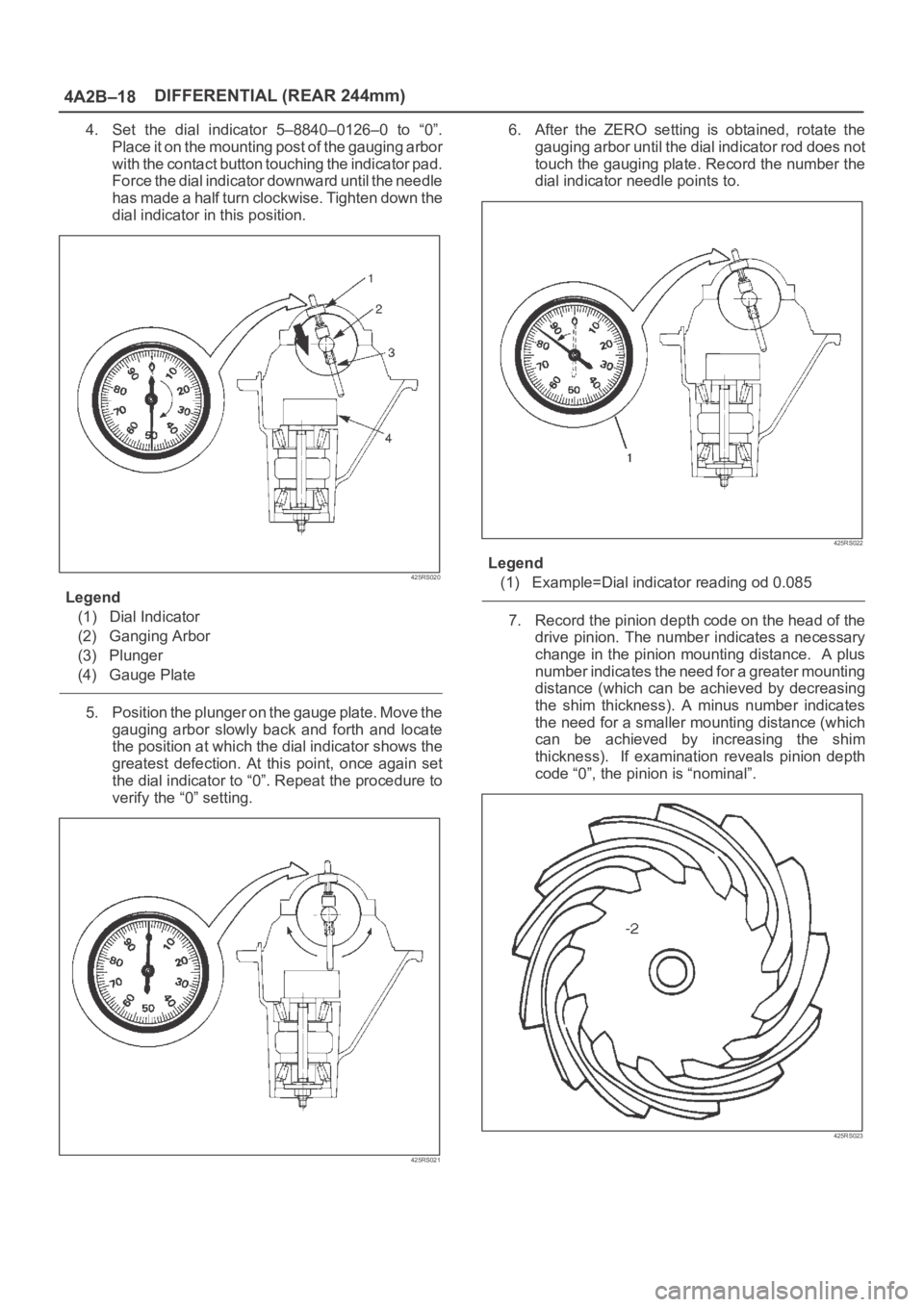
4. Set the dial indicator 5–8840–0126–0 to “0”.
Place it on the mounting post of the gauging arbor
with the contact button touching the indicator pad.
Force the dial indicator downward until the needle
has made a half turn clockwise. Tighten down the
dial indicator in this position.
425RS020
Legend
(1) Dial Indicator
(2) Ganging Arbor
(3) Plunger
(4) Gauge Plate
5. Position the plunger on the gauge plate. Move the
gauging arbor slowly back and forth and locate
the position at which the dial indicator shows the
greatest defection. At this point, once again set
the dial indicator to “0”. Repeat the procedure to
verify the “0” setting.
425RS021
6. After the ZERO setting is obtained, rotate the
gauging arbor until the dial indicator rod does not
touch the gauging plate. Record the number the
dial indicator needle points to.
425RS022
Legend
(1) Example=Dial indicator reading od 0.085
7. Record the pinion depth code on the head of the
drive pinion. The number indicates a necessary
change in the pinion mounting distance. A plus
number indicates the need for a greater mounting
distance (which can be achieved by decreasing
the shim thickness). A minus number indicates
the need for a smaller mounting distance (which
can be achieved by increasing the shim
thickness). If examination reveals pinion depth
code “0”, the pinion is “nominal”.
425RS023
Page 4221 of 6000
4C–15 DRIVE SHAFT SYSTEM
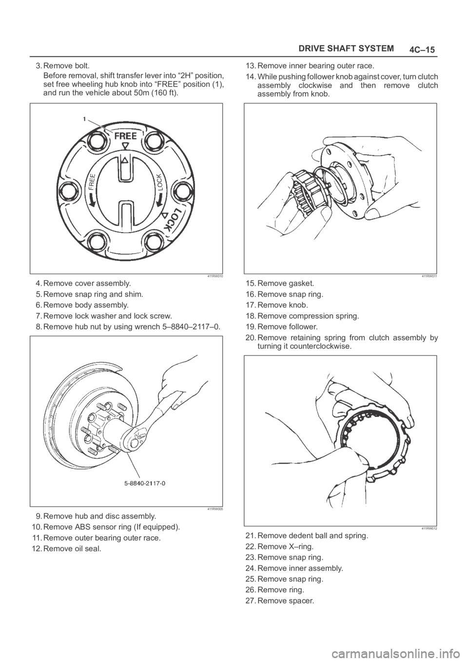
3. Remove bolt.
Before removal, shift transfer lever into “2H” position,
set free wheeling hub knob into “FREE” position (1),
and run the vehicle about 50m (160 ft).
411RW010
4. Remove cover assembly.
5. Remove snap ring and shim.
6. Remove body assembly.
7. Remove lock washer and lock screw.
8. Remove hub nut by using wrench 5–8840–2117–0.
411RW005
9. Remove hub and disc assembly.
10. Remove ABS sensor ring (If equipped).
11. Remove outer bearing outer race.
12. Remove oil seal.13. Remove inner bearing outer race.
14. While pushing follower knob against cover, turn clutch
assembly clockwise and then remove clutch
assembly from knob.
411RW011
15. Remove gasket.
16. Remove snap ring.
17. Remove knob.
18. Remove compression spring.
19. Remove follower.
20. Remove retaining spring from clutch assembly by
turning it counterclockwise.
411RW012
21. Remove dedent ball and spring.
22. Remove X–ring.
23. Remove snap ring.
24. Remove inner assembly.
25. Remove snap ring.
26. Remove ring.
27. Remove spacer.
Page 4223 of 6000
4C–17 DRIVE SHAFT SYSTEM
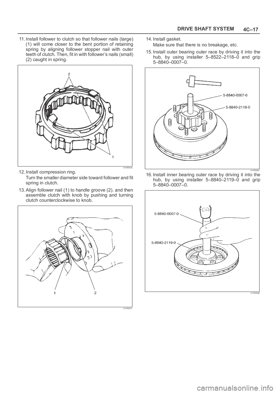
11. Install follower to clutch so that follower nails (large)
(1) will come closer to the bent portion of retaining
spring by aligning follower stopper nail with outer
teeth of clutch. Then, fit in with follower’s nails (small)
(2) caught in spring.
411RW016
12. Install compression ring.
Turn the smaller diameter side toward follower and fit
spring in clutch.
13. Align follower nail (1) to handle groove (2). and then
assemble clutch with knob by pushing and turning
clutch counterclockwise to knob.
411RW017
14. Install gasket.
Make sure that there is no breakage, etc.
15. Install outer bearing outer race by driving it into the
hub, by using installer 5–8522–2118–0 and grip
5–8840–0007–0.
411RW007
16. Install inner bearing outer race by driving it into the
hub, by using installer 5–8840–2119–0 and grip
5–8840–0007–0.
411RW006
Page 4281 of 6000
4D1–20
TRANSFER CASE (STANDARD TYPE)
Removal
1. Remove the speedometer sensor.
2. Remove the plate.
3. Remove the speedometer driven gear bushing and
driven gear.
NOTE: Apply a reference mark to the driven gear bushing
before removal.
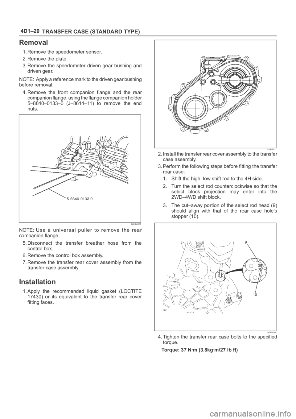
4. Remove the front companion flange and the rear
companion flange, using the flange companion holder
5–8840–0133–0 (J–8614–11) to remove the end
nuts.
262RW067
NOTE: Use a universal puller to remove the rear
companion flange.
5. Disconnect the transfer breather hose from the
control box.
6. Remove the control box assembly.
7. Remove the transfer rear cover assembly from the
transfer case assembly.
Installation
1. Apply the recommended liquid gasket (LOCTITE
17430) or its equivalent to the transfer rear cover
fitting faces.
220RS017
2. Install the transfer rear cover assembly to the transfer
case assembly.
3. Perform the following steps before fitting the transfer
rear case:
1. Shift the high–low shift rod to the 4H side.
2. Turn the select rod counterclockwise so that the
select block projection may enter into the
2WD–4WD shift block.
3. The cut–away portion of the select rod head (9)
should align with that of the rear case hole’s
stopper (10).
230RW004
4. Tighten the transfer rear case bolts to the specified
torque.
Torque: 37 Nꞏm (3.8kgꞏm/27 lb ft)
Page 4527 of 6000
6A–31
ENGINE MECHANICAL
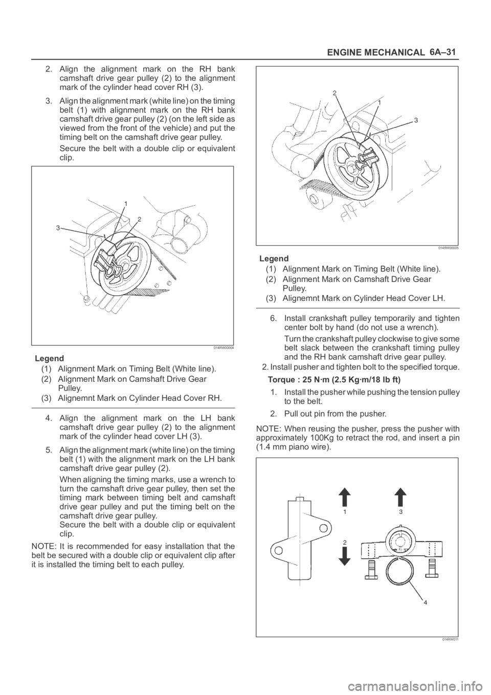
2. Align the alignment mark on the RH bank
camshaft drive gear pulley (2) to the alignment
mark of the cylinder head cover RH (3).
3. Align the alignment mark (white line) on the timing
belt (1) with alignment mark on the RH bank
camshaft drive gear pulley (2) (on the left side as
viewed from the front of the vehicle) and put the
timing belt on the camshaft drive gear pulley.
Secure the belt with a double clip or equivalent
clip.
014RW00004
Legend
(1) Alignment Mark on Timing Belt (White line).
(2) Alignment Mark on Camshaft Drive Gear
Pulley.
(3) Alignemnt Mark on Cylinder Head Cover RH.
4. Align the alignment mark on the LH bank
camshaft drive gear pulley (2) to the alignment
mark of the cylinder head cover LH (3).
5. Align the alignment mark (white line) on the timing
belt (1) with the alignment mark on the LH bank
camshaft drive gear pulley (2).
When aligning the timing marks, use a wrench to
turn the camshaft drive gear pulley, then set the
timing mark between timing belt and camshaft
drive gear pulley and put the timing belt on the
camshaft drive gear pulley.
Secure the belt with a double clip or equivalent
clip.
NOTE: It is recommended for easy installation that the
belt be secured with a double clip or equivalent clip after
it is installed the timing belt to each pulley.
014RW00005
Legend
(1) Alignment Mark on Timing Belt (White line).
(2) Alignment Mark on Camshaft Drive Gear
Pulley.
(3) Alignemnt Mark on Cylinder Head Cover LH.
6. Install crankshaft pulley temporarily and tighten
center bolt by hand (do not use a wrench).
Turn the crankshaft pulley clockwise to give some
belt slack between the crankshaft timing pulley
and the RH bank camshaft drive gear pulley.
2. Install pusher and tighten bolt to the specified torque.
Torque : 25 Nꞏm (2.5 Kgꞏm/18 lb ft)
1. Install the pusher while pushing the tension pulley
to the belt.
2. Pull out pin from the pusher.
NOTE: When reusing the pusher, press the pusher with
approximately 100Kg to retract the rod, and insert a pin
(1.4 mm piano wire).
014RW011