Page 5278 of 6000
ENGINE MECHANICAL 6A – 5
Charging System
Model (HITACHI) LR160-734B LR170 – 760 LR190 – 750B
Rated voltage V 12
Rated output A 60 70 90
Rotation direction
Clockwise
(As viewed from pulled)
Pulley effective diameter mm (in) 60 (2.36) 69 (2.72)
Weight N (kg/lb) 41 (4.2/9.3) 52 (5.3/11.7)
Page 5282 of 6000

ENGINE MECHANICAL 6A – 9
SERVICING
Servicing refers to general maintenance procedures to
be performed by qualified service personnel.
MODEL IDENTIFICATION
Engine Serial Number
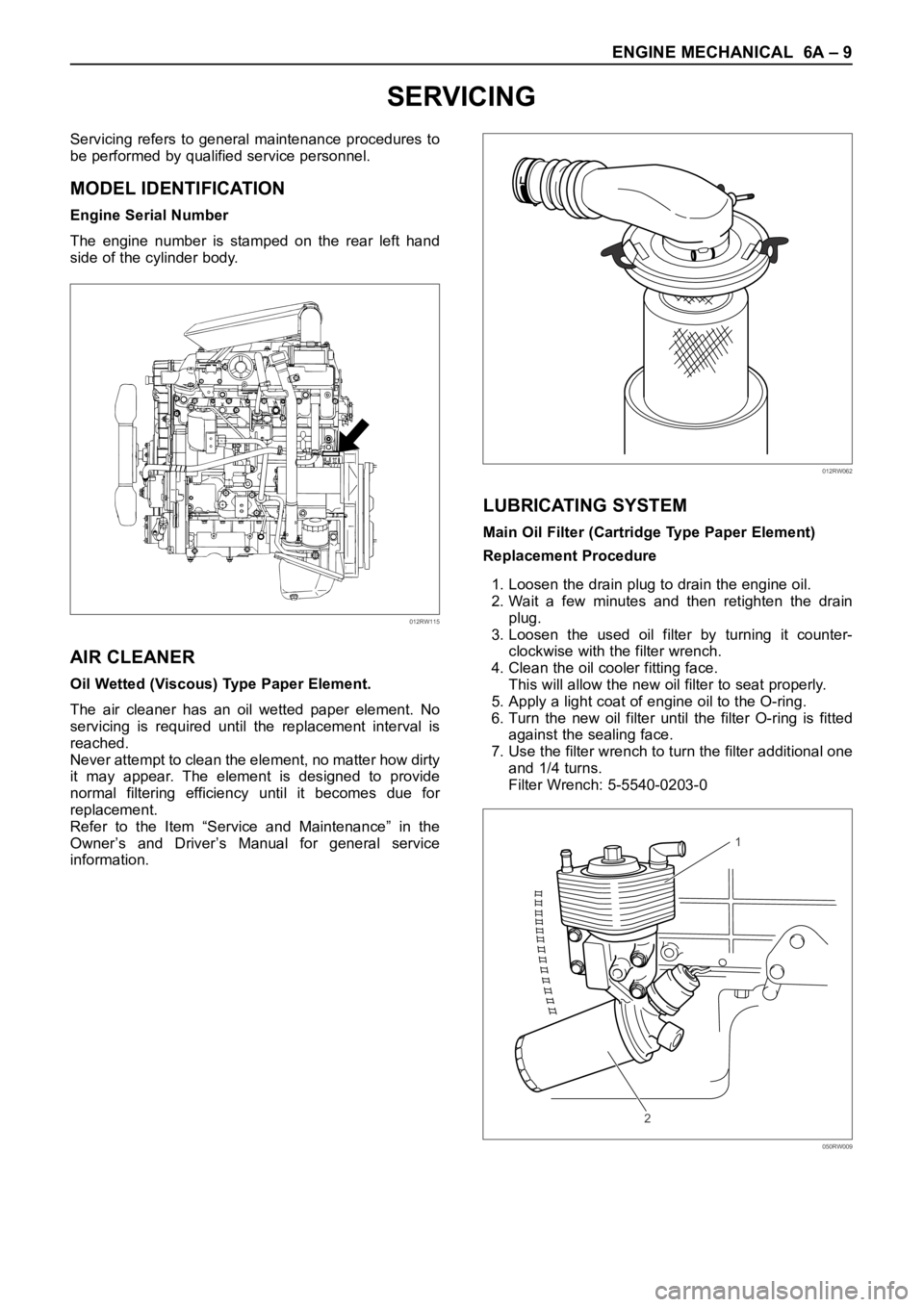
The engine number is stamped on the rear left hand
side of the cylinder body.
AIR CLEANER
Oil Wetted (Viscous) Type Paper Element.
The air cleaner has an oil wetted paper element. No
servicing is required until the replacement interval is
reached.
Never attempt to clean the element, no matter how dirty
it may appear. The element is designed to provide
normal filtering efficiency until it becomes due for
replacement.
Refer to the Item “Service and Maintenance” in the
Owner’s and Driver’s Manual for general service
information.
LUBRICATING SYSTEM
Main Oil Filter (Cartridge Type Paper Element)
Replacement Procedure
1. Loosen the drain plug to drain the engine oil.
2. Wait a few minutes and then retighten the drain
plug.
3. Loosen the used oil filter by turning it counter-
clockwise with the filter wrench.
4. Clean the oil cooler fitting face.
This will allow the new oil filter to seat properly.
5. Apply a light coat of engine oil to the O-ring.
6. Turn the new oil filter until the filter O-ring is fitted
against the sealing face.
7. Use the filter wrench to turn the filter additional one
and 1/4 turns.
Filter Wrench: 5-5540-0203-0
012RW115
012RW062
1
2
050RW009
Page 5283 of 6000

6A – 10 ENGINE MECHANICAL
8. Check the engine oil level and replenish to the
specified level if required.
9. Start the engine and check for oil leakage from the
main oil filter.
FUEL SYSTEM
Fuel filter
Replacement Procedure
1. Loosen the used fuel filter by turning it
counterclockwise with the filter wrench.
Filter Wrench : 5-8840-0203-0
2. Clean the filter cover fitting faces.
This will allow the new fuel filter to seat properly.
3. Apply a light coat of engine oil to the O-ring.
4. Turn the fuel filter until the sealing face comes in
contact with the O-ring.
5. Turn the fuel filter with a filter wrench 2/3 of a turn
until sealed.
Filter Wrench: 5-8840-0203-0Legend
(1) Priming pump
6. Operate the priming pump until the air is discharged
completely from fuel system.
NOTE: The use of an Isuzu genuine fuel filter is
strongly recommended.
COOLING SYSTEM
Coolant Level
Check the coolant level and replenish the radiator
reserve tank as necessary.
If the coolant level falls below the “‘MIN” line, carefully
check the cooling system for leakage. Then add
enough coolant to bring the level up to the “MAX” line.
NOTE: Do not overfill the reserve tank.
012RW112
012RW078
1
012RW111
012RW080
Page 5425 of 6000
6D – 22 ENGINE ELECTRICAL
1. Using a press with a socket wrench attached,
reassemble rotor and rear end cover assembly in
the front cover.2. Install pulley on the rotor.
Secure the pulley directly in the vise between two
copper plates, and tighten nut to the specified
torque.
Torque: 111 Nꞏm (82 lb ft)
066RS022
066RS010
MAIN DATA AND SPECIFICATIONS
General Specifications
Model LR160-734B LR-170-760
Battery voltage V 12
Rated output A 60 70
Direction of rotation Clockwise
(as viewed from pulley side)
Rated rotation speed rpm 5,000
Maximum speed rpm 18,000
Page 5758 of 6000

7A–69 AUTOMATIC TRANSMISSION (4L30–E)
Sprag Unit
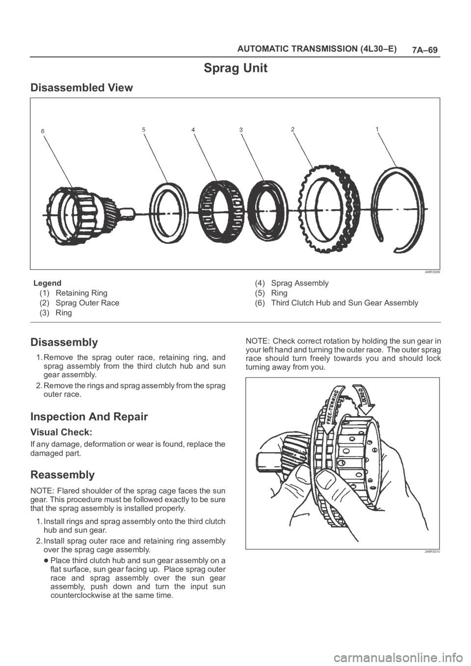
Disassembled View
248RS009
Legend
(1) Retaining Ring
(2) Sprag Outer Race
(3) Ring(4) Sprag Assembly
(5) Ring
(6) Third Clutch Hub and Sun Gear Assembly
Disassembly
1. Remove the sprag outer race, retaining ring, and
sprag assembly from the third clutch hub and sun
gear assembly.
2. Remove the rings and sprag assembly from the sprag
outer race.
Inspection And Repair
Visual Check:
If any damage, deformation or wear is found, replace the
damaged part.
Reassembly
NOTE: Flared shoulder of the sprag cage faces the sun
gear. This procedure must be followed exactly to be sure
that the sprag assembly is installed properly.
1. Install rings and sprag assembly onto the third clutch
hub and sun gear.
2. Install sprag outer race and retaining ring assembly
over the sprag cage assembly.
Place third clutch hub and sun gear assembly on a
flat surface, sun gear facing up. Place sprag outer
race and sprag assembly over the sun gear
assembly, push down and turn the input sun
counterclockwise at the same time. NOTE: Check correct rotation by holding the sun gear in
your left hand and turning the outer race. The outer sprag
race should turn freely towards you and should lock
turning away from you.
248RS010
Page 5896 of 6000
AUTOMATIC TRANSMISSION (AW30-40LE) 7A–115
252L100003
252L100004
252L100005
252L100016
Important operations
Check operation of one-way clutch
Hold the OD direct clutch drum and turn the input shaft.
The input shaft should turn freely clockwise and should lock
counterclockwise.
(1): Free
(2): Lock
1. OD direct clutch assembly
Remove OD direct clutch assembly from OD planetary
gear.
2. Thrust bearing
Then remove thrust bearing with the race from OD direct
clutch drum.
Check piston stroke of OD direct clutch (C-O)
Place the oil pump onto the torque conver ter, and then
place the OD direct clutch assembly onto the oil pump.
Use a dial indicator, measure the OD direct clutch piston
stroke applying and releasing the compressed air (4– 8 kg/
cm
2, 57– 114 psi, 392– 785 kPa) as shown.
mm (in.)
Piston stroke1.85– 2.15
(0.0728– 0.0847)
Page 5906 of 6000
AUTOMATIC TRANSMISSION (AW30-40LE) 7A–125
252L100015
252L100004
252L100003
15. Thrust bearing
Coat the assembled bearing and race with petroleum jelly
and install it with the race side facing downward.
16. OD direct clutch assembly
Align the flukes of discs in the direct clutch .
Install the OD direct clutch assembly onto the OD planetary
gear.
Check operation of one-way clutch.
Hold the OD direct clutch drum and turn the input shaft.
The input shaft should turn freely clockwise and should lock
counterclockwise.
(1): Free
(2): Lock Assembled bearing and race (Reference) mm (in.)
Inside diameter 28.9 (1.138)
Outside diameter 50.2 (1.976)
Page 5935 of 6000
7A–154 AUTOMATIC TRANSMISSION (AW30-40LE)
248RY00051
248RY00052
248RY00053
248RY00054
Important operations
Check operation of No.1 one–way clutch
Hold the planetary sun gear and turn the second brake
hub. The second brake hub should turn freely clockwise
and should lock counterclockwise.
(1) : Free
(2) : Lock
3. Oil seal ring (Metal)
Remove two oil seal rings.
4. Snap ring
Remove the snap ring with snap ring pliers.
INSPECTION AND REPAIR
Check planetary sun gear bushing
Using a dial indicator, measure the inside diameter of the
planetary sun gear bushing.
If the inside diameter is greater than the maximum, replace
the planetary sun gear.mm (in.)
Maximum inside diameter 27.08 (1.0661)