Page 5010 of 6000
6E–353 ENGINE DRIVEABILITY AND EMISSIONS
ILLUSTRATIONTOOL NO.
TOOL NAME
5-8840-0285-0
(J 39200)
High Impedance
Multimeter (Digital
Vo l t m e t e r – D V M )
(1) PCMCIA Card
(2) RS232 Loop Back
Connector
(3) SAE 16/19 Adapter
(4) DLC Cable
(5) TECH–2
5-8840-0607-0
(J 34142-B)
Unpowered Test Light
5-8840-0385-0
(J 35616-A/BT-8637)
Connector Test
Adapter Kit
5-8840-0383-0
(J 26792/BT-7220-1)
Spark Tester
5-8840-0279-0
(J 23738-A)
Vacuum Pump with
Gauge common tool
ILLUSTRATIONTOOL NO.
TOOL NAME
BT-8515
Exhaust Back Pressure
Tester or common tool
5-8840-2640-0
(J 39194-B)
Heated Oxygen Sensor
Wrench
5-8840-0632-0
(J 35689-A)
Terminal Remover
5-8840-0388-0
(J 28742-A)
Weather Pack II
Terminal Remover
5-8840-2635-0
(J 39021-90)
Injector Switch Box
5-8840-2636-0
(J 39021-65)
Injector Test Light
Page 5260 of 6000
ST
ON
OFF
ON
OFF
ON
OFF
ON
OFF
18Km/h
9km/h
ON
OFF
ON
OFF
ON
OFF Starter SW
Starter SW is turned to
“ST” before indicator light
goes out.Starter SW is turned to
“ST” after indicator light
goes out.Starter SW
is left “ON”
Indicator timer
After glow timer
Charge relay
Indicator light
Relay 1
Relay 2Above
Vehicle speed below
t i t i t i
t a t a
t d t d t d t d
Glow plug
temperature
0t 0t 0t
: Indicator light “ON” time
: Rapid after glow (Delay timer) time
: After glow time
ti
td
ta
(For broken lines,
water temperature
is 70
C or above)
Page 5282 of 6000

ENGINE MECHANICAL 6A – 9
SERVICING
Servicing refers to general maintenance procedures to
be performed by qualified service personnel.
MODEL IDENTIFICATION
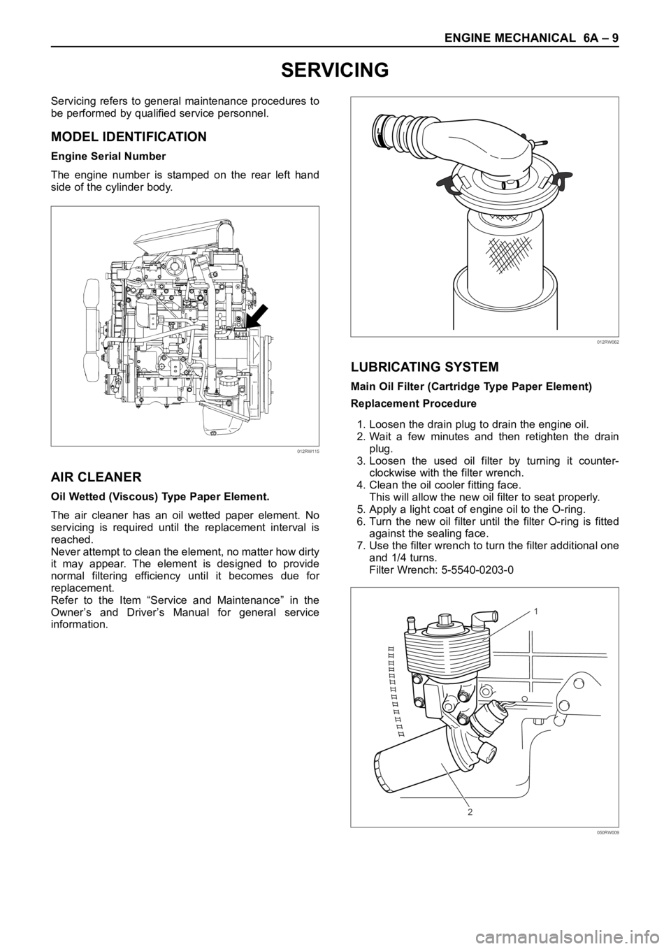
Engine Serial Number
The engine number is stamped on the rear left hand
side of the cylinder body.
AIR CLEANER
Oil Wetted (Viscous) Type Paper Element.
The air cleaner has an oil wetted paper element. No
servicing is required until the replacement interval is
reached.
Never attempt to clean the element, no matter how dirty
it may appear. The element is designed to provide
normal filtering efficiency until it becomes due for
replacement.
Refer to the Item “Service and Maintenance” in the
Owner’s and Driver’s Manual for general service
information.
LUBRICATING SYSTEM
Main Oil Filter (Cartridge Type Paper Element)
Replacement Procedure
1. Loosen the drain plug to drain the engine oil.
2. Wait a few minutes and then retighten the drain
plug.
3. Loosen the used oil filter by turning it counter-
clockwise with the filter wrench.
4. Clean the oil cooler fitting face.
This will allow the new oil filter to seat properly.
5. Apply a light coat of engine oil to the O-ring.
6. Turn the new oil filter until the filter O-ring is fitted
against the sealing face.
7. Use the filter wrench to turn the filter additional one
and 1/4 turns.
Filter Wrench: 5-5540-0203-0
012RW115
012RW062
1
2
050RW009
Page 5283 of 6000

6A – 10 ENGINE MECHANICAL
8. Check the engine oil level and replenish to the
specified level if required.
9. Start the engine and check for oil leakage from the
main oil filter.
FUEL SYSTEM
Fuel filter
Replacement Procedure
1. Loosen the used fuel filter by turning it
counterclockwise with the filter wrench.
Filter Wrench : 5-8840-0203-0
2. Clean the filter cover fitting faces.
This will allow the new fuel filter to seat properly.
3. Apply a light coat of engine oil to the O-ring.
4. Turn the fuel filter until the sealing face comes in
contact with the O-ring.
5. Turn the fuel filter with a filter wrench 2/3 of a turn
until sealed.
Filter Wrench: 5-8840-0203-0Legend
(1) Priming pump
6. Operate the priming pump until the air is discharged
completely from fuel system.
NOTE: The use of an Isuzu genuine fuel filter is
strongly recommended.
COOLING SYSTEM
Coolant Level
Check the coolant level and replenish the radiator
reserve tank as necessary.
If the coolant level falls below the “‘MIN” line, carefully
check the cooling system for leakage. Then add
enough coolant to bring the level up to the “MAX” line.
NOTE: Do not overfill the reserve tank.
012RW112
012RW078
1
012RW111
012RW080
Page 5368 of 6000
ENGINE MECHANICAL 6A – 95
OIL COOLER
1
2
050RW009
Legend
(1) Oil Cooler Assembly
(2) Oil Filter Cartridge
OIL FILTER CARTRIDGE
REMOVAL
1. Place a receptacle beneath the oil filter to contain
the drained oil.
2. Remove the oil filter cartridge using filter wrench.
Filter wrench : 5-8840-0203-0
INSTALLATION
1, Lightly apply oil to the O-ring of oil filter cartridge.
2. Turn the new oil filter cartridge by hand until the
sealing face is fitted against the O-ring.
3. Use the filter wrench to turn the oil filter an
additional one and 1/8 turns.
4. Start the engine and check for oil leakage from oil
filter.
Page 5389 of 6000
6C – 8 ENGINE FUEL
ON-VEHICLE SERVICE
FUEL FILTER ASSEMBLY
REMOVAL
1. Disconnect battery ground cable.
2. Fuel Filler cap
3. Fuel Hose
1) Disconnect fuel hose from filter body.
Plug the hose ends to prevent fuel spillage.
4. Remove the Bolt on Fuel Filter Bracket
5. Remove Fuel Filter Assembly
INSTALLATION
1. Install the fuel filter assembly
2. Tighten the Fuel Filter Bracket Fixing Bolt
3. Fuel Hose
1) Connect hoses to filter body.
4. Fuel Filler Cap
1) Connect the battery ground cable.
2) Feed fuel to the fuel pump by priming, and bleed
the air from fuel system.
FUEL FILTER CARTRIDGE
DISASSEMBLY
1. Drain fuel completely from the fuel filter.
2. Protect the filter body with cloth and lightly grip with
a vise.
3. Remove the cartridge using a filter wrench.
Filter wrench: 5-8840-0203-0
1
Legend
(1) Priming Pump
012RW111
012RW112
Page 5390 of 6000

ENGINE FUEL 6C – 9
REASSEMBLY
1. Clean the cartridge mounting surface of the filter
body so that the cartridge can be secured.
Apply engine oil thinly to new cartridge O-ring.
2. To facilitate bleeding, fill the new cartridge with light
oil.
3. Tighten the cartridge until O-ring comes in contact
with the seal, taking care not to spill the light oil.
4. Retighten 1/3 – 2/3 using a filter wrench.
Filter wrench: 5-8840-0203-0
Bleeding
1. Loosen air bleeding plug.
2. Operate priming pump to bleed the air in the fuel
line.
3. Operate the priming pump until the fuel is overflow
from air bleeding plug.
4. Tighten the air bleeding plug.
5. Start the engine, and if it is not started in 10
seconds or less, repeat the bleeding steps.
6. Make sure of no fuel leakage, and tighten the
priming pump.
Legend
(1) Priming Pump
NOTE: In comparison with the conventional engine,
the capacity of fuel passage in the 4JX1 engine is
larger. It takes the priming pump more time to fill the
engine with fuel.
012RW078
1
012RW111
Page 5404 of 6000

ENGINE ELECTRICAL 6D – 1
ENGINE ELECTRICAL
CONTENTS
Battery . . . . . . . . . . . . . . . . . . . . . . . . . . . . 6D–1
General Description . . . . . . . . . . . . . . . . 6D–1
Diagnosis . . . . . . . . . . . . . . . . . . . . . . . . 6D–1
On Vehicle Service . . . . . . . . . . . . . . . . . 6D–3
Main Data and Specification . . . . . . . . . . 6D–4
Starting System . . . . . . . . . . . . . . . . . . . . . 6D–5
General Description . . . . . . . . . . . . . . . . 6D–5
On Vehicle Service . . . . . . . . . . . . . . . . . 6D–7
Starter . . . . . . . . . . . . . . . . . . . . . . . . . . 6D–7
Unit Repair . . . . . . . . . . . . . . . . . . . . . . . 6D–8Charging System . . . . . . . . . . . . . . . . . . . . 6D–15
General Description . . . . . . . . . . . . . . . . 6D–15
Diagnosis . . . . . . . . . . . . . . . . . . . . . . . . 6D–16
Unit Repair . . . . . . . . . . . . . . . . . . . . . . . 6D–17
Main Data and Specification . . . . . . . . . . 6D–22
QOS4 Preheating System . . . . . . . . . . . . . . 6D–23
General Description . . . . . . . . . . . . . . . . 6D–23
System Diagram . . . . . . . . . . . . . . . . . . . 6D–23
Inspection of QOS4 System Operation . . 6D–24
BATTERY
GENERAL DESCRIPTION
DIAGNOSIS
There are six battery fluid caps at the top of the battery.
These are covered by a paper label.
The battery is completely sealed except for the six
small vent holes at the side. These vent holes permit
the escape of small amounts of gas generated by the
battery.
This type of battery has the following advantages over
conventional batteries:1. There is no need to add water during the entire
service life of the battery.
2. The battery protects itself against overcharging.
The battery will refuse to accept an excessive
charge.
(A conventional battery will accept an excessive
charge, resulting in gassing and loss of battery
fluid.)
3. The battery is much less vulnerable to self-
discharge than a conventional type battery.
1. VISUAL INSPECTION (Step 1)
Inspect the battery for obvious physical damage, such
as a cracked or broken case, which would permit
electrolyte loss.
Replace the battery if obvious physical damage is
discovered during inspection.
Check for any other physical damage and correct it as
necessary. If not, proceed to Step 2.
2. HYDROMETER CHECK (Step 2)
There is a built-in hydrometer (Charge test indicator) at
the top of the battery. It is designed to be used during
diagnostic procedures.
Before trying to read the hydrometer, carefully clean the
upper battery surface.
If your work area is poorly lit, additional light may be
necessary to read the hydrometer.
a. BLUE RING OR DOT VISIBLE – Go to Step 4.
b. BLUE RING OR DOT NOT VISIBLE – Go to
Step 3.3. FLUID LEVEL CHECK (Step 3)
The fluid level should be between the upper level line
and lower level line on side of the battery.
a. CORRECT FLUID LEVEL – Charge the battery.
b. BELOW LOWER LEVEL – Replace battery.
4. VOLTAGE CHECK (Step 4)
(1) Put voltmeter test leads to battery terminals.
a. VOLTAGE IS 12.4V OR ABOVE – Go to Step 5.
b. VOLTAGE IS UNDER 12.4V – Go to procedure
(2) below.
(2) Determine fast charge amperage from
specification. (See Main Data and Specifications in
this section.)
Fast charge battery for 30 minutes at amperage
rate no higher than specified value.
Take voltage and amperage readings after charge.
a. VOLTAGE IS ABOVE 16V AT BELOW 1/3 OF
AMPERAGE RATE – Replace battery.