1998 OPEL FRONTERA light
[x] Cancel search: lightPage 4919 of 6000
6E–262
ENGINE DRIVEABILITY AND EMISSIONS
Symptom Diagnosis
Preliminary Checks
Before using this section, perform the “On-Board
Diagnostic (OBD) System Check” and verify all of the
following items:
The powertrain control module (PCM) and malfunction
indicator lamp (MIL) (Service Engine Soon lamp) are
operating correctly.
There are no DTC(s) stored.
Tech 2 data is within normal operating range. Refer to
Typical Scan Data Values.
Verify the customer complaint and locate the correct
symptom in the table of contents. Perform the
procedure included in the symptom chart.
Visual/Physical Check
Several of the symptom procedures call for a careful
visual/physical check. This can lead to correcting a
problem without further checks and can save valuable
time.
This check should include the following items:
PCM grounds for cleanliness, tightness and proper
location.
Vacuum hoses for splits, kinks, and proper
connections, as shown on the “Vehicle Emission
Control Information” label. Check thoroughly for any
type of leak or restriction.
Air intake ducts for collapsed or damaged areas.
Air leaks at throttle body mounting area, mass air flow
(MAF) sensor and intake manifold sealing surfaces.
Ignition wires for cracking, hardness, and carbon
tracking.
Wiring for proper connections, pinches and cuts.
Intermittents
IMPORTANT:An intermittent problem may or may not
turn on the malfunction indicator lamp (MIL) or store a
DTC. DO NOT use the Diagnostic Trouble Code (DTC)
charts for intermittent problems. The fault must be
present to locate the problem.
Most intermittent problems are caused by faulty electrical
connections or wiring. Perform a careful visual/physical
check for the following conditions:
Poor mating of the connector halves or a terminal not
fully seated in the connector (backed out).
Improperly formed or damaged terminal.
All connector terminals in the problem circuit should be
carefully checked for proper contact tension.
Poor terminal-to-wire connection. This requires
removing the terminal from the connector body to
check.
Road test the vehicle with a J 39200 Digital Multimeter
connected to a suspected circuit. An abnormal voltage
when the malfunction occurs is a good indication that
there is a fault in the circuit being monitored.
Use Tech 2 to help detect intermittent conditions. Tech 2s
have several features that can be used to locate anintermittent condition. Use the following feature to find
intermittent faults:
Using Tech 2’s “Freeze Frame” buffer or “Failure
Records” buffer can aid in locating an intermittent
condition. Review and record the information in the
freeze frame or failure record associated with the
intermittent DTC being diagnosed. The vehicle can be
driven within the conditions that were present when the
DTC originally set.
To check for loss of diagnostic code memory, disconnect
the MAP sensor and idle the engine until the MIL (Service
Engine Soon lamp) comes on. DTC P0107 should be
stored and kept in memory when the ignition is turned
“OFF.” If not, the PCM is faulty. When this test is
completed, make sure that you clear the DTC P0107 from
memory.
An intermittent MIL (Service Engine Soon lamp) with no
stored DTC may be caused by the following:
Ignition coil shorted to ground and arcing at ignition
wires or plugs.
MIL (Service Engine Soon lamp) wire to PCM shorted
to ground.
Poor PCM grounds. Refer to the PCM wiring
diagrams.
Check for improper installation of electrical options such
as lights, cellular phones, etc. Route ignition coil wiring
away from the ignition coils. Check all wires from the
PCM to the ignition coil for poor connections.
Check for an open diode across the A/C compressor
clutch and check for other open diodes (refer to wiring
diagrams in
Electrical Diagnosis).
If problem has not been found, refer to
PCM Connector
Symptom
tables.
Page 4955 of 6000
6E–298
ENGINE DRIVEABILITY AND EMISSIONS
4. Remove the MAP sensor from the mounting bracket.
055RW002
Installation Procedure
1. Install the MAP sensor in the mounting bracket.
055RW002
2. Install the mounting bracket retaining bolt on the
common chamber.
3. Connect the MAP electrical connector.
055RW005
4. Connect the negative battery cable.
Malfunction Indicator Lamp
(MIL)
Removal and Installation Procedure
Refer to Warning light bulb, indicator light valve,
illumination light bulb, A/T indicator light bulb in Meter and
Gauge.
Powertrain Control Module
(PCM)
Service Precaution
NOTE: To prevent possible electrostatic discharge
damage to the PCM, do not touch the connector pins or
soldered components on the circuit board.
Electrostatic Discharge (ESD)
Damage
Electronic components used in the control systems are
often designed to carry very low voltage. Electronic
components are susceptible to damage caused by
electrostatic discharge. Less than 100 volts of static
electricity can cause damage to some electronic
components. By comparison, it takes as much as 4,000
volts for a person to even feel the zap of a static
discharge.
There are several ways for a person to become statically
charged. The most common methods of charging are by
friction and by induction. An example of charging by
friction is a person sliding across a car seat.
Charging by induction occurs when a person with well
insulated shoes stands near a highly charged object and
momentarily touches ground. Charges of the same
polarity are drained off leaving the person highly charged
with the opposite polarity. Static charges can cause
Page 4959 of 6000
6E–302
ENGINE DRIVEABILITY AND EMISSIONS
2. Connect the TP electrical connector.
3. Install the negative battery cable.
Vehicle Speed Sensor (VSS)
Removal Procedure
CAUTION: The VSS is located on the right side of
the transfer case just ahead of the rear propeller
shaft and very close to the exhaust pipes. Be sure
that the exhaust pipes are cool enough to touch
before trying to remove the VSS. If the pipes are hot,
you could be burned.
1. Disconnect the negative battery cable.
2. Disconnect the VSS electrical connector.
TS23748
3. Remove the bolt and the clamp securing the VSS in
place.
IMPORTANT:H a v e a c o n t a i n e r r e a d y t o c a t c h a n y f l u i d
that leaks out when the VSS is removed from the transfer
case.
TS23780
4. Remove the VSS from the transfer case by wiggling it
slightly and pulling it straight out.
Inspection Procedure
1. Inspect the electrical connector for signs of corrosion
or warping. Replace the VSS if the electrical
connector is corroded or warped.
2. Inspect the VSS driven gear for chips, breaks, or worn
condition. Replace the VSS if the driven gear is
chipped, broken or worn.
3. Inspect the O-ring for wear, nicks, tears, or
looseness. Replace the O-ring if necessary.
Installation Procedure
1. Install the VSS in the transfer case with the notch for
the connector facing the rear.
2. Secure the VSS in place with the clamp and the bolt.
Tighten
Tighten the bolt to 16 Nꞏm (12 lb ft.).
TS23780
3. Connect the VSS electrical connector.
TS23748
Page 4994 of 6000
6E–337 ENGINE DRIVEABILITY AND EMISSIONS
0018
Knock Sensor
Insufficient gasoline octane levels may cause detonation
in some engines. Detonation is an uncontrolled explosion
(burn) in the combustion chamber. This uncontrolled
explosion results from a flame front opposite that of the
normal flame front produced by the spark plug. The
rattling sound normally associated with detonation is the
result of two or more opposing pressures (flame fronts)
colliding within the combustion chamber. Light
detonation is sometimes considered normal, but heavy
detonation could result in engine damage.
A knock sensor system is used to control detonation. This
system is designed to retard spark timing up to 20
degrees to reduce detonation in the engine. This allows
the engine to use maximum spark advance to improve
driveability and fuel economy.
The knock sensor system has two major components:
The knock sensor (KS) module.
The knock sensor.
The knock sensor, mounted in the engine block near the
cylinders, detects abnormal vibration in the engine. The
sensor produces an AC output signal of about 10
millivolts. The signal amplitude and frequency are
dependent on the amount of knock being experienced.
The signal voltage increases with the severity of the
knock. This signal voltage is input to the PCM. The PCM
then retards the ignition control (IC) spark timing based
on the KS signal being received.
The PCM determines whether knock is occurring by
comparing the signal level on the KS circuit with the
voltage level on the noise channel. The noise channel
allows the PCM to reject any false knock signal by
indicating the amount of normal engine mechanical noise
present. Normal engine noise varies depending on the
engine speed and load. If the voltage level on the KS
noise channel circuit is below the range considered
normal, DTC P0327 will set, indicating a fault in the KScircuit or the knock sensor. If the PCM determines that an
abnormal minimum or maximum noise level is being
experienced, DTC P0325 will set.
The PCM contains a knock sensor (KS) module. The KS
module contains the circuitry which allows the PCM to
utilize the KS signal and diagnose the KS sensor and the
KS circuitry. If the KS module is missing or faulty, a
continuous knock condition will be indicated, and the
PCM will set DTC P0325.
Although it is a plug-in device, the KS module is not
replaceable. If the KS module is faulty, the entire PCM
must be replaced.
0009
Linear Exhaust Gas Recirculation (EGR)
Control
The PCM monitors the exhaust gas recirculation (EGR)
actual position and adjusts the pintle position accordingly.
The PCM uses information from the following sensors to
control the pintle position:
Engine coolant temperature (ECT) sensor.
Throttle position (TP) sensor.
Mass air flow (MAF) sensor.
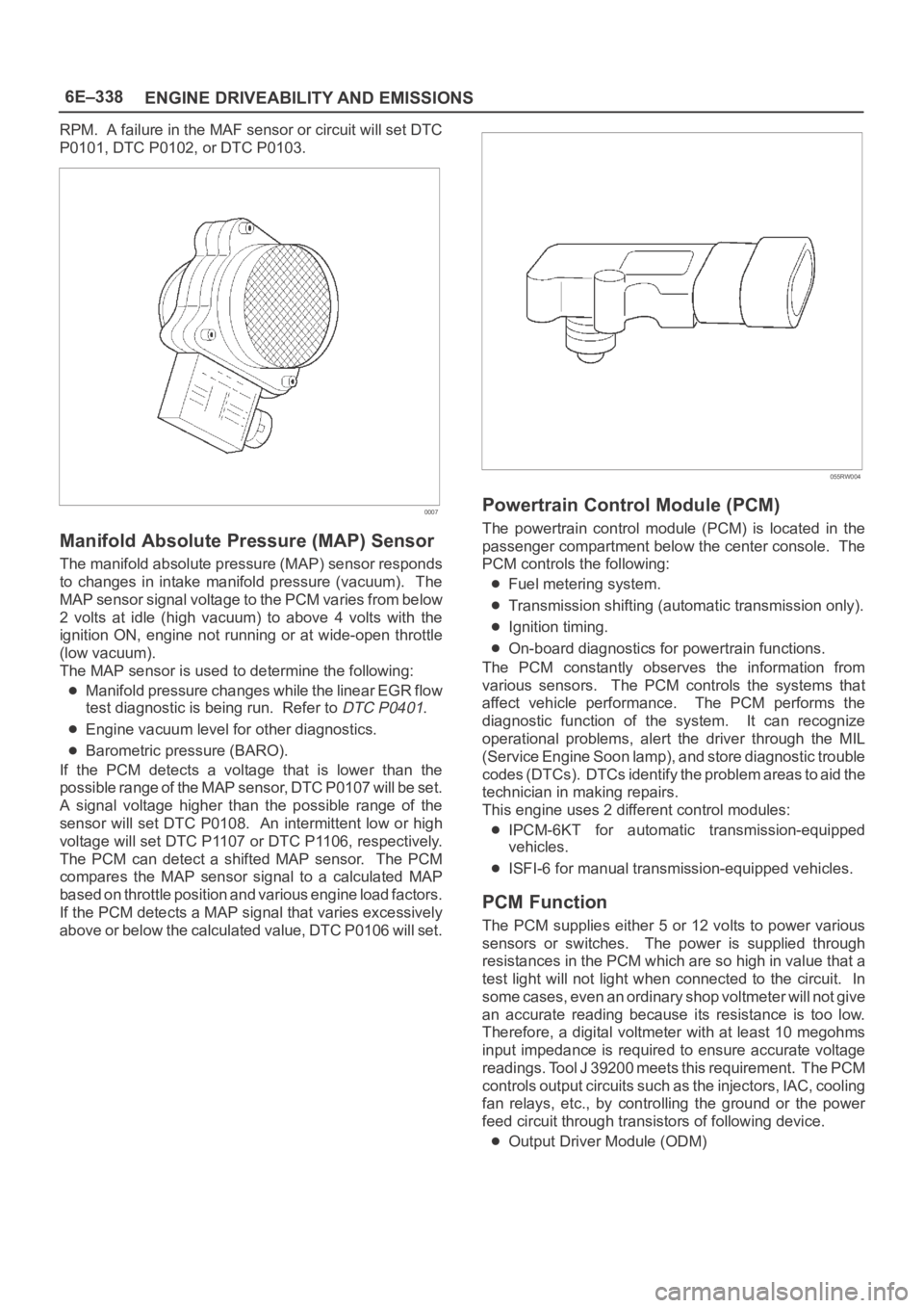
Mass Air Flow (MAF) Sensor
The mass air flow (MAF) sensor measures the difference
between the volume and the quantity of air that enters the
engine. “Volume” means the size of the space to be filled.
“Quantity” means the number of air molecules that will fit
into the space. This information is important to the PCM
because heavier, denser air will hold more fuel than
lighter, thinner air. The PCM adjusts the air/fuel ratio as
needed depending on the MAF value. Tech 2 reads the
MAF value and displays it in terms of grams per second
(gm/s). At idle, Tech 2 should read between 4-7 gm/s on a
fully warmed up engine. Values should change quickly on
acceleration. Values should remain stable at any given
Page 4995 of 6000
6E–338
ENGINE DRIVEABILITY AND EMISSIONS
RPM. A failure in the MAF sensor or circuit will set DTC
P0101, DTC P0102, or DTC P0103.
0007
Manifold Absolute Pressure (MAP) Sensor
The manifold absolute pressure (MAP) sensor responds
to changes in intake manifold pressure (vacuum). The
MAP sensor signal voltage to the PCM varies from below
2 volts at idle (high vacuum) to above 4 volts with the
ignition ON, engine not running or at wide-open throttle
(low vacuum).
The MAP sensor is used to determine the following:
Manifold pressure changes while the linear EGR flow
test diagnostic is being run. Refer to
DTC P0401.
Engine vacuum level for other diagnostics.
Barometric pressure (BARO).
If the PCM detects a voltage that is lower than the
possible range of the MAP sensor, DTC P0107 will be set.
A signal voltage higher than the possible range of the
sensor will set DTC P0108. An intermittent low or high
voltage will set DTC P1107 or DTC P1106, respectively.
The PCM can detect a shifted MAP sensor. The PCM
compares the MAP sensor signal to a calculated MAP
based on throttle position and various engine load factors.
If the PCM detects a MAP signal that varies excessively
above or below the calculated value, DTC P0106 will set.
055RW004
Powertrain Control Module (PCM)
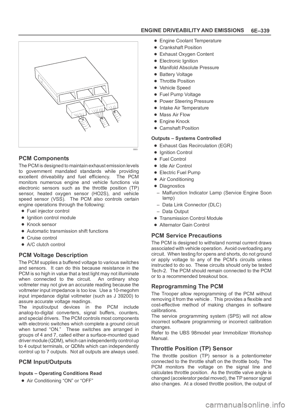
The powertrain control module (PCM) is located in the
passenger compartment below the center console. The
PCM controls the following:
Fuel metering system.
Transmission shifting (automatic transmission only).
Ignition timing.
On-board diagnostics for powertrain functions.
The PCM constantly observes the information from
various sensors. The PCM controls the systems that
affect vehicle performance. The PCM performs the
diagnostic function of the system. It can recognize
operational problems, alert the driver through the MIL
(Service Engine Soon lamp), and store diagnostic trouble
codes (DTCs). DTCs identify the problem areas to aid the
technician in making repairs.
This engine uses 2 different control modules:
IPCM-6KT for automatic transmission-equipped
vehicles.
ISFI-6 for manual transmission-equipped vehicles.
PCM Function
The PCM supplies either 5 or 12 volts to power various
sensors or switches. The power is supplied through
resistances in the PCM which are so high in value that a
test light will not light when connected to the circuit. In
some cases, even an ordinary shop voltmeter will not give
an accurate reading because its resistance is too low.
Therefore, a digital voltmeter with at least 10 megohms
input impedance is required to ensure accurate voltage
readings. Tool J 39200 meets this requirement. The PCM
controls output circuits such as the injectors, IAC, cooling
fan relays, etc., by controlling the ground or the power
feed circuit through transistors of following device.
Output Driver Module (ODM)
Page 4996 of 6000
6E–339 ENGINE DRIVEABILITY AND EMISSIONS
0005
PCM Components
The PCM is designed to maintain exhaust emission levels
to government mandated standards while providing
excellent driveability and fuel efficiency. The PCM
monitors numerous engine and vehicle functions via
electronic sensors such as the throttle position (TP)
sensor, heated oxygen sensor (HO2S), and vehicle
speed sensor (VSS). The PCM also controls certain
engine operations through the following:
Fuel injector control
Ignition control module
Knock sensor
Automatic transmission shift functions
Cruise control
A/C clutch control
PCM Voltage Description
The PCM supplies a buffered voltage to various switches
and sensors. It can do this because resistance in the
PCM is so high in value that a test light may not illuminate
when connected to the circuit. An ordinary shop
voltmeter may not give an accurate reading because the
voltmeter input impedance is too low. Use a 10-megohm
input impedance digital voltmeter (such as J 39200) to
assure accurate voltage readings.
The input/output devices in the PCM include
analog-to-digital converters, signal buffers, counters,
and special drivers. The PCM controls most components
with electronic switches which complete a ground circuit
when turned “ON.” These switches are arranged in
groups of 4 and 7, called either a surface-mounted quad
driver module (QDM), which can independently control up
to 4 output terminals, or QDMs which can independently
control up to 7 outputs. Not all outputs are always used.
PCM Input/Outputs
Inputs – Operating Conditions Read
Air Conditioning “ON” or “OFF”
Engine Coolant Temperature
Crankshaft Position
Exhaust Oxygen Content
Electronic Ignition
Manifold Absolute Pressure
Battery Voltage
Throttle Position
Vehicle Speed
Fuel Pump Voltage
Power Steering Pressure
Intake Air Temperature
Mass Air Flow
Engine Knock
Camshaft Position
Outputs – Systems Controlled
Exhaust Gas Recirculation (EGR)
Ignition Control
Fuel Control
Idle Air Control
Electric Fuel Pump
Air Conditioning
Diagnostics
– Malfunction Indicator Lamp (Service Engine Soon
lamp)
– Data Link Connector (DLC)
– Data Output
Transmission Control Module
Alternator Gain Control
PCM Service Precautions
The PCM is designed to withstand normal current draws
associated with vehicle operation. Avoid overloading any
circuit. When testing for opens and shorts, do not ground
or apply voltage to any of the PCM’s circuits unless
instructed to do so. These circuits should only be tested
Tech-2. The PCM should remain connected to the PCM
or to a recommended breakout box.
Reprogramming The PCM
The Trooper allow reprogramming of the PCM without
removing it from the vehicle . This provides a flexible and
cost-effective method of making changes in software
calibrations.
The service programming system (SPS) will not allow
incorrect software programming or incorrect calibration
changes.
Refer to the UBS 98model year Immobilizer Workshop
Manual.
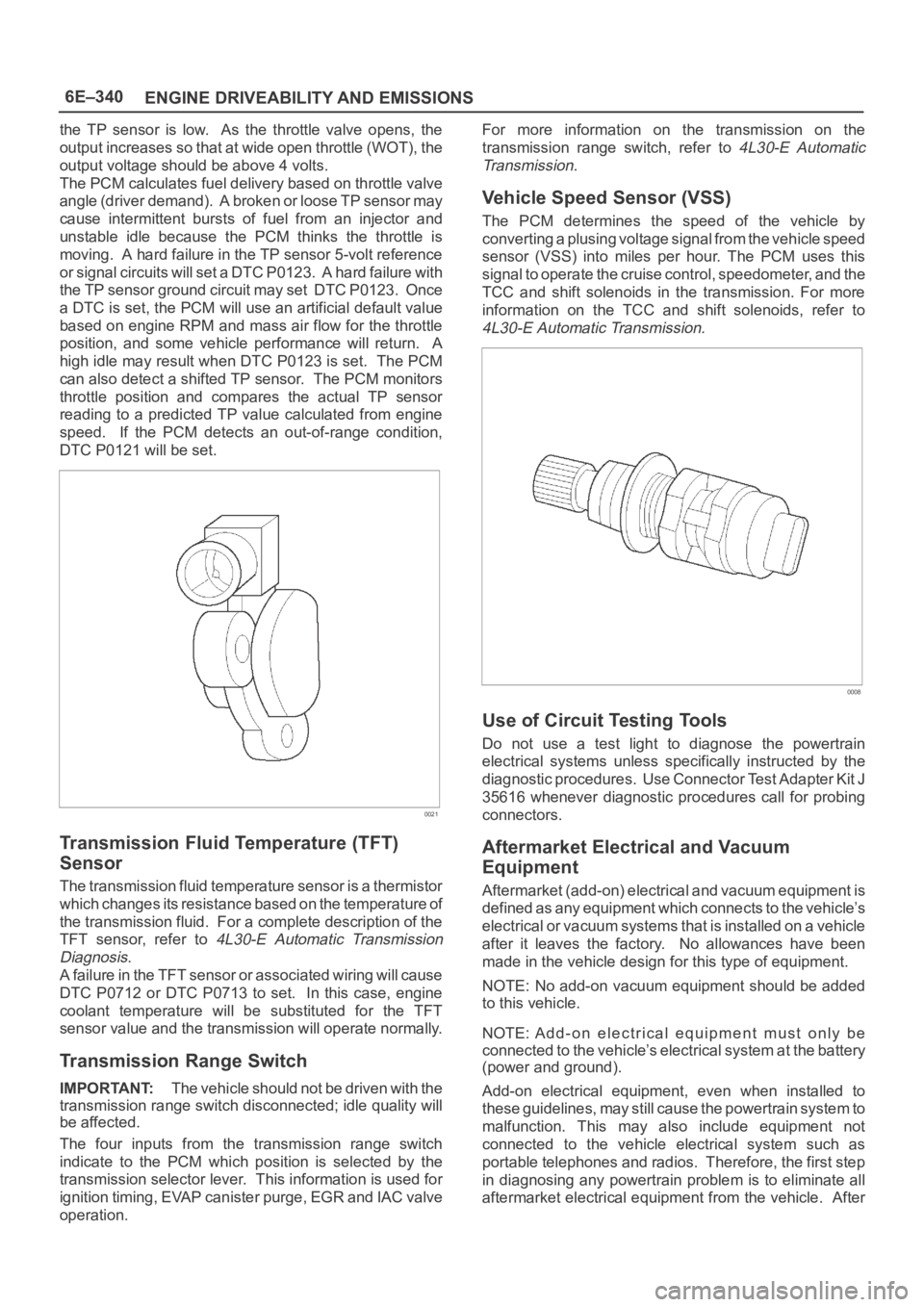
Throttle Position (TP) Sensor
The throttle position (TP) sensor is a potentiometer
connected to the throttle shaft on the throttle body. The
PCM monitors the voltage on the signal line and
calculates throttle position. As the throttle valve angle is
changed (accelerator pedal moved), the TP sensor signal
also changes. At a closed throttle position, the output of
Page 4997 of 6000
6E–340
ENGINE DRIVEABILITY AND EMISSIONS
the TP sensor is low. As the throttle valve opens, the
output increases so that at wide open throttle (WOT), the
output voltage should be above 4 volts.
The PCM calculates fuel delivery based on throttle valve
angle (driver demand). A broken or loose TP sensor may
cause intermittent bursts of fuel from an injector and
unstable idle because the PCM thinks the throttle is
moving. A hard failure in the TP sensor 5-volt reference
or signal circuits will set a DTC P0123. A hard failure with
the TP sensor ground circuit may set DTC P0123. Once
a DTC is set, the PCM will use an artificial default value
based on engine RPM and mass air flow for the throttle
position, and some vehicle performance will return. A
high idle may result when DTC P0123 is set. The PCM
can also detect a shifted TP sensor. The PCM monitors
throttle position and compares the actual TP sensor
reading to a predicted TP value calculated from engine
speed. If the PCM detects an out-of-range condition,
DTC P0121 will be set.
0021
Transmission Fluid Temperature (TFT)
Sensor
The transmission fluid temperature sensor is a thermistor
which changes its resistance based on the temperature of
the transmission fluid. For a complete description of the
TFT sensor, refer to
4L30-E Automatic Transmission
Diagnosis
.
A failure in the TFT sensor or associated wiring will cause
DTC P0712 or DTC P0713 to set. In this case, engine
coolant temperature will be substituted for the TFT
sensor value and the transmission will operate normally.
Transmission Range Switch
IMPORTANT:The vehicle should not be driven with the
transmission range switch disconnected; idle quality will
be affected.
The four inputs from the transmission range switch
indicate to the PCM which position is selected by the
transmission selector lever. This information is used for
ignition timing, EVAP canister purge, EGR and IAC valve
operation.For more information on the transmission on the
transmission range switch, refer to
4L30-E Automatic
Transmission
.
Vehicle Speed Sensor (VSS)
The PCM determines the speed of the vehicle by
converting a plusing voltage signal from the vehicle speed
sensor (VSS) into miles per hour. The PCM uses this
signal to operate the cruise control, speedometer, and the
TCC and shift solenoids in the transmission. For more
information on the TCC and shift solenoids, refer to
4L30-E Automatic Transmission.
0008
Use of Circuit Testing Tools
Do not use a test light to diagnose the powertrain
electrical systems unless specifically instructed by the
diagnostic procedures. Use Connector Test Adapter Kit J
35616 whenever diagnostic procedures call for probing
connectors.
Aftermarket Electrical and Vacuum
Equipment
Aftermarket (add-on) electrical and vacuum equipment is
defined as any equipment which connects to the vehicle’s
electrical or vacuum systems that is installed on a vehicle
after it leaves the factory. No allowances have been
made in the vehicle design for this type of equipment.
NOTE: No add-on vacuum equipment should be added
to this vehicle.
NOTE: Add-on electrical equipment must only be
connected to the vehicle’s electrical system at the battery
(power and ground).
Add-on electrical equipment, even when installed to
these guidelines, may still cause the powertrain system to
malfunction. This may also include equipment not
connected to the vehicle electrical system such as
portable telephones and radios. Therefore, the first step
in diagnosing any powertrain problem is to eliminate all
aftermarket electrical equipment from the vehicle. After
Page 5004 of 6000
6E–347 ENGINE DRIVEABILITY AND EMISSIONS
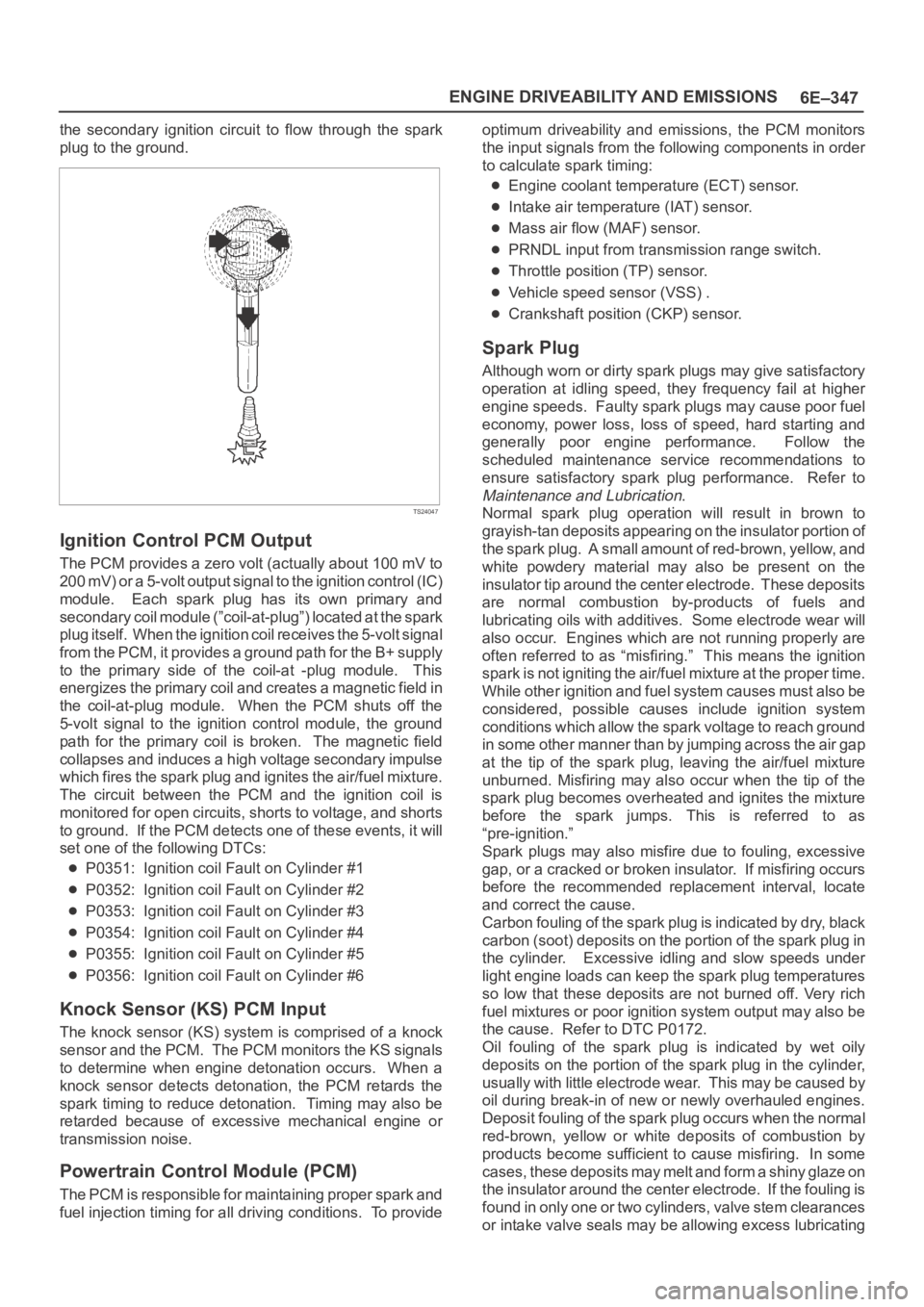
the secondary ignition circuit to flow through the spark
plug to the ground.
TS24047
Ignition Control PCM Output
The PCM provides a zero volt (actually about 100 mV to
200 mV) or a 5-volt output signal to the ignition control (IC)
module. Each spark plug has its own primary and
secondary coil module (”coil-at-plug”) located at the spark
plug itself. When the ignition coil receives the 5-volt signal
from the PCM, it provides a ground path for the B+ supply
to the primary side of the coil-at -plug module. This
energizes the primary coil and creates a magnetic field in
the coil-at-plug module. When the PCM shuts off the
5-volt signal to the ignition control module, the ground
path for the primary coil is broken. The magnetic field
collapses and induces a high voltage secondary impulse
which fires the spark plug and ignites the air/fuel mixture.
The circuit between the PCM and the ignition coil is
monitored for open circuits, shorts to voltage, and shorts
to ground. If the PCM detects one of these events, it will
set one of the following DTCs:
P0351: Ignition coil Fault on Cylinder #1
P0352: Ignition coil Fault on Cylinder #2
P0353: Ignition coil Fault on Cylinder #3
P0354: Ignition coil Fault on Cylinder #4
P0355: Ignition coil Fault on Cylinder #5
P0356: Ignition coil Fault on Cylinder #6
Knock Sensor (KS) PCM Input
The knock sensor (KS) system is comprised of a knock
sensor and the PCM. The PCM monitors the KS signals
to determine when engine detonation occurs. When a
knock sensor detects detonation, the PCM retards the
spark timing to reduce detonation. Timing may also be
retarded because of excessive mechanical engine or
transmission noise.
Powertrain Control Module (PCM)
The PCM is responsible for maintaining proper spark and
fuel injection timing for all driving conditions. To provideoptimum driveability and emissions, the PCM monitors
the input signals from the following components in order
to calculate spark timing:
Engine coolant temperature (ECT) sensor.
Intake air temperature (IAT) sensor.
Mass air flow (MAF) sensor.
PRNDL input from transmission range switch.
Throttle position (TP) sensor.
Vehicle speed sensor (VSS) .
Crankshaft position (CKP) sensor.
Spark Plug
Although worn or dirty spark plugs may give satisfactory
operation at idling speed, they frequency fail at higher
engine speeds. Faulty spark plugs may cause poor fuel
economy, power loss, loss of speed, hard starting and
generally poor engine performance. Follow the
scheduled maintenance service recommendations to
ensure satisfactory spark plug performance. Refer to
Maintenance and Lubrication.
Normal spark plug operation will result in brown to
grayish-tan deposits appearing on the insulator portion of
the spark plug. A small amount of red-brown, yellow, and
white powdery material may also be present on the
insulator tip around the center electrode. These deposits
are normal combustion by-products of fuels and
lubricating oils with additives. Some electrode wear will
also occur. Engines which are not running properly are
often referred to as “misfiring.” This means the ignition
spark is not igniting the air/fuel mixture at the proper time.
While other ignition and fuel system causes must also be
considered, possible causes include ignition system
conditions which allow the spark voltage to reach ground
in some other manner than by jumping across the air gap
at the tip of the spark plug, leaving the air/fuel mixture
unburned. Misfiring may also occur when the tip of the
spark plug becomes overheated and ignites the mixture
before the spark jumps. This is referred to as
“pre-ignition.”
Spark plugs may also misfire due to fouling, excessive
gap, or a cracked or broken insulator. If misfiring occurs
before the recommended replacement interval, locate
and correct the cause.
Carbon fouling of the spark plug is indicated by dry, black
carbon (soot) deposits on the portion of the spark plug in
the cylinder. Excessive idling and slow speeds under
light engine loads can keep the spark plug temperatures
so low that these deposits are not burned off. Very rich
fuel mixtures or poor ignition system output may also be
the cause. Refer to DTC P0172.
Oil fouling of the spark plug is indicated by wet oily
deposits on the portion of the spark plug in the cylinder,
usually with little electrode wear. This may be caused by
oil during break-in of new or newly overhauled engines.
Deposit fouling of the spark plug occurs when the normal
red-brown, yellow or white deposits of combustion by
products become sufficient to cause misfiring. In some
c a s e s , t h e s e d e p o s i t s m a y m e l t a n d f o r m a s h i n y g l a z e o n
the insulator around the center electrode. If the fouling is
found in only one or two cylinders, valve stem clearances
or intake valve seals may be allowing excess lubricating