1998 OPEL FRONTERA light
[x] Cancel search: lightPage 5500 of 6000
6E–71 4JX1–TC ENGINE DRIVEABILITY AND EMISSIONS
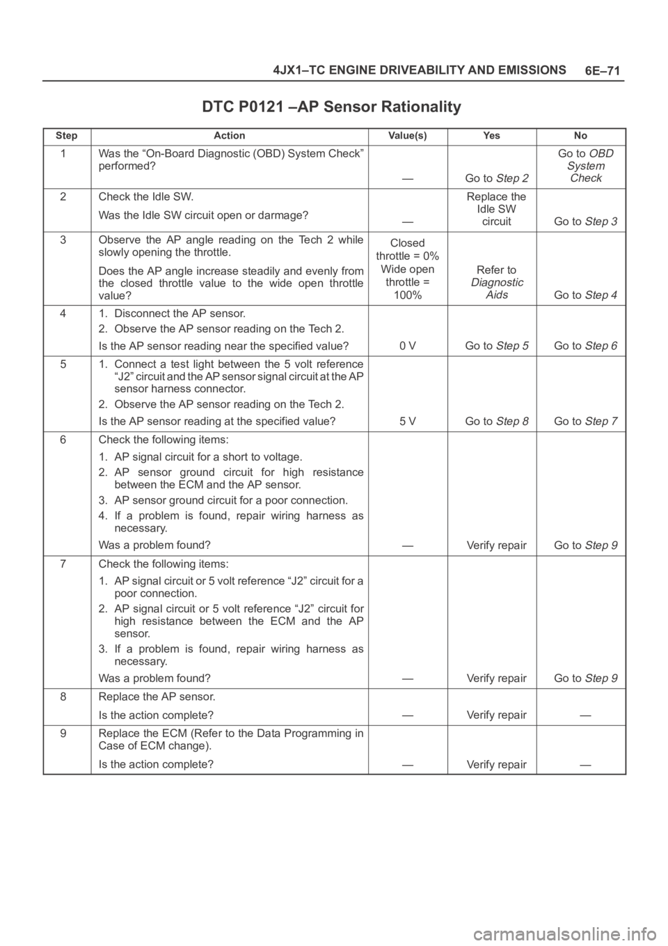
DTC P0121 –AP Sensor Rationality
StepActionVa l u e ( s )Ye sNo
1Was the “On-Board Diagnostic (OBD) System Check”
performed?
—Go to Step 2
Go to OBD
System
Check
2Check the Idle SW.
Was the Idle SW circuit open or darmage?
—
Replace the
Idle SW
circuit
Go to Step 3
3Observe the AP angle reading on the Tech 2 while
slowly opening the throttle.
Does the AP angle increase steadily and evenly from
the closed throttle value to the wide open throttle
value?Closed
throttle = 0%
Wide open
throttle =
100%
Refer to
Diagnostic
Aids
Go to Step 4
41. Disconnect the AP sensor.
2. Observe the AP sensor reading on the Tech 2.
Is the AP sensor reading near the specified value?
0 VGo to Step 5Go to Step 6
51. Connect a test light between the 5 volt reference
“J2” circuit and the AP sensor signal circuit at the AP
sensor harness connector.
2. Observe the AP sensor reading on the Tech 2.
Is the AP sensor reading at the specified value?
5 VGo to Step 8Go to Step 7
6Check the following items:
1. AP signal circuit for a short to voltage.
2. AP sensor ground circuit for high resistance
between the ECM and the AP sensor.
3. AP sensor ground circuit for a poor connection.
4. If a problem is found, repair wiring harness as
necessary.
Was a problem found?
—Verify repairGo to Step 9
7Check the following items:
1. AP signal circuit or 5 volt reference “J2” circuit for a
poor connection.
2. AP signal circuit or 5 volt reference “J2” circuit for
high resistance between the ECM and the AP
sensor.
3. If a problem is found, repair wiring harness as
necessary.
Was a problem found?
—Verify repairGo to Step 9
8Replace the AP sensor.
Is the action complete?
—Verify repair—
9Replace the ECM (Refer to the Data Programming in
Case of ECM change).
Is the action complete?
—Verify repair—
Page 5502 of 6000
6E–73 4JX1–TC ENGINE DRIVEABILITY AND EMISSIONS
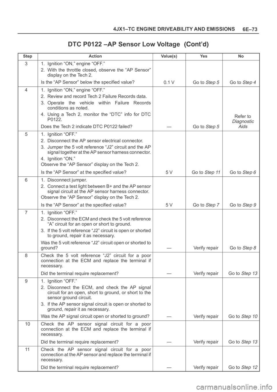
DTC P0122 –AP Sensor Low Voltage
StepNo Ye s Va l u e ( s ) Action
31. Ignition “ON,” engine “OFF.”
2. With the throttle closed, observe the “AP Sensor”
display on the Tech 2.
Is the “AP Sensor” below the specified value?
0.1 VGo to Step 5Go to Step 4
41. Ignition “ON,” engine “OFF.”
2. Review and record Tech 2 Failure Records data.
3. Operate the vehicle within Failure Records
conditions as noted.
4. Using a Tech 2, monitor the “DTC” info for DTC
P0122.
Does the Tech 2 indicate DTC P0122 failed?
—Go to Step 5
Refer to
Diagnostic
Aids
51. Ignition “OFF.”
2. Disconnect the AP sensor electrical connector.
3. Jumper the 5 volt reference “J2” circuit and the AP
signal together at the AP sensor harness connector.
4. Ignition “ON.”
Observe the “AP Sensor” display on the Tech 2.
Is the “AP Sensor” at the specified value?
5 VGo to Step 11Go to Step 6
61. Disconnect jumper.
2. Connect a test light between B+ and the AP sensor
signal circuit at the AP sensor harness connector.
Observe the “AP Sensor” display on the Tech 2.
Is the “AP Sensor” at the specified value?
5 VGo to Step 7Go to Step 9
71. Ignition “OFF.”
2. Disconnect the ECM and check the 5 volt reference
“A” circuit for an open or short to ground.
3. If the 5 volt reference “J2” circuit is open or shorted
to ground, repair it as necessary.
Was the 5 volt reference “J2” circuit open or shorted to
ground?
—Verify repairGo to Step 8
8Check the 5 volt reference “J2” circuit for a poor
connection at the ECM and replace the terminal if
necessary.
Did the terminal require replacement?
—Verify repairGo to Step 13
91. Ignition “OFF.”
2. Disconnect the ECM, and check the AP signal
circuit for an open, short to ground, or short to the
sensor ground circuit.
3. If the AP sensor signal circuit is open or shorted to
ground, repair it as necessary.
Was the AP signal circuit open or shorted to ground?
—Verify repairGo to Step 10
10Check the AP sensor signal circuit for a poor
connection at the ECM and replace the terminal if
necessary.
Did the terminal require replacement?
—Verify repairGo to Step 13
11Check the AP sensor signal circuit for a poor
connection at the AP sensor and replace the terminal if
necessary.
Did the terminal require replacement?
—Verify repairGo to Step 12
Page 5505 of 6000
6E–76
4JX1–TC ENGINE DRIVEABILITY AND EMISSIONS
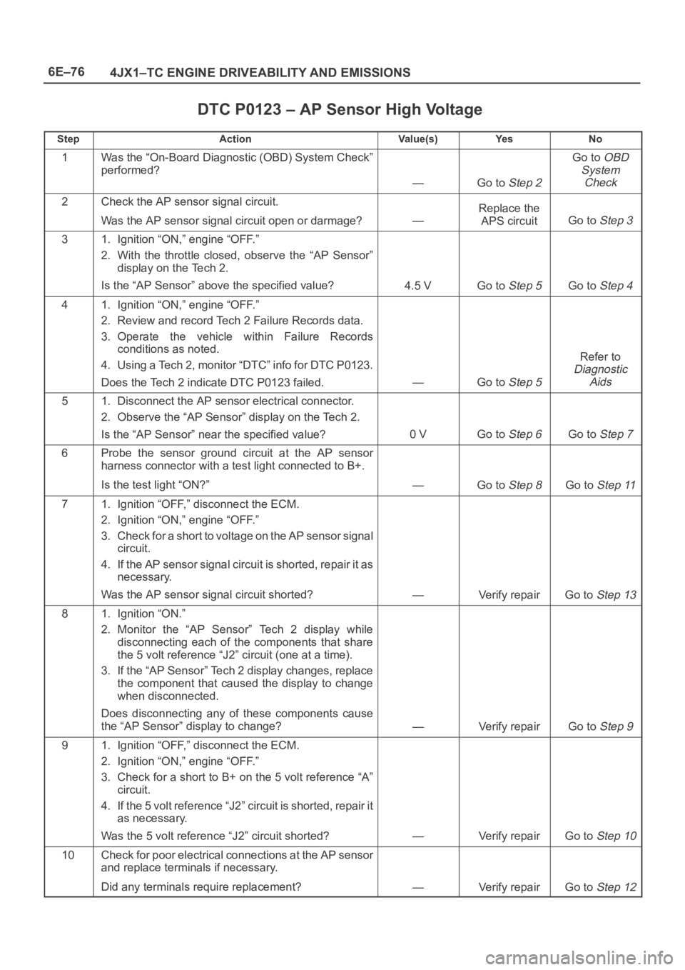
DTC P0123 – AP Sensor High Voltage
StepActionVa l u e ( s )Ye sNo
1Was the “On-Board Diagnostic (OBD) System Check”
performed?
—Go to Step 2
Go to OBD
System
Check
2Check the AP sensor signal circuit.
Was the AP sensor signal circuit open or darmage?
—
Replace the
APS circuit
Go to Step 3
31. Ignition “ON,” engine “OFF.”
2. With the throttle closed, observe the “AP Sensor”
display on the Tech 2.
Is the “AP Sensor” above the specified value?
4.5 VGo to Step 5Go to Step 4
41. Ignition “ON,” engine “OFF.”
2. Review and record Tech 2 Failure Records data.
3. Operate the vehicle within Failure Records
conditions as noted.
4. Using a Tech 2, monitor “DTC” info for DTC P0123.
Does the Tech 2 indicate DTC P0123 failed.
—Go to Step 5
Refer to
Diagnostic
Aids
51. Disconnect the AP sensor electrical connector.
2. Observe the “AP Sensor” display on the Tech 2.
Is the “AP Sensor” near the specified value?
0 VGo to Step 6Go to Step 7
6Probe the sensor ground circuit at the AP sensor
harness connector with a test light connected to B+.
Is the test light “ON?”
—Go to Step 8Go to Step 11
71. Ignition “OFF,” disconnect the ECM.
2. Ignition “ON,” engine “OFF.”
3. Check for a short to voltage on the AP sensor signal
circuit.
4. If the AP sensor signal circuit is shorted, repair it as
necessary.
Was the AP sensor signal circuit shorted?
—Verify repairGo to Step 13
81. Ignition “ON.”
2. Monitor the “AP Sensor” Tech 2 display while
disconnecting each of the components that share
the 5 volt reference “J2” circuit (one at a time).
3. If the “AP Sensor” Tech 2 display changes, replace
the component that caused the display to change
when disconnected.
Does disconnecting any of these components cause
the “AP Sensor” display to change?
—Verify repairGo to Step 9
91. Ignition “OFF,” disconnect the ECM.
2. Ignition “ON,” engine “OFF.”
3. Check for a short to B+ on the 5 volt reference “A”
circuit.
4. If the 5 volt reference “J2” circuit is shorted, repair it
as necessary.
Was the 5 volt reference “J2” circuit shorted?
—Verify repairGo to Step 10
10Check for poor electrical connections at the AP sensor
and replace terminals if necessary.
Did any terminals require replacement?
—Verify repairGo to Step 12
Page 5514 of 6000
6E–85 4JX1–TC ENGINE DRIVEABILITY AND EMISSIONS
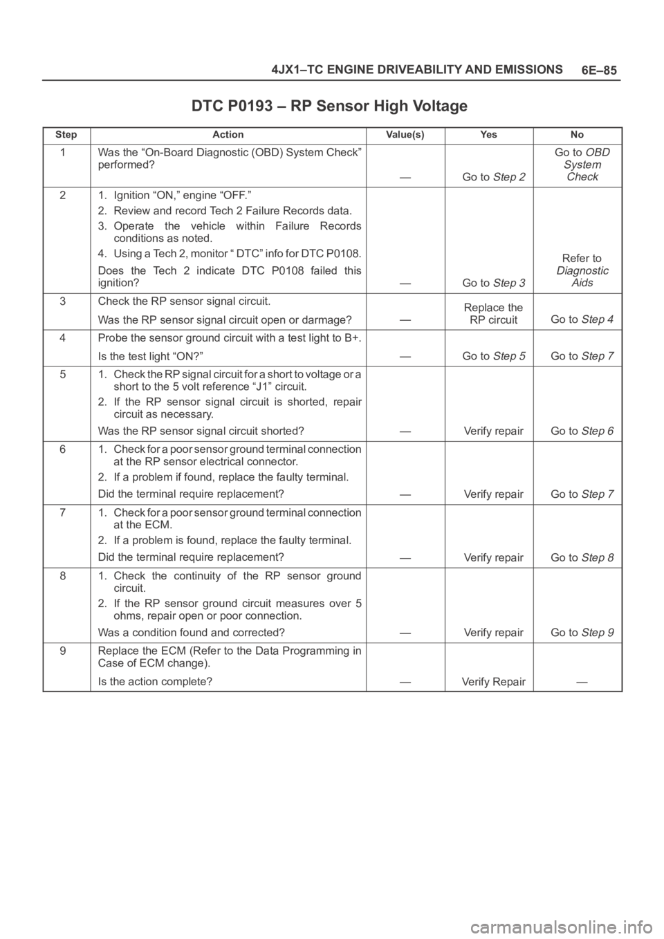
DTC P0193 – RP Sensor High Voltage
StepActionVa l u e ( s )Ye sNo
1Was the “On-Board Diagnostic (OBD) System Check”
performed?
—Go to Step 2
Go to OBD
System
Check
21. Ignition “ON,” engine “OFF.”
2. Review and record Tech 2 Failure Records data.
3. Operate the vehicle within Failure Records
conditions as noted.
4. Using a Tech 2, monitor “ DTC” info for DTC P0108.
Does the Tech 2 indicate DTC P0108 failed this
ignition?
—Go to Step 3
Refer to
Diagnostic
Aids
3Check the RP sensor signal circuit.
Was the RP sensor signal circuit open or darmage?
—
Replace the
RP circuit
Go to Step 4
4Probe the sensor ground circuit with a test light to B+.
Is the test light “ON?”
—Go to Step 5Go to Step 7
51. Check the RP signal circuit for a short to voltage or a
short to the 5 volt reference “J1” circuit.
2. If the RP sensor signal circuit is shorted, repair
circuit as necessary.
Was the RP sensor signal circuit shorted?
—Verify repairGo to Step 6
61. Check for a poor sensor ground terminal connection
at the RP sensor electrical connector.
2. If a problem if found, replace the faulty terminal.
Did the terminal require replacement?
—Verify repairGo to Step 7
71. Check for a poor sensor ground terminal connection
at the ECM.
2. If a problem is found, replace the faulty terminal.
Did the terminal require replacement?
—Verify repairGo to Step 8
81. Check the continuity of the RP sensor ground
circuit.
2. If the RP sensor ground circuit measures over 5
ohms, repair open or poor connection.
Was a condition found and corrected?
—Verify repairGo to Step 9
9Replace the ECM (Refer to the Data Programming in
Case of ECM change).
Is the action complete?
—Verify Repair—
Page 5518 of 6000
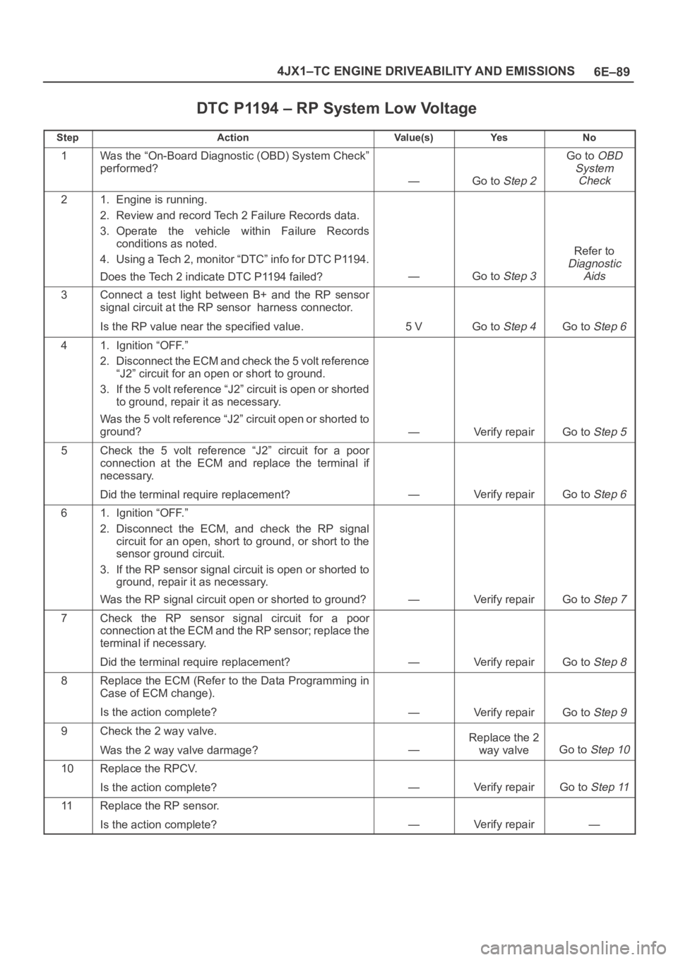
6E–89 4JX1–TC ENGINE DRIVEABILITY AND EMISSIONS
DTC P1194 – RP System Low Voltage
StepActionVa l u e ( s )Ye sNo
1Was the “On-Board Diagnostic (OBD) System Check”
performed?
—Go to Step 2
Go to OBD
System
Check
21. Engine is running.
2. Review and record Tech 2 Failure Records data.
3. Operate the vehicle within Failure Records
conditions as noted.
4. Using a Tech 2, monitor “DTC” info for DTC P1194.
Does the Tech 2 indicate DTC P1194 failed?
—Go to Step 3
Refer to
Diagnostic
Aids
3Connect a test light between B+ and the RP sensor
signal circuit at the RP sensor harness connector.
Is the RP value near the specified value.
5 VGo to Step 4Go to Step 6
41. Ignition “OFF.”
2. Disconnect the ECM and check the 5 volt reference
“J2” circuit for an open or short to ground.
3. If the 5 volt reference “J2” circuit is open or shorted
to ground, repair it as necessary.
Was the 5 volt reference “J2” circuit open or shorted to
ground?
—Verify repairGo to Step 5
5Check the 5 volt reference “J2” circuit for a poor
connection at the ECM and replace the terminal if
necessary.
Did the terminal require replacement?
—Verify repairGo to Step 6
61. Ignition “OFF.”
2. Disconnect the ECM, and check the RP signal
circuit for an open, short to ground, or short to the
sensor ground circuit.
3. If the RP sensor signal circuit is open or shorted to
ground, repair it as necessary.
Was the RP signal circuit open or shorted to ground?
—Verify repairGo to Step 7
7Check the RP sensor signal circuit for a poor
connection at the ECM and the RP sensor; replace the
terminal if necessary.
Did the terminal require replacement?
—Verify repairGo to Step 8
8Replace the ECM (Refer to the Data Programming in
Case of ECM change).
Is the action complete?
—Verify repairGo to Step 9
9Check the 2 way valve.
Was the 2 way valve darmage?
—
Replace the 2
way valve
Go to Step 10
10Replace the RPCV.
Is the action complete?
—Verify repairGo to Step 11
11Replace the RP sensor.
Is the action complete?
—Verify repair—
Page 5520 of 6000
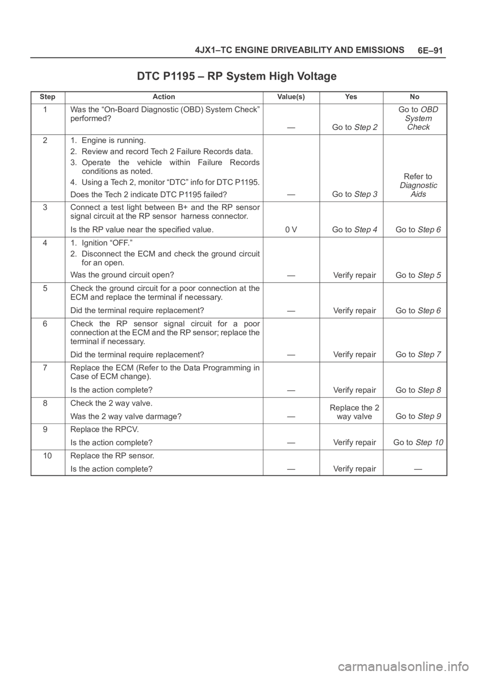
6E–91 4JX1–TC ENGINE DRIVEABILITY AND EMISSIONS
DTC P1195 – RP System High Voltage
StepActionVa l u e ( s )Ye sNo
1Was the “On-Board Diagnostic (OBD) System Check”
performed?
—Go to Step 2
Go to OBD
System
Check
21. Engine is running.
2. Review and record Tech 2 Failure Records data.
3. Operate the vehicle within Failure Records
conditions as noted.
4. Using a Tech 2, monitor “DTC” info for DTC P1195.
Does the Tech 2 indicate DTC P1195 failed?
—Go to Step 3
Refer to
Diagnostic
Aids
3Connect a test light between B+ and the RP sensor
signal circuit at the RP sensor harness connector.
Is the RP value near the specified value.
0 VGo to Step 4Go to Step 6
41. Ignition “OFF.”
2. Disconnect the ECM and check the ground circuit
for an open.
Was the ground circuit open?
—Verify repairGo to Step 5
5Check the ground circuit for a poor connection at the
ECM and replace the terminal if necessary.
Did the terminal require replacement?
—Verify repairGo to Step 6
6Check the RP sensor signal circuit for a poor
connection at the ECM and the RP sensor; replace the
terminal if necessary.
Did the terminal require replacement?
—Verify repairGo to Step 7
7Replace the ECM (Refer to the Data Programming in
Case of ECM change).
Is the action complete?
—Verify repairGo to Step 8
8Check the 2 way valve.
Was the 2 way valve darmage?
—
Replace the 2
way valve
Go to Step 9
9Replace the RPCV.
Is the action complete?
—Verify repairGo to Step 10
10Replace the RP sensor.
Is the action complete?
—Verify repair—
Page 5553 of 6000
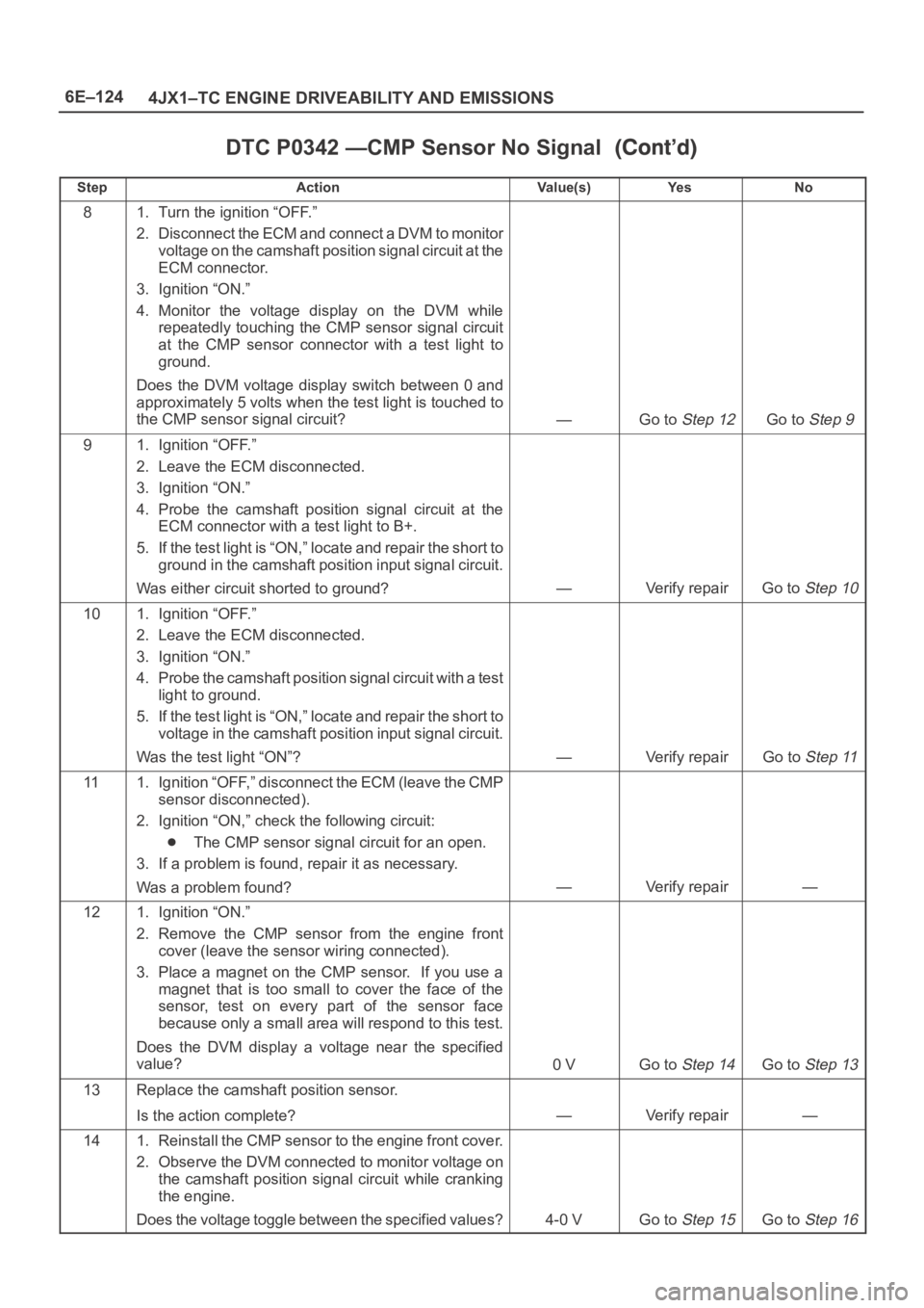
6E–124
4JX1–TC ENGINE DRIVEABILITY AND EMISSIONS
DTC P0342 —CMP Sensor No Signal
StepNo Ye s Va l u e ( s ) Action
81. Turn the ignition “OFF.”
2. Disconnect the ECM and connect a DVM to monitor
voltage on the camshaft position signal circuit at the
ECM connector.
3. Ignition “ON.”
4. Monitor the voltage display on the DVM while
repeatedly touching the CMP sensor signal circuit
at the CMP sensor connector with a test light to
ground.
Does the DVM voltage display switch between 0 and
approximately 5 volts when the test light is touched to
the CMP sensor signal circuit?
—Go to Step 12Go to Step 9
91. Ignition “OFF.”
2. Leave the ECM disconnected.
3. Ignition “ON.”
4. Probe the camshaft position signal circuit at the
ECM connector with a test light to B+.
5. If the test light is “ON,” locate and repair the short to
ground in the camshaft position input signal circuit.
Was either circuit shorted to ground?
—Verify repairGo to Step 10
101. Ignition “OFF.”
2. Leave the ECM disconnected.
3. Ignition “ON.”
4. Probe the camshaft position signal circuit with a test
light to ground.
5. If the test light is “ON,” locate and repair the short to
voltage in the camshaft position input signal circuit.
Was the test light “ON”?
—Verify repairGo to Step 11
111. Ignition “OFF,” disconnect the ECM (leave the CMP
sensor disconnected).
2. Ignition “ON,” check the following circuit:
The CMP sensor signal circuit for an open.
3. If a problem is found, repair it as necessary.
Was a problem found?
—Verify repair—
121. Ignition “ON.”
2. Remove the CMP sensor from the engine front
cover (leave the sensor wiring connected).
3. Place a magnet on the CMP sensor. If you use a
magnet that is too small to cover the face of the
sensor, test on every part of the sensor face
because only a small area will respond to this test.
Does the DVM display a voltage near the specified
value?
0 VGo to Step 14Go to Step 13
13Replace the camshaft position sensor.
Is the action complete?
—Verify repair—
141. Reinstall the CMP sensor to the engine front cover.
2. Observe the DVM connected to monitor voltage on
the camshaft position signal circuit while cranking
the engine.
Does the voltage toggle between the specified values?
4-0 VGo to Step 15Go to Step 16
Page 5582 of 6000
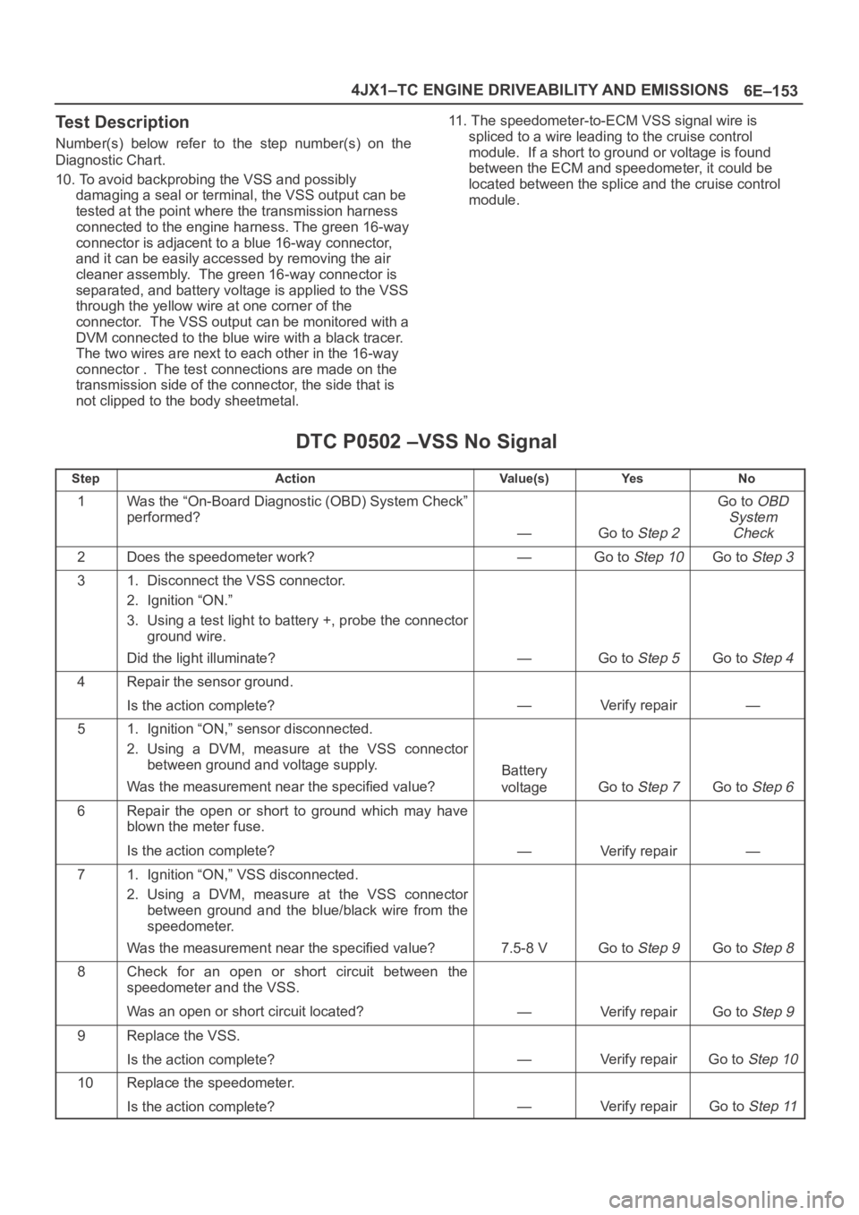
6E–153 4JX1–TC ENGINE DRIVEABILITY AND EMISSIONS
Test Description
Number(s) below refer to the step number(s) on the
Diagnostic Chart.
10. To avoid backprobing the VSS and possibly
damaging a seal or terminal, the VSS output can be
tested at the point where the transmission harness
connected to the engine harness. The green 16-way
connector is adjacent to a blue 16-way connector,
and it can be easily accessed by removing the air
cleaner assembly. The green 16-way connector is
separated, and battery voltage is applied to the VSS
through the yellow wire at one corner of the
connector. The VSS output can be monitored with a
DVM connected to the blue wire with a black tracer.
The two wires are next to each other in the 16-way
connector . The test connections are made on the
transmission side of the connector, the side that is
not clipped to the body sheetmetal.11. The speedometer-to-ECM VSS signal wire is
spliced to a wire leading to the cruise control
module. If a short to ground or voltage is found
between the ECM and speedometer, it could be
located between the splice and the cruise control
module.
DTC P0502 –VSS No Signal
StepActionVa l u e ( s )Ye sNo
1Was the “On-Board Diagnostic (OBD) System Check”
performed?
—Go to Step 2
Go to OBD
System
Check
2Does the speedometer work?—Go to Step 10Go to Step 3
31. Disconnect the VSS connector.
2. Ignition “ON.”
3. Using a test light to battery +, probe the connector
ground wire.
Did the light illuminate?
—Go to Step 5Go to Step 4
4Repair the sensor ground.
Is the action complete?
—Verify repair—
51. Ignition “ON,” sensor disconnected.
2. Using a DVM, measure at the VSS connector
between ground and voltage supply.
Was the measurement near the specified value?
Battery
voltage
Go to Step 7Go to Step 6
6Repair the open or short to ground which may have
blown the meter fuse.
Is the action complete?
—Verify repair—
71. Ignition “ON,” VSS disconnected.
2. Using a DVM, measure at the VSS connector
between ground and the blue/black wire from the
speedometer.
Was the measurement near the specified value?
7.5-8 VGo to Step 9Go to Step 8
8Check for an open or short circuit between the
speedometer and the VSS.
Was an open or short circuit located?
—Verify repairGo to Step 9
9Replace the VSS.
Is the action complete?
—Verify repairGo to Step 10
10Replace the speedometer.
Is the action complete?
—Verify repairGo to Step 11