1998 OPEL FRONTERA diagram
[x] Cancel search: diagramPage 5618 of 6000
6E–189 4JX1–TC ENGINE DRIVEABILITY AND EMISSIONS
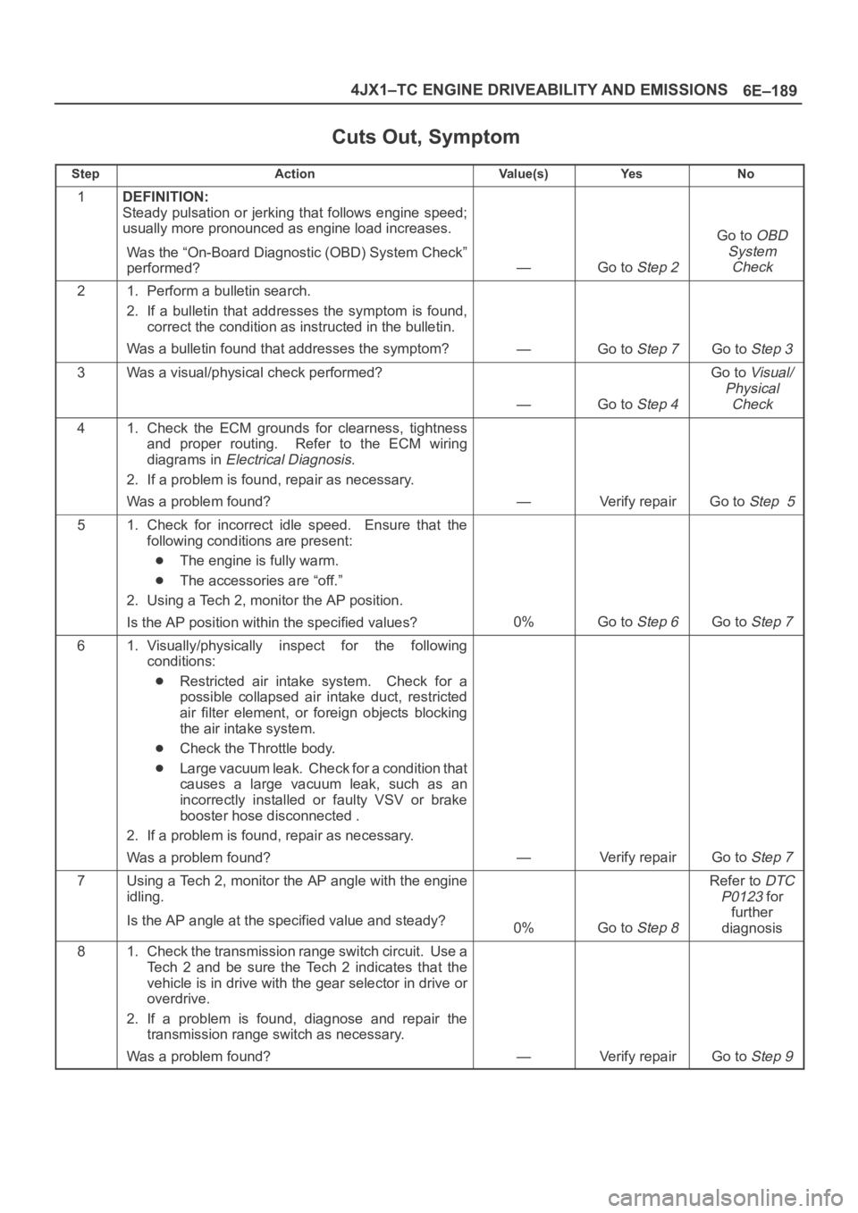
Cuts Out, Symptom
StepActionVa l u e ( s )Ye sNo
1DEFINITION:
Steady pulsation or jerking that follows engine speed;
usually more pronounced as engine load increases.
Was the “On-Board Diagnostic (OBD) System Check”
performed?
—Go to Step 2
Go to OBD
System
Check
21. Perform a bulletin search.
2. If a bulletin that addresses the symptom is found,
correct the condition as instructed in the bulletin.
Was a bulletin found that addresses the symptom?
—Go to Step 7Go to Step 3
3Was a visual/physical check performed?
—Go to Step 4
Go to Visual/
Physical
Check
41. Check the ECM grounds for clearness, tightness
and proper routing. Refer to the ECM wiring
diagrams in
Electrical Diagnosis.
2. If a problem is found, repair as necessary.
Was a problem found?
—Verify repairGo to Step 5
51. Check for incorrect idle speed. Ensure that the
following conditions are present:
The engine is fully warm.
The accessories are “off.”
2. Using a Tech 2, monitor the AP position.
Is the AP position within the specified values?
0%Go to Step 6Go to Step 7
61. Visually/physically inspect for the following
conditions:
Restricted air intake system. Check for a
possible collapsed air intake duct, restricted
air filter element, or foreign objects blocking
the air intake system.
Check the Throttle body.
Large vacuum leak. Check for a condition that
causes a large vacuum leak, such as an
incorrectly installed or faulty VSV or brake
booster hose disconnected .
2. If a problem is found, repair as necessary.
Was a problem found?
—Verify repairGo to Step 7
7Using a Tech 2, monitor the AP angle with the engine
idling.
Is the AP angle at the specified value and steady?
0%Go to Step 8
Refer to DTC
P0123
for
further
diagnosis
81. Check the transmission range switch circuit. Use a
Tech 2 and be sure the Tech 2 indicates that the
vehicle is in drive with the gear selector in drive or
overdrive.
2. If a problem is found, diagnose and repair the
transmission range switch as necessary.
Was a problem found?
—Verify repairGo to Step 9
Page 5646 of 6000
6E–217 4JX1–TC ENGINE DRIVEABILITY AND EMISSIONS
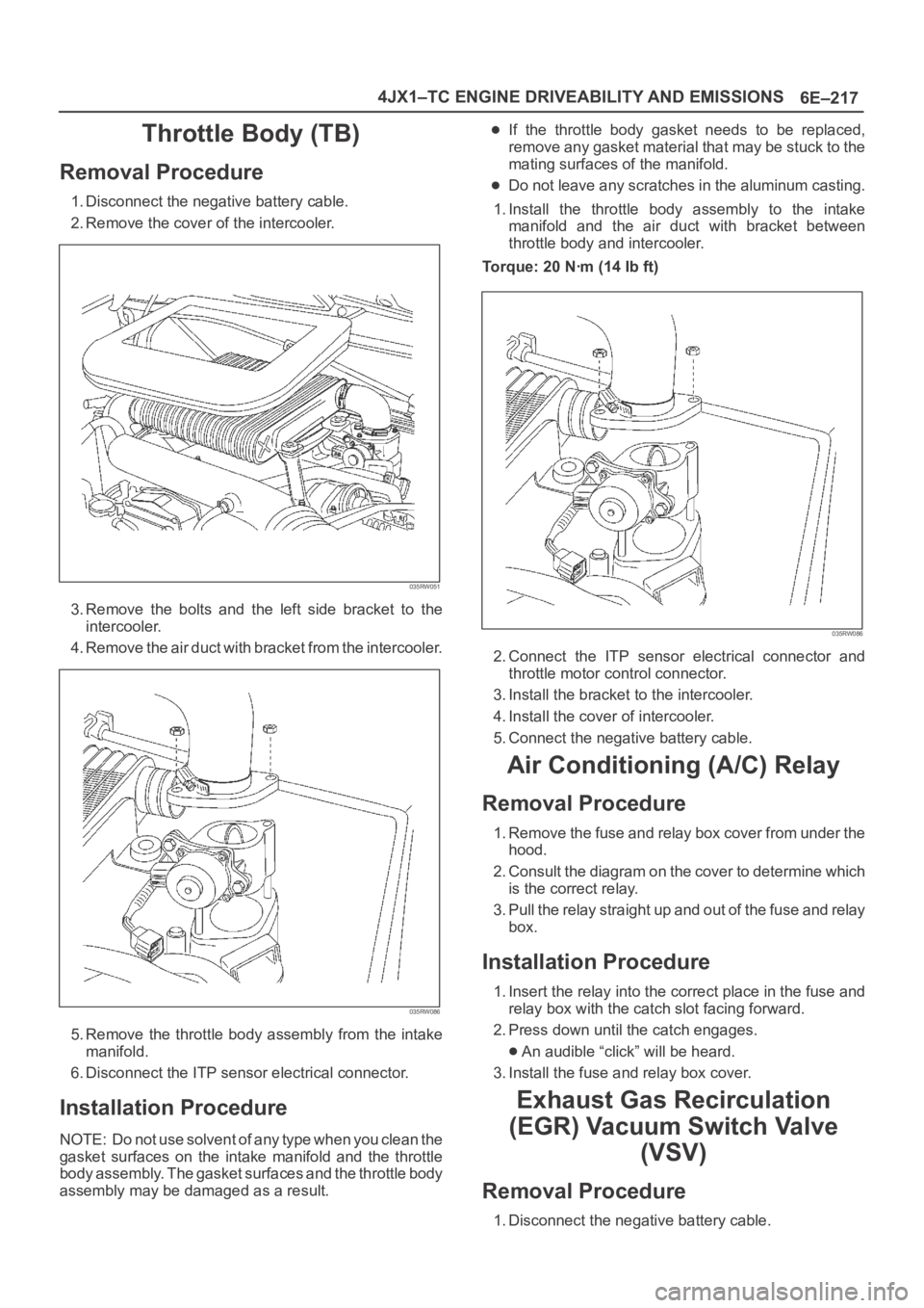
Throttle Body (TB)
Removal Procedure
1. Disconnect the negative battery cable.
2. Remove the cover of the intercooler.
035RW051
3. Remove the bolts and the left side bracket to the
intercooler.
4 . R e m o v e t h e a i r d u c t w i t h b r a c k e t f r o m t h e i n t e r c o o l e r.
035RW086
5. Remove the throttle body assembly from the intake
manifold.
6. Disconnect the ITP sensor electrical connector.
Installation Procedure
NOTE: Do not use solvent of any type when you clean the
gasket surfaces on the intake manifold and the throttle
body assembly. The gasket surfaces and the throttle body
assembly may be damaged as a result.
If the throttle body gasket needs to be replaced,
remove any gasket material that may be stuck to the
mating surfaces of the manifold.
Do not leave any scratches in the aluminum casting.
1. Install the throttle body assembly to the intake
manifold and the air duct with bracket between
throttle body and intercooler.
Torque: 20 Nꞏm (14 Ib ft)
035RW086
2. Connect the ITP sensor electrical connector and
throttle motor control connector.
3. Install the bracket to the intercooler.
4. Install the cover of intercooler.
5. Connect the negative battery cable.
Air Conditioning (A/C) Relay
Removal Procedure
1. Remove the fuse and relay box cover from under the
hood.
2. Consult the diagram on the cover to determine which
is the correct relay.
3. Pull the relay straight up and out of the fuse and relay
box.
Installation Procedure
1. Insert the relay into the correct place in the fuse and
relay box with the catch slot facing forward.
2. Press down until the catch engages.
An audible “click” will be heard.
3. Install the fuse and relay box cover.
Exhaust Gas Recirculation
(EGR) Vacuum Switch Valve
(VSV)
Removal Procedure
1. Disconnect the negative battery cable.
Page 5654 of 6000
6E–225 4JX1–TC ENGINE DRIVEABILITY AND EMISSIONS
General Description
(ECM and Sensors)
57X Reference ECM Input
The engine control module (ECM) uses this signal from
the crankshaft position (CKP) sensor to calculate engine
RPM and crankshaft position at all engine speeds. The
ECM also uses the pulses on this circuit to initiate injector
pulses. If the ECM receives no pulses on this circuit, DTC
P0337 will set. The engine will not start and run without
using the 57X reference signal.
A/C Request Signal
This signal tells the ECM when the A/C mode is selected
at the A/C control head.
Refer to
A/C Clutch Circuit Diagnosis for A/C wiring
diagrams and diagnosis for the A/C electrical system.
Crankshaft Position (CKP) Sensor
The crankshaft position (CKP) sensor provides a signal
used by the engine control module (ECM) to calculate the
ignition sequence. The CKP sensor initiates the 57X
reference pulses which the ECM uses to calculate RPM
and crankshaft position.
Refer to
Electronic Ignition System for additional
information.
Camshaft Position (CMP) Sensor and
Signal
The camshaft position (CMP) sensor sends a CMP signal
to the ECM. The ECM uses this signal as a “cylinder
distinction” to trigger the injectors in the power order. If the
ECM detects an incorrect CMP signal while the engine is
running, DTC P0341 will set, and the ECM triggers the
injectors in the power order.
Refer to
DTC P0341.
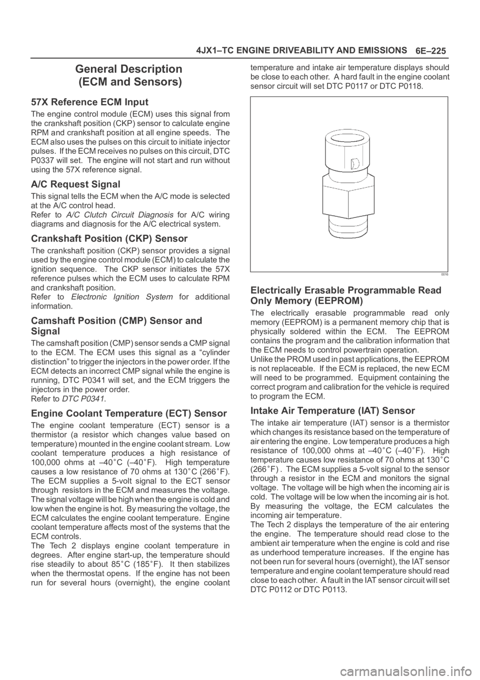
Engine Coolant Temperature (ECT) Sensor
The engine coolant temperature (ECT) sensor is a
thermistor (a resistor which changes value based on
temperature) mounted in the engine coolant stream. Low
coolant temperature produces a high resistance of
100,000 ohms at –40
C (–40F). High temperature
causes a low resistance of 70 ohms at 130
C (266F).
The ECM supplies a 5-volt signal to the ECT sensor
through resistors in the ECM and measures the voltage.
The signal voltage will be high when the engine is cold and
low when the engine is hot. By measuring the voltage, the
ECM calculates the engine coolant temperature. Engine
coolant temperature affects most of the systems that the
ECM controls.
The Tech 2 displays engine coolant temperature in
degrees. After engine start-up, the temperature should
rise steadily to about 85
C (185F). It then stabilizes
when the thermostat opens. If the engine has not been
run for several hours (overnight), the engine coolanttemperature and intake air temperature displays should
be close to each other. A hard fault in the engine coolant
sensor circuit will set DTC P0117 or DTC P0118.
0016
Electrically Erasable Programmable Read
Only Memory (EEPROM)
The electrically erasable programmable read only
memory (EEPROM) is a permanent memory chip that is
physically soldered within the ECM. The EEPROM
contains the program and the calibration information that
the ECM needs to control powertrain operation.
Unlike the PROM used in past applications, the EEPROM
is not replaceable. If the ECM is replaced, the new ECM
will need to be programmed. Equipment containing the
correct program and calibration for the vehicle is required
to program the ECM.
Intake Air Temperature (IAT) Sensor
The intake air temperature (IAT) sensor is a thermistor
which changes its resistance based on the temperature of
air entering the engine. Low temperature produces a high
resistance of 100,000 ohms at –40
C (–40F). High
temperature causes low resistance of 70 ohms at 130
C
(266
F) . The ECM supplies a 5-volt signal to the sensor
through a resistor in the ECM and monitors the signal
voltage. The voltage will be high when the incoming air is
cold. The voltage will be low when the incoming air is hot.
By measuring the voltage, the ECM calculates the
incoming air temperature.
The Tech 2 displays the temperature of the air entering
the engine. The temperature should read close to the
ambient air temperature when the engine is cold and rise
as underhood temperature increases. If the engine has
not been run for several hours (overnight), the IAT sensor
temperature and engine coolant temperature should read
close to each other. A fault in the IAT sensor circuit will set
DTC P0112 or DTC P0113.
Page 5657 of 6000
6E–228
4JX1–TC ENGINE DRIVEABILITY AND EMISSIONS
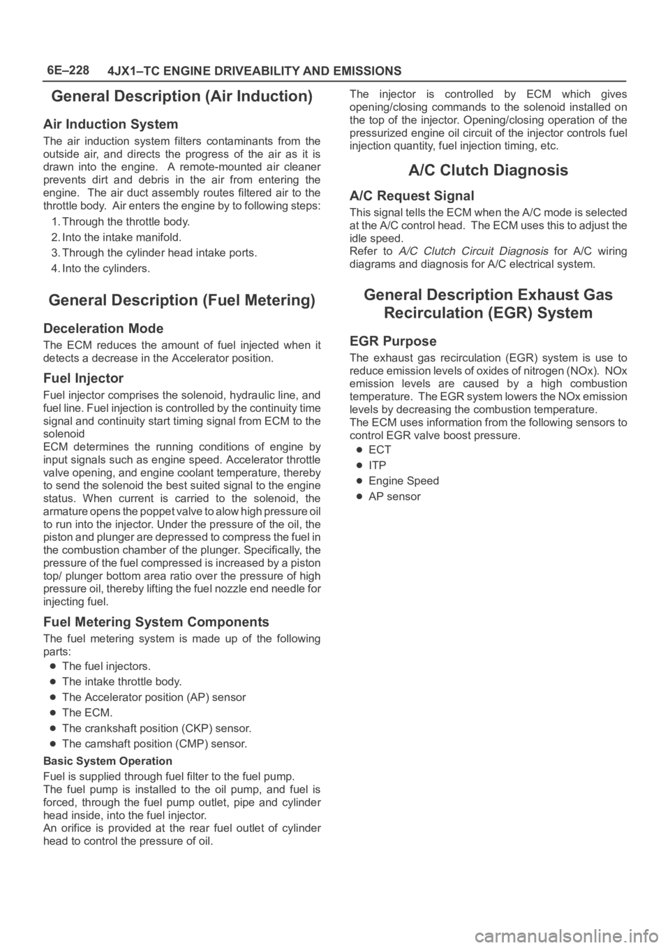
General Description (Air Induction)
Air Induction System
The air induction system filters contaminants from the
outside air, and directs the progress of the air as it is
drawn into the engine. A remote-mounted air cleaner
prevents dirt and debris in the air from entering the
engine. The air duct assembly routes filtered air to the
throttle body. Air enters the engine by to following steps:
1. Through the throttle body.
2. Into the intake manifold.
3. Through the cylinder head intake ports.
4. Into the cylinders.
General Description (Fuel Metering)
Deceleration Mode
The ECM reduces the amount of fuel injected when it
detects a decrease in the Accelerator position.
Fuel Injector
Fuel injector comprises the solenoid, hydraulic line, and
fuel line. Fuel injection is controlled by the continuity time
signal and continuity start timing signal from ECM to the
solenoid
ECM determines the running conditions of engine by
input signals such as engine speed. Accelerator throttle
valve opening, and engine coolant temperature, thereby
to send the solenoid the best suited signal to the engine
status. When current is carried to the solenoid, the
armature opens the poppet valve to alow high pressure oil
to run into the injector. Under the pressure of the oil, the
piston and plunger are depressed to compress the fuel in
the combustion chamber of the plunger. Specifically, the
pressure of the fuel compressed is increased by a piston
top/ plunger bottom area ratio over the pressure of high
pressure oil, thereby lifting the fuel nozzle end needle for
injecting fuel.
Fuel Metering System Components
The fuel metering system is made up of the following
parts:
The fuel injectors.
The intake throttle body.
The Accelerator position (AP) sensor
The ECM.
The crankshaft position (CKP) sensor.
The camshaft position (CMP) sensor.
Basic System Operation
Fuel is supplied through fuel filter to the fuel pump.
The fuel pump is installed to the oil pump, and fuel is
forced, through the fuel pump outlet, pipe and cylinder
head inside, into the fuel injector.
An orifice is provided at the rear fuel outlet of cylinder
head to control the pressure of oil.The injector is controlled by ECM which gives
opening/closing commands to the solenoid installed on
the top of the injector. Opening/closing operation of the
pressurized engine oil circuit of the injector controls fuel
injection quantity, fuel injection timing, etc.
A/C Clutch Diagnosis
A/C Request Signal
This signal tells the ECM when the A/C mode is selected
at the A/C control head. The ECM uses this to adjust the
idle speed.
Refer to
A/C Clutch Circuit Diagnosis for A/C wiring
diagrams and diagnosis for A/C electrical system.
General Description Exhaust Gas
Recirculation (EGR) System
EGR Purpose
The exhaust gas recirculation (EGR) system is use to
reduce emission levels of oxides of nitrogen (NOx). NOx
emission levels are caused by a high combustion
temperature. The EGR system lowers the NOx emission
levels by decreasing the combustion temperature.
The ECM uses information from the following sensors to
control EGR valve boost pressure.
ECT
ITP
Engine Speed
AP sensor
Page 5782 of 6000

AUTOMATIC TRANSMISSION (AW30-40LE) 7A–1
SECTION 7A
CONTENTS
AUTOMATIC TRANSMISSION (AW30-40LE)
GENERAL DESCRIPTION . . . . . . . . . . . . . . . . . . . . . . . . . . . . . . . . . . . . . . . . . . . . . . . . . . . . . . . . . . . . . 7A–3
CONSTRUCTION . . . . . . . . . . . . . . . . . . . . . . . . . . . . . . . . . . . . . . . . . . . . . . . . . . . . . . . . . . . . . . . . . . . 7A–3
ELECTRONIC CONTROL COMPONENTS . . . . . . . . . . . . . . . . . . . . . . . . . . . . . . . . . . . . . . . . . . . . . . . 7A–4
TRANSMISSION CONTROL MODULE (TCM) . . . . . . . . . . . . . . . . . . . . . . . . . . . . . . . . . . . . . . . . . . . . 7A–5
CONTROL SYSTEM DIAGRAM. . . . . . . . . . . . . . . . . . . . . . . . . . . . . . . . . . . . . . . . . . . . . . . . . . . . . . . . 7A–6
CONTROL AND FUNCTIONS . . . . . . . . . . . . . . . . . . . . . . . . . . . . . . . . . . . . . . . . . . . . . . . . . . . . . . . . . 7A–7
MAJOR INPUT/OUTPUT COMPONENTS . . . . . . . . . . . . . . . . . . . . . . . . . . . . . . . . . . . . . . . . . . . . . . . . 7A–9
LOCATION OF CLUTCH, BRAKE ONE-WAY CLUTCH AND SOLENOID . . . . . . . . . . . . . . . . . . . . . . . 7A–10
OPERATION OF CLUTCH, BRAKE AND ONE-WAY CLUTCH . . . . . . . . . . . . . . . . . . . . . . . . . . . . . . . 7A–11
SPEED CHANGE AND LOCK-UP PATTERN . . . . . . . . . . . . . . . . . . . . . . . . . . . . . . . . . . . . . . . . . . . . . . 7A–11
OVERDRIVE AND LOCK-UP OPERATING CONDITIONS . . . . . . . . . . . . . . . . . . . . . . . . . . . . . . . . . . . 7A–12
DIAGNOSIS . . . . . . . . . . . . . . . . . . . . . . . . . . . . . . . . . . . . . . . . . . . . . . . . . . . . . . . . . . . . . . . . . . . . . . . . . 7A–13
BASIC TROUBLESHOOTING
. . . . . . . . . . . . . . . . . . . . . . . . . . . . . . . . . . . . . . . . . . . . . . . . 7A–13
SELF-DIAGNOSIS . . . . . . . . . . . . . . . . . . . . . . . . . . . . . . . . . . . . . . . . . . . . . . . . . . . . . . . . . . . . . . . . . . 7A–14
DIAGNOSIS WITH TECH2 . . . . . . . . . . . . . . . . . . . . . . . . . . . . . . . . . . . . . . . . . . . . . . . . . . . . . . . . . . . . 7A–17
TECH2 CONNECTION . . . . . . . . . . . . . . . . . . . . . . . . . . . . . . . . . . . . . . . . . . . . . . . . . . . . . . . . . . . . . . . 7A–18
TECH2 OPERATING FLOW CHART (START UP) . . . . . . . . . . . . . . . . . . . . . . . . . . . . . . . . . . . . . . . . . 7A–19
TRANSMISSION DATA . . . . . . . . . . . . . . . . . . . . . . . . . . . . . . . . . . . . . . . . . . . . . . . . . . . . . . . . . . . . . . 7A–21
TCC DATA . . . . . . . . . . . . . . . . . . . . . . . . . . . . . . . . . . . . . . . . . . . . . . . . . . . . . . . . . . . . . . . . . . . . . . . . 7A–22
INTERMITTENT CONDITIONS . . . . . . . . . . . . . . . . . . . . . . . . . . . . . . . . . . . . . . . . . . . . . . . . . . . . . . . . 7A–23
IDENTIFICATION OF TRANSMISSION CONTROL MODULE (TCM) . . . . . . . . . . . . . . . . . . . . . . . . . . . 7A–24
DIAGNOSTIC TROUBLE CODES (DTC) CHECK . . . . . . . . . . . . . . . . . . . . . . . . . . . . . . . . . . . . . . . . . . 7A–25
WIRING DIAGRAM . . . . . . . . . . . . . . . . . . . . . . . . . . . . . . . . . . . . . . . . . . . . . . . . . . . . . . . . . . . . . . . . . 7A–52
CONNECTOR LIST . . . . . . . . . . . . . . . . . . . . . . . . . . . . . . . . . . . . . . . . . . . . . . . . . . . . . . . . . . . . . . . . . 7A–54
TROUBLESHOOTING CHART . . . . . . . . . . . . . . . . . . . . . . . . . . . . . . . . . . . . . . . . . . . . . . . . . . . . . . . . 7A–56
MANUAL SHIFTING TEST . . . . . . . . . . . . . . . . . . . . . . . . . . . . . . . . . . . . . . . . . . . . . . . . . . . . . . . . . . . . 7A–62
STALL TEST . . . . . . . . . . . . . . . . . . . . . . . . . . . . . . . . . . . . . . . . . . . . . . . . . . . . . . . . . . . . . . . . . . . . . . . 7A–63
TIME LAG TEST . . . . . . . . . . . . . . . . . . . . . . . . . . . . . . . . . . . . . . . . . . . . . . . . . . . . . . . . . . . . . . . . . . . . 7A–64
HYDRAULIC TEST . . . . . . . . . . . . . . . . . . . . . . . . . . . . . . . . . . . . . . . . . . . . . . . . . . . . . . . . . . . . . . . . . . 7A–65
ROAD TEST . . . . . . . . . . . . . . . . . . . . . . . . . . . . . . . . . . . . . . . . . . . . . . . . . . . . . . . . . . . . . . . . . . . . . . . 7A–66
SHIFT POINT CHART AND LOCK-UP POINT CHART . . . . . . . . . . . . . . . . . . . . . . . . . . . . . . . . . . . . . . 7A–69
TCM VOLTAGE CHECK . . . . . . . . . . . . . . . . . . . . . . . . . . . . . . . . . . . . . . . . . . . . . . . . . . . . . . . . . . . . . . 7A–71
TCM STANDARD VOLTAGE . . . . . . . . . . . . . . . . . . . . . . . . . . . . . . . . . . . . . . . . . . . . . . . . . . . . . . . . . . 7A–72
ON-VEHICLE SERVICE . . . . . . . . . . . . . . . . . . . . . . . . . . . . . . . . . . . . . . . . . . . . . . . . . . . . . . . . . . . . . . . 7A–75
TRANSIMISSION FLUID LEVEL AND CONDITION . . . . . . . . . . . . . . . . . . . . . . . . . . . . . . . . . . . . . . . . 7A–75
ATF REPLACEMENT . . . . . . . . . . . . . . . . . . . . . . . . . . . . . . . . . . . . . . . . . . . . . . . . . . . . . . . . . . . . . . . . 7A–75
NEUTRAL START SWITCH INSPECTION. . . . . . . . . . . . . . . . . . . . . . . . . . . . . . . . . . . . . . . . . . . . . . . . 7A–76
BRAKE SIGNAL INSPECTION . . . . . . . . . . . . . . . . . . . . . . . . . . . . . . . . . . . . . . . . . . . . . . . . . . . . . . . . 7A–77
VEHICLE SPEED SENSOR INSPECTION . . . . . . . . . . . . . . . . . . . . . . . . . . . . . . . . . . . . . . . . . . . . . . . 7A–77
INPUT AND OUTPUT REVOLUTION SENSOR INSPECTION . . . . . . . . . . . . . . . . . . . . . . . . . . . . . . . . 7A–77
PATTERN SELECT SWITCH INSPECTION . . . . . . . . . . . . . . . . . . . . . . . . . . . . . . . . . . . . . . . . . . . . . . . 7A–78
OVERDRIVE OFF SWITCH INSPECTION . . . . . . . . . . . . . . . . . . . . . . . . . . . . . . . . . . . . . . . . . . . . . . . 7A–78
SOLENOID INSPECTION . . . . . . . . . . . . . . . . . . . . . . . . . . . . . . . . . . . . . . . . . . . . . . . . . . . . . . . . . . . . 7A–78
THROTTLE POSITION SENSOR INSPECTION . . . . . . . . . . . . . . . . . . . . . . . . . . . . . . . . . . . . . . . . . . . 7A–79
ATF TEMPERATURE SENSOR INSPECTION. . . . . . . . . . . . . . . . . . . . . . . . . . . . . . . . . . . . . . . . . . . . . 7A–79
SELECTOR LEVER . . . . . . . . . . . . . . . . . . . . . . . . . . . . . . . . . . . . . . . . . . . . . . . . . . . . . . . . . . . . . . . . . 7A–80
TRANSMISSION CONTROL MODULE (TCM) . . . . . . . . . . . . . . . . . . . . . . . . . . . . . . . . . . . . . . . . . . . . 7A–81
SHIFT SOLENOID AND LOCK-UP SOLENOID. . . . . . . . . . . . . . . . . . . . . . . . . . . . . . . . . . . . . . . . . . . . 7A–83
Page 5787 of 6000
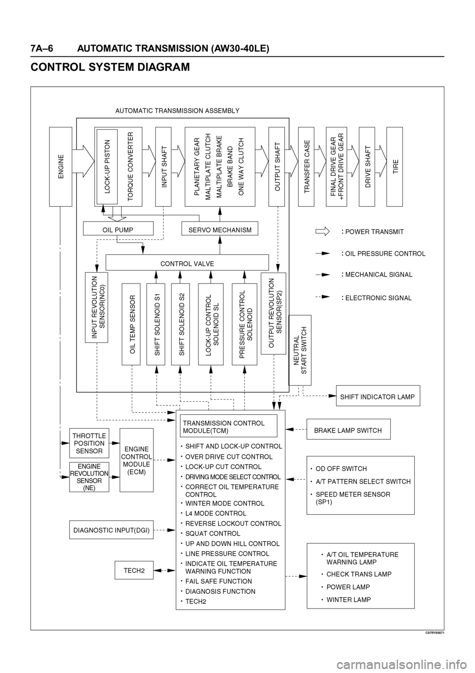
7A–6 AUTOMATIC TRANSMISSION (AW30-40LE)
CONTROL SYSTEM DIAGRAM
C07RY00071
Page 5833 of 6000
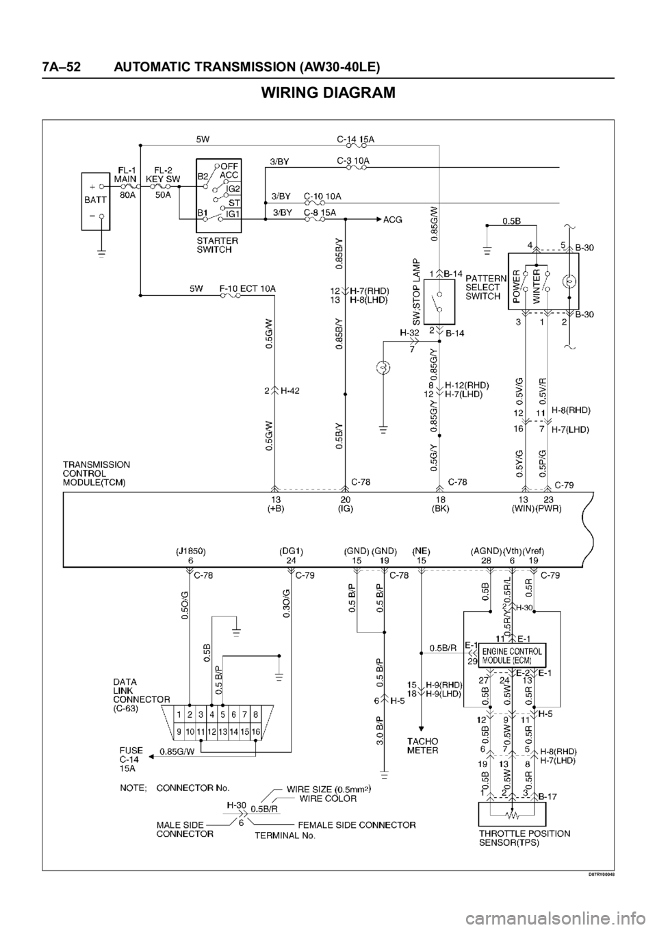
7A–52 AUTOMATIC TRANSMISSION (AW30-40LE)
WIRING DIAGRAM
D07RY00048
Page 5834 of 6000
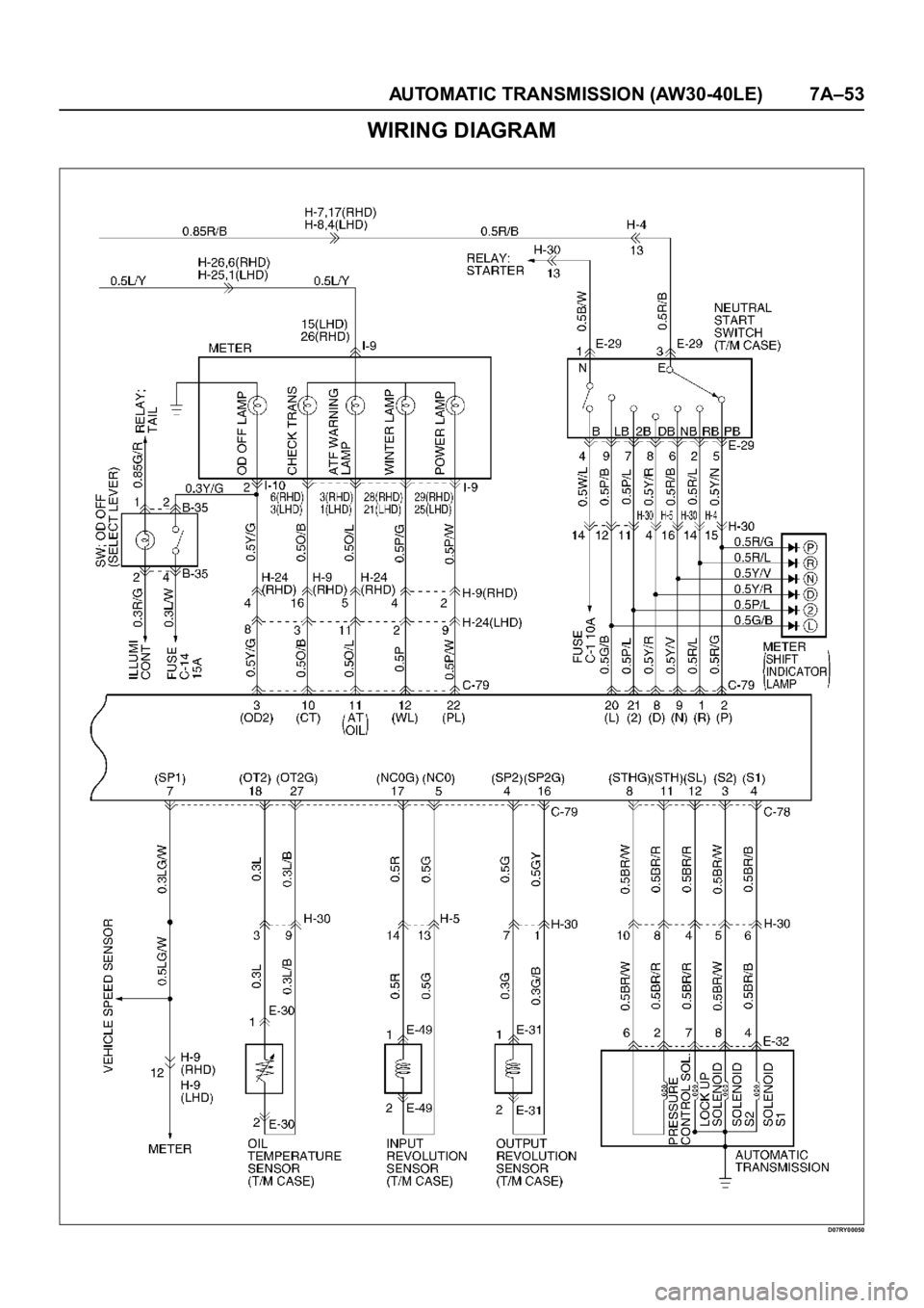
AUTOMATIC TRANSMISSION (AW30-40LE) 7A–53
WIRING DIAGRAM
D07RY00050