Page 5847 of 6000

7A–66 AUTOMATIC TRANSMISSION (AW30-40LE)
255RT004
F07RY00005
F07RY00006
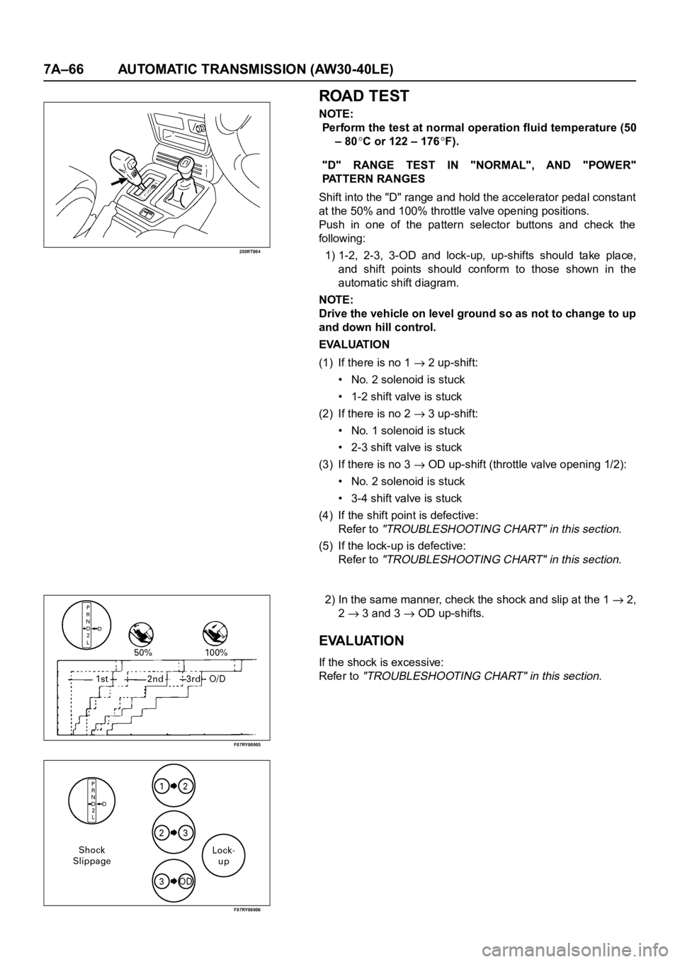
ROAD TEST
NOTE:
Perform the test at normal operation fluid temperature (50
– 80
C or 122 – 176F).
"D" RANGE TEST IN "NORMAL", AND "POWER"
PATTERN RANGES
Shift into the "D" range and hold the accelerator pedal constant
at the 50% and 100% throttle valve opening positions.
Push in one of the pattern selector buttons and check the
fol lowing:
1) 1-2, 2-3, 3-OD and lock-up, up-shifts should take place,
and shift points should conform to those shown in the
automatic shift diagram.
NOTE:
Drive the vehicle on level ground so as not to change to up
and down hill control.
EVALUATION
(1) If there is no 1
2 up-shift:
• No. 2 solenoid is stuck
• 1-2 shift valve is stuck
(2) If there is no 2
3 up-shift:
• No. 1 solenoid is stuck
• 2-3 shift valve is stuck
(3) If there is no 3
OD up-shift (throttle valve opening 1/2):
• No. 2 solenoid is stuck
• 3-4 shift valve is stuck
(4) If the shift point is defective:
Refer to
"TROUBLESHOOTING CHART" in this section.
(5) If the lock-up is defective:
Refer to
"TROUBLESHOOTING CHART" in this section.
2) In the same manner, check the shock and slip at the 1 2,
2
3 and 3 OD up-shifts.
EVALUATION
If the shock is excessive:
Refer to
"TROUBLESHOOTING CHART" in this section.
Page 5848 of 6000

AUTOMATIC TRANSMISSION (AW30-40LE) 7A–67
F07RY00007
F07RY00008
F07RY00009
F07RY00010
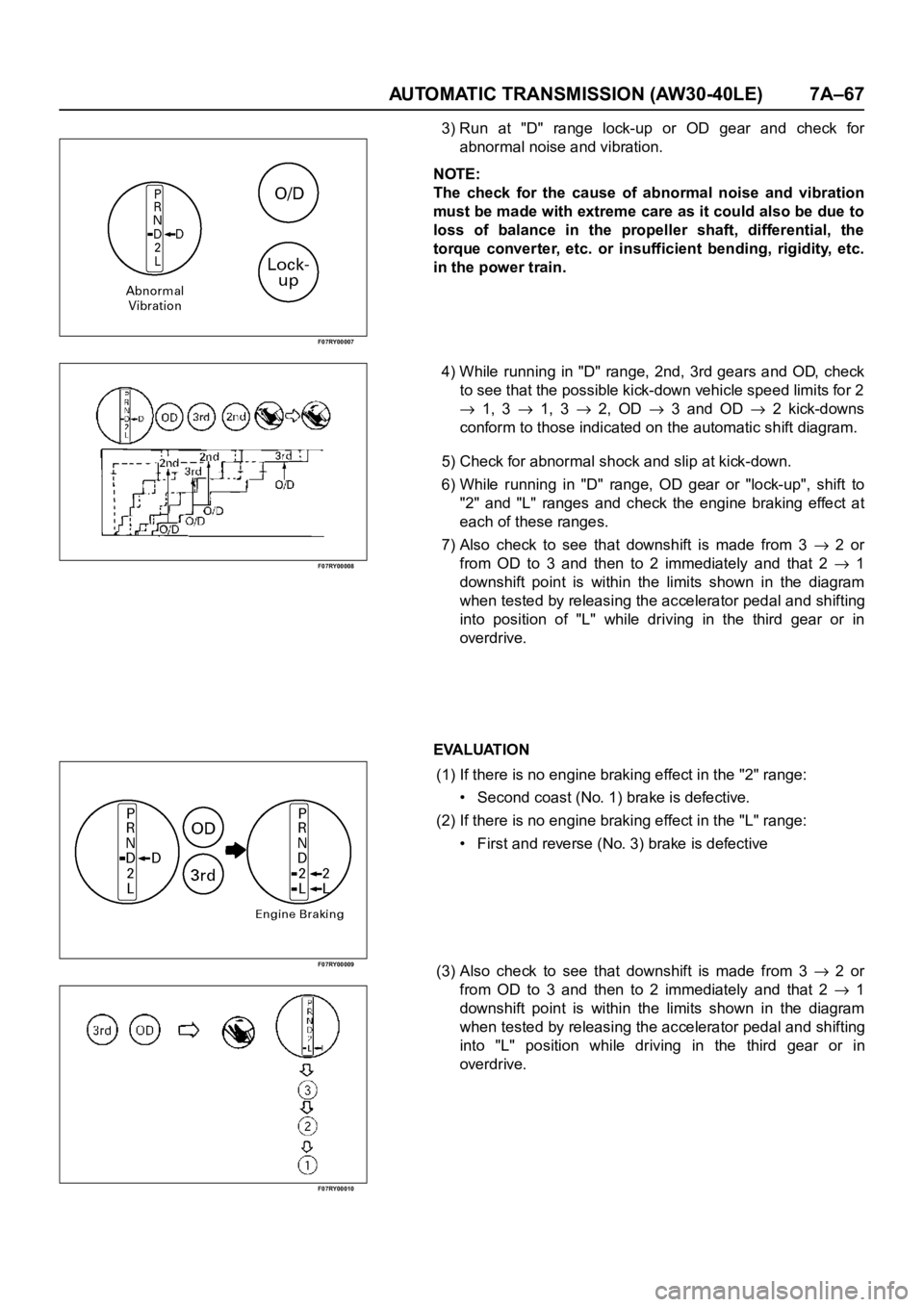
3) Run at "D" range lock-up or OD gear and check for
abnormal noise and vibration.
NOTE:
The check for the cause of abnormal noise and vibration
must be made with extreme care as it could also be due to
loss of balance in the propeller shaft, differential, the
torque converter, etc. or insufficient bending, rigidity, etc.
in the power train.
4) While running in "D" range, 2nd, 3rd gears and OD, check
to see that the possible kick-down vehicle speed limits for 2
1, 3 1, 3 2, OD 3 and OD 2 kick-downs
conform to those indicated on the automatic shift diagram.
5) Check for abnormal shock and slip at kick-down.
6) While running in "D" range, OD gear or "lock-up", shift to
"2" and "L" ranges and check the engine braking effect at
each of these ranges.
7) Also check to see that downshift is made from 3
2 or
from OD to 3 and then to 2 immediately and that 2
1
downshift point is within the limits shown in the diagram
when tested by releasing the accelerator pedal and shifting
into position of "L" while driving in the third gear or in
overdrive.
EVALUATION
(1) If there is no engine braking effect in the "2" range:
• Second coast (No. 1) brake is defective.
(2) If there is no engine braking effect in the "L" range:
• First and reverse (No. 3) brake is defective
(3) Also check to see that downshift is made from 3
2 or
from OD to 3 and then to 2 immediately and that 2
1
downshift point is within the limits shown in the diagram
when tested by releasing the accelerator pedal and shifting
into "L" position while driving in the third gear or in
overdrive.
Page 5849 of 6000

7A–68 AUTOMATIC TRANSMISSION (AW30-40LE)
F07RY00011
F07RY00012
F07RY00020
F07RY00014
F07RY00015
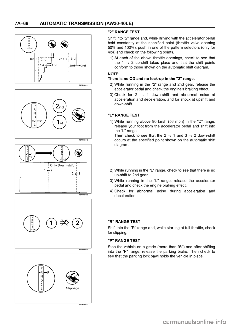
"2" RANGE TEST
Shift into "2" range and, while driving with the accelerator pedal
held constantly at the specified point (throttle valve opening
50% and 100%), push in one of the pattern selectors (only for
4x4) and check on the following points.
1) At each of the above throttle openings, check to see that
the 1
2 up-shift takes place and that the shift points
conform to those shown on the automatic shift diagram.
NOTE:
There is no OD and no lock-up in the "2" range.
2) While running in the "2" range and 2nd gear, release the
accelerator pedal and check the engine's braking effect.
3) Check for 2
1 down-shift and abnormal noise at
acceleration and deceleration, and for shock at upshift and
down-shift.
"L" RANGE TEST
1) While running above 90 km/h (56 mph) in the "D" range,
release your foot from the accelerator pedal and shift into
the "L" range.
Then check to see that the 2
1 and 3 2 down-shift
occurs at the specified point shown on the automatic shift
diagram.
2) While running in the "L" range, check to see that there is no
up-shift to 2nd gear.
3) While running in the "L" range, release the accelerator
pedal and check the engine braking effect.
4) Check for abnormal noise during acceleration and
deceleration.
"R" RANGE TEST
Shift into the "R" range and, while starting at full throttle, check
for slipping.
"P" RANGE TEST
Stop the vehicle on a grade (more than 9%) and after shifting
into the "P" range, release the parking brake. Then check to
see that the parking lock pawl holds the vehicle in place.
Page 5994 of 6000

TRANSMISSION CONTROL SYSTEM (4L30–E)7A1–1
TRANSMISSION
TRANSMISSION CONTROL SYSTEM (4L30–E)
CONTENTS
Service Precaution 7A1–2. . . . . . . . . . . . . . . . . . . . . .
General Description 7A1–2. . . . . . . . . . . . . . . . . . . . .
Electronic Control Diagram 7A1–3. . . . . . . . . . . . .
Powertrain Control Module (PCM) 7A1–4. . . . . . .
Control System Diagram 7A1–5. . . . . . . . . . . . . . .
Shift Control 7A1–6. . . . . . . . . . . . . . . . . . . . . . . . . .
Band Apply Control 7A1–6. . . . . . . . . . . . . . . . . . . .
Torque Converter Clutch Control 7A1–6. . . . . . . . .
Line Pressure Control 7A1–6. . . . . . . . . . . . . . . . . .
On–Board Diagnostic System 7A1–6. . . . . . . . . . .
Fail Safe Mechanism 7A1–6. . . . . . . . . . . . . . . . . . .
Torque Management Control 7A1–6. . . . . . . . . . . .
ATF Warning Control 7A1–6. . . . . . . . . . . . . . . . . . .
ABS Control (If equipped) 7A1–6. . . . . . . . . . . . . .
Shift Mode Control 7A1–7. . . . . . . . . . . . . . . . . . . . .
Gear Shift Control 7A1–8. . . . . . . . . . . . . . . . . . . . .
Winter Drive Mode 7A1–9. . . . . . . . . . . . . . . . . . . . .
Backup Mode 7A1–9. . . . . . . . . . . . . . . . . . . . . . . . .
Functions of Input / Output Components 7A1–10. .
Diagnosis 7A1–11. . . . . . . . . . . . . . . . . . . . . . . . . . . . . .
Electronic Diagnosis 7A1–11. . . . . . . . . . . . . . . . . . .
Check Trans Indicator 7A1–11. . . . . . . . . . . . . . . . . .
Diagnostic Check 7A1–11. . . . . . . . . . . . . . . . . . . . . .
“Check Trans” Check 7A1–12. . . . . . . . . . . . . . . . . .
Tech2 OBD II Connection 7A1–13. . . . . . . . . . . . . . .
F0: Transmission Data 7A1–18. . . . . . . . . . . . . . . . .
F1: PC Solenoid Data 7A1–19. . . . . . . . . . . . . . . . . .
OBD II Diagnostic Management System 7A1–20. .
16 – Terminal Data Link Connector (DLC) 7A1–21.
Malfunction Indicator Lamp (MIL) 7A1–22. . . . . . . .
Types Of Diagnostic Trouble Codes (DTCs) 7A1–22
Clear DTC 7A1–22. . . . . . . . . . . . . . . . . . . . . . . . . . . .
DTC Check 7A1–23. . . . . . . . . . . . . . . . . . . . . . . . . . .
PCM Precaution 7A1–23. . . . . . . . . . . . . . . . . . . . . . .
Information On PCM 7A1–23. . . . . . . . . . . . . . . . . . .
Intermittent Conditions 7A1–23. . . . . . . . . . . . . . . . . Transmission And PCM Identification 7A1–24. . . . .
Isuzu Trooper 7A1–25. . . . . . . . . . . . . . . . . . . . . . . . .
Diagnostic Trouble Code (DTC)
Identification 7A1–26. . . . . . . . . . . . . . . . . . . . . . . . .
DTC P0218 Transmission Fluid Over
Temperature 7A1–27. . . . . . . . . . . . . . . . . . . . . . . . . . .
DTC P0560 System Voltage Malfunction 7A1–29. . .
DTC P0705 Transmission Range Switch
(Mode Switch) Illegal Position 7A1–32. . . . . . . . . . . .
DTC P0706 Transmission Range Switch
(Mode Switch) Performance 7A1–35. . . . . . . . . . . . . .
DTC P0712 Transmission Fluid Temperature
(TFT) Sensor Circuit Low Input 7A1–38. . . . . . . . . . .
DTC P0713 Transmission Fluid Temperature
(TFT) Sensor Circuit High Input 7A1–41. . . . . . . . . . .
DTC P0719 TCC Brake Switch Circuit High
(Stuck On) 7A1–44. . . . . . . . . . . . . . . . . . . . . . . . . . . . .
DTC P0722 Transmission Output Speed
Sensor (OSS) Low Input 7A1–47
. . . . . . . . . . . . . . . . .
DTC P0723 Transmission Output Speed
Sensor (OSS) Intermittent 7A1–50. . . . . . . . . . . . . . .
DTC P0730 Transmission Incorrect Gear
Ratio 7A1–53. . . . . . . . . . . . . . . . . . . . . . . . . . . . . . . . . .
DTC P0748 Pressure Control Solenoid
(PCS) (Force Motor) Circuit Electrical 7A1–56. . . . .
DTC P0753 Shift Solenoid A Electrical 7A1–58. . . . .
DTC P0758 Shift Solenoid B Electrical 7A1–61. . . . .
DTC P1790 ROM Transmission Side Bad
Check Sum 7A1–65. . . . . . . . . . . . . . . . . . . . . . . . . . . .
DTC P1792 EEPROM Transmission Side
Bad Check Sum 7A1–66. . . . . . . . . . . . . . . . . . . . . . . .
DTC P1835 Kickdown Switch Always On 7A1–67. . .
DTC P1850 Brake Band Apply Solenoid
Malfunction 7A1–69. . . . . . . . . . . . . . . . . . . . . . . . . . . .
DTC P1860 TCC Solenoid Electrical 7A1–73. . . . . . .
Transmission Fluid Temperature (TFT)
Sensor Specifications 7A1–76. . . . . . . . . . . . . . . . . . .
Page 5996 of 6000
TRANSMISSION CONTROL SYSTEM (4L30–E)7A1–3
Electronic Control Diagram
C07RW052
Page 5998 of 6000
TRANSMISSION CONTROL SYSTEM (4L30–E)7A1–5
Control System Diagram
C07RY00031