1998 OPEL FRONTERA oil pressure
[x] Cancel search: oil pressurePage 1983 of 6000
6E–90
4JX1–TC ENGINE DRIVEABILITY AND EMISSIONS
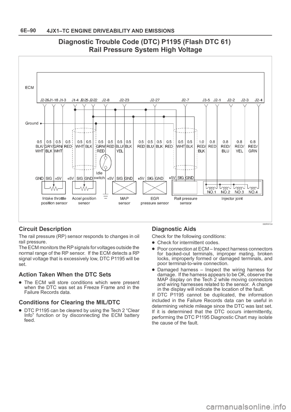
Diagnostic Trouble Code (DTC) P1195 (Flash DTC 61)
Rail Pressure System High Voltage
060RW134
Circuit Description
The rail pressure (RP) sensor responds to changes in oil
rail pressure.
The ECM monitors the RP signals for voltages outside the
normal range of the RP sensor. If the ECM detects a RP
signal voltage that is excessively low, DTC P1195 will be
set.
Action Taken When the DTC Sets
The ECM will store conditions which were present
when the DTC was set as Freeze Frame and in the
Failure Records data.
Conditions for Clearing the MIL/DTC
DTC P1195 can be cleared by using the Tech 2 “Clear
Info” function or by disconnecting the ECM battery
feed.
Diagnostic Aids
Check for the following conditions:
Check for intermittent codes.
Poor connection at ECM – Inspect harness connectors
for backed-out terminals, improper mating, broken
locks, improperly formed or damaged terminals, and
poor terminal-to-wire connection.
Damaged harness – Inspect the wiring harness for
damage. If the harness appears to be OK, observe the
MAP display on the Tech 2 while moving connectors
and wiring harnesses related to the sensor. A change
in the display will indicate the location of the fault.
If DTC P1195 cannot be duplicated, the information
included in the Failure Records data can be useful in
determining vehicle mileage since the DTC was last set.
If it is determined that the DTC occurs intermittently,
performing the DTC P1195 Diagnostic Chart may isolate
the cause of the fault.
Page 1985 of 6000
6E–92
4JX1–TC ENGINE DRIVEABILITY AND EMISSIONS
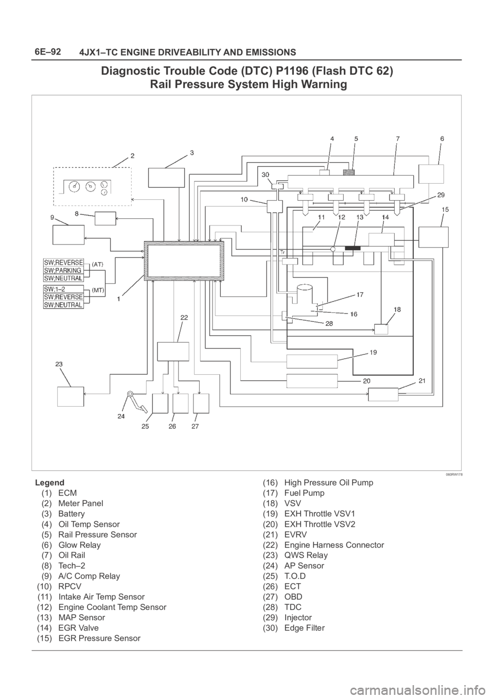
Diagnostic Trouble Code (DTC) P1196 (Flash DTC 62)
Rail Pressure System High Warning
060RW178
Legend
(1) ECM
(2) Meter Panel
(3) Battery
(4) Oil Temp Sensor
(5) Rail Pressure Sensor
(6) Glow Relay
(7) Oil Rail
(8) Tech–2
(9) A/C Comp Relay
(10) RPCV
(11) Intake Air Temp Sensor
(12) Engine Coolant Temp Sensor
(13) MAP Sensor
(14) EGR Valve
(15) EGR Pressure Sensor(16) High Pressure Oil Pump
(17) Fuel Pump
(18) VSV
(19) EXH Throttle VSV1
(20) EXH Throttle VSV2
(21) EVRV
(22) Engine Harness Connector
(23) QWS Relay
(24) AP Sensor
(25) T.O.D
(26) ECT
(27) OBD
(28) TDC
(29) Injector
(30) Edge Filter
Page 1986 of 6000
6E–93 4JX1–TC ENGINE DRIVEABILITY AND EMISSIONS
Circuit Description
The rail pressure control valve (RPCV) is built in the high
pressure oil circuit.
RPCV is an important device which is used to control oil
pressure in the HEUI system.
The circuit receives current through Engine 15A fuse from
the battery, current flowing in the order of RPCV.
Action Taken When the DTC Sets
The ECM will store conditions which were present
when the DTC was set as Freeze Frame and in the
Failure Records data.
Conditions for Clearing the MIL/DTC
DTC P1196 can be cleared by using the Tech 2 “Clear
Info” function or by disconnecting the ECM battery
feed.
Diagnostic Aids
Check for the following conditions:
Poor connection at ECM – Inspect harness connectors
for backed-out terminals, improper mating, broken
locks, improperly formed or damaged terminals, and
poor terminal-to-wire connection.
Damaged harness – Inspect the wiring harness for
damage. If the harness appears to be OK, observe the
Rail Pressure Control display on the Tech 2 while
moving connectors and wiring harnesses related to the
Rail Pressure Control. A change in the Rail Pressure
Control display will indicate the location of the fault.
If DTC P1196 cannot be duplicated, the information
included in the Failure Records data can be useful in
determining vehicle mileage since the DTC was last set.
If it is determined that the DTC occurs intermittently.
Test Description
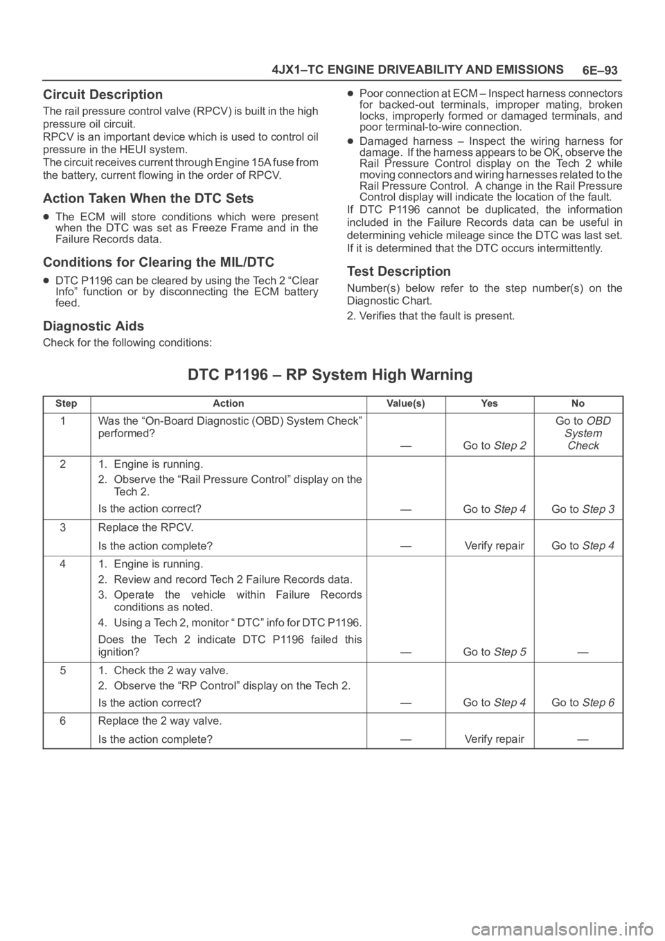
Number(s) below refer to the step number(s) on the
Diagnostic Chart.
2. Verifies that the fault is present.
DTC P1196 – RP System High Warning
StepActionVa l u e ( s )Ye sNo
1Was the “On-Board Diagnostic (OBD) System Check”
performed?
—Go to Step 2
Go to OBD
System
Check
21. Engine is running.
2. Observe the “Rail Pressure Control” display on the
Te c h 2 .
Is the action correct?
—Go to Step 4Go to Step 3
3Replace the RPCV.
Is the action complete?
—Verify repairGo to Step 4
41. Engine is running.
2. Review and record Tech 2 Failure Records data.
3. Operate the vehicle within Failure Records
conditions as noted.
4. Using a Tech 2, monitor “ DTC” info for DTC P1196.
Does the Tech 2 indicate DTC P1196 failed this
ignition?
—Go to Step 5—
51. Check the 2 way valve.
2. Observe the “RP Control” display on the Tech 2.
Is the action correct?
—Go to Step 4Go to Step 6
6Replace the 2 way valve.
Is the action complete?
—Verify repair—
Page 2070 of 6000
6E–177 4JX1–TC ENGINE DRIVEABILITY AND EMISSIONS
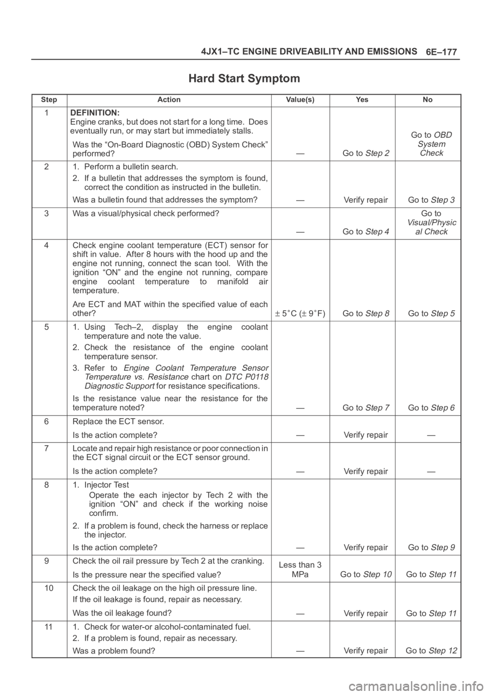
Hard Start Symptom
StepActionVa l u e ( s )Ye sNo
1DEFINITION:
Engine cranks, but does not start for a long time. Does
eventually run, or may start but immediately stalls.
Was the “On-Board Diagnostic (OBD) System Check”
performed?
—Go to Step 2
Go to OBD
System
Check
21. Perform a bulletin search.
2. If a bulletin that addresses the symptom is found,
correct the condition as instructed in the bulletin.
Was a bulletin found that addresses the symptom?
—Verify repairGo to Step 3
3Was a visual/physical check performed?
—Go to Step 4
Go to
Visual/Physic
al Check
4Check engine coolant temperature (ECT) sensor for
shift in value. After 8 hours with the hood up and the
engine not running, connect the scan tool. With the
ignition “ON” and the engine not running, compare
engine coolant temperature to manifold air
temperature.
Are ECT and MAT within the specified value of each
other?
5C ( 9F)Go to Step 8Go to Step 5
51. Using Tech–2, display the engine coolant
temperature and note the value.
2. Check the resistance of the engine coolant
temperature sensor.
3. Refer to
Engine Coolant Temperature Sensor
Temperature vs. Resistance
chart on DTC P0118
Diagnostic Support
for resistance specifications.
Is the resistance value near the resistance for the
temperature noted?
—Go to Step 7Go to Step 6
6Replace the ECT sensor.
Is the action complete?
—Verify repair—
7Locate and repair high resistance or poor connection in
the ECT signal circuit or the ECT sensor ground.
Is the action complete?
—Verify repair—
81. Injector Test
Operate the each injector by Tech 2 with the
ignition “ON” and check if the working noise
confirm.
2. If a problem is found, check the harness or replace
the injector.
Is the action complete?
—Verify repairGo to Step 9
9Check the oil rail pressure by Tech 2 at the cranking.
Is the pressure near the specified value?Less than 3
MPa
Go to Step 10Go to Step 11
10Check the oil leakage on the high oil pressure line.
If the oil leakage is found, repair as necessary.
Was the oil leakage found?
—Verify repairGo to Step 11
111. Check for water-or alcohol-contaminated fuel.
2. If a problem is found, repair as necessary.
Was a problem found?
—Verify repairGo to Step 12
Page 2078 of 6000
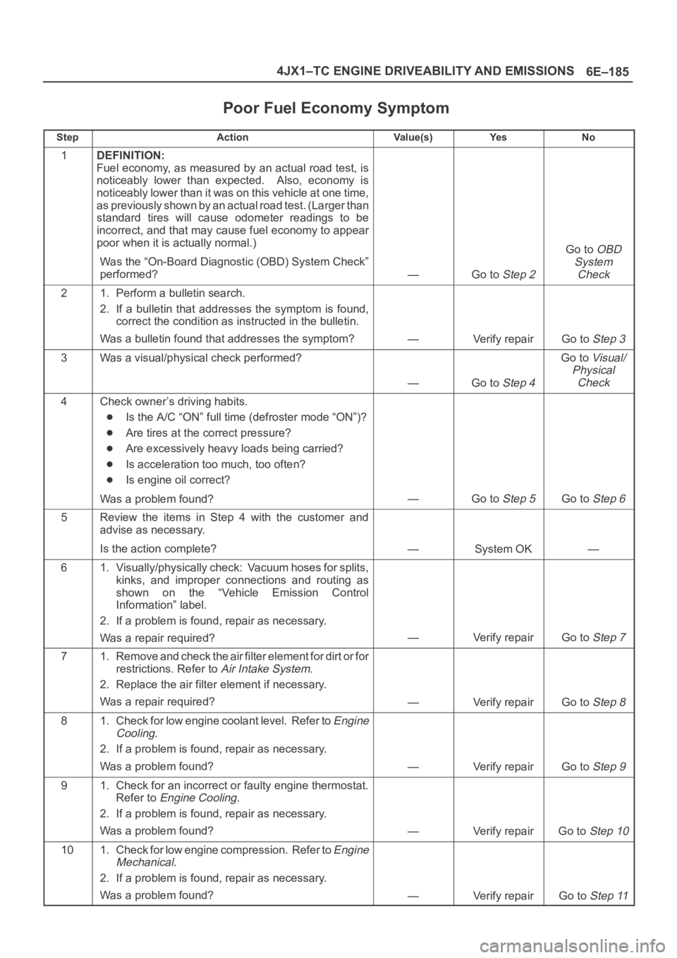
6E–185 4JX1–TC ENGINE DRIVEABILITY AND EMISSIONS
Poor Fuel Economy Symptom
StepActionVa l u e ( s )Ye sNo
1DEFINITION:
Fuel economy, as measured by an actual road test, is
noticeably lower than expected. Also, economy is
noticeably lower than it was on this vehicle at one time,
as previously shown by an actual road test. (Larger than
standard tires will cause odometer readings to be
incorrect, and that may cause fuel economy to appear
poor when it is actually normal.)
Was the “On-Board Diagnostic (OBD) System Check”
performed?
—Go to Step 2
Go to OBD
System
Check
21. Perform a bulletin search.
2. If a bulletin that addresses the symptom is found,
correct the condition as instructed in the bulletin.
Was a bulletin found that addresses the symptom?
—Verify repairGo to Step 3
3Was a visual/physical check performed?
—Go to Step 4
Go to Visual/
Physical
Check
4Check owner’s driving habits.
Is the A/C “ON” full time (defroster mode “ON”)?
Are tires at the correct pressure?
Are excessively heavy loads being carried?
Is acceleration too much, too often?
Is engine oil correct?
Was a problem found?
—Go to Step 5Go to Step 6
5Review the items in Step 4 with the customer and
advise as necessary.
Is the action complete?
—System OK—
61. Visually/physically check: Vacuum hoses for splits,
kinks, and improper connections and routing as
shown on the “Vehicle Emission Control
Information” label.
2. If a problem is found, repair as necessary.
Was a repair required?
—Verify repairGo to Step 7
71. Remove and check the air filter element for dirt or for
restrictions. Refer to
Air Intake System.
2. Replace the air filter element if necessary.
Was a repair required?
—Verify repairGo to Step 8
81. Check for low engine coolant level. Refer to Engine
Cooling
.
2. If a problem is found, repair as necessary.
Was a problem found?
—Verify repairGo to Step 9
91. Check for an incorrect or faulty engine thermostat.
Refer to
Engine Cooling.
2. If a problem is found, repair as necessary.
Was a problem found?
—Verify repairGo to Step 10
101. Check for low engine compression. Refer to Engine
Mechanical
.
2. If a problem is found, repair as necessary.
Was a problem found?
—Verify repairGo to Step 11
Page 2087 of 6000
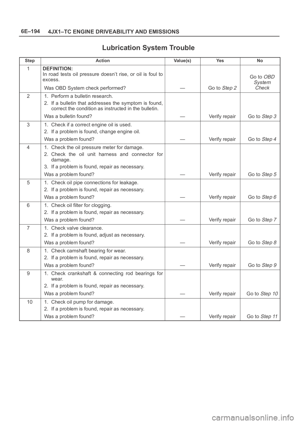
6E–194
4JX1–TC ENGINE DRIVEABILITY AND EMISSIONS
Lubrication System Trouble
StepActionVa l u e ( s )Ye sNo
1DEFINITION:
In road tests oil pressure doesn’t rise, or oil is foul to
excess.
Was OBD System check performed?
—Go to Step 2
Go to OBD
System
Check
21. Perform a bulletin research.
2. If a bulletin that addresses the symptom is found,
correct the condition as instructed in the bulletin.
Was a bulletin found?
—Verify repairGo to Step 3
31. Check if a correct engine oil is used.
2. If a problem is found, change engine oil.
Was a problem found?
—Verify repairGo to Step 4
41. Check the oil pressure meter for damage.
2. Check the oil unit harness and connector for
damage.
3. If a problem is found, repair as necessary.
Was a problem found?
—Verify repairGo to Step 5
51. Check oil pipe connections for leakage.
2. If a problem is found, repair as necessary.
Was a problem found?
—Verify repairGo to Step 6
61. Check oil filter for clogging.
2. If a problem is found, repair as necessary.
Was a problem found?
—Verify repairGo to Step 7
71. Check valve clearance.
2. If a problem is found, adjust as necessary.
Was a problem found?
—Verify repairGo to Step 8
81. Check camshaft bearing for wear.
2. If a problem is found, repair as necessary.
Was a problem found?
—Verify repairGo to Step 9
91. Check crankshaft & connecting rod bearings for
wear.
2. If a problem is found, repair as necessary.
Was a problem found?
—Verify repairGo to Step 10
101. Check oil pump for damage.
2. If a problem is found, repair as necessary.
Was a problem found?
—Verify repairGo to Step 11
Page 2109 of 6000
6E–216
4JX1–TC ENGINE DRIVEABILITY AND EMISSIONS
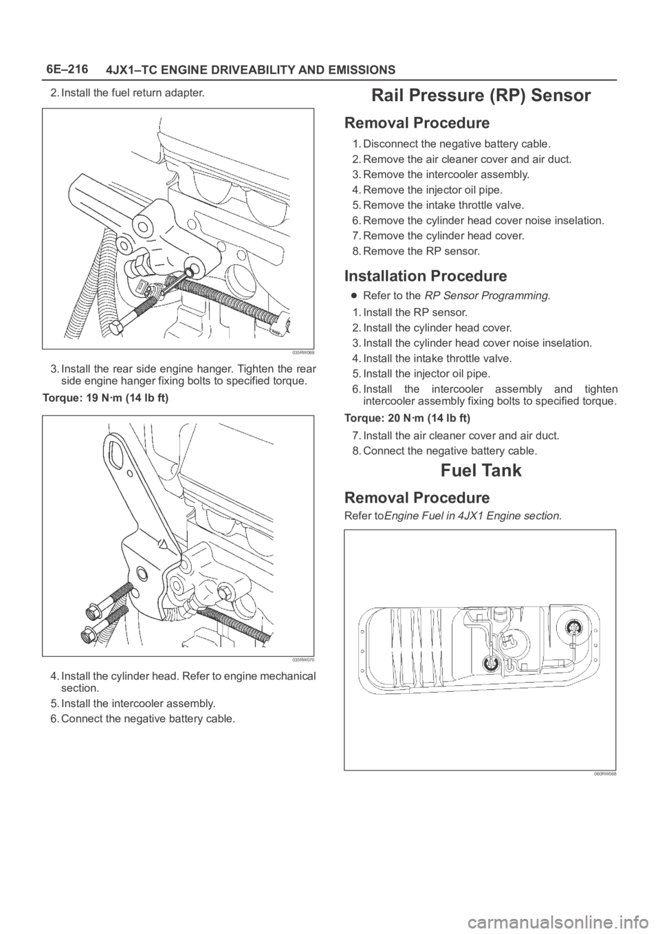
2. Install the fuel return adapter.
035RW069
3. Install the rear side engine hanger. Tighten the rear
side engine hanger fixing bolts to specified torque.
Torque: 19 Nꞏm (14 lb ft)
035RW070
4. Install the cylinder head. Refer to engine mechanical
section.
5. Install the intercooler assembly.
6. Connect the negative battery cable.
Rail Pressure (RP) Sensor
Removal Procedure
1. Disconnect the negative battery cable.
2. Remove the air cleaner cover and air duct.
3. Remove the intercooler assembly.
4. Remove the injector oil pipe.
5. Remove the intake throttle valve.
6. Remove the cylinder head cover noise inselation.
7. Remove the cylinder head cover.
8. Remove the RP sensor.
Installation Procedure
Refer to the RP Sensor Programming.
1. Install the RP sensor.
2. Install the cylinder head cover.
3. Install the cylinder head cover noise inselation.
4. Install the intake throttle valve.
5. Install the injector oil pipe.
6. Install the intercooler assembly and tighten
intercooler assembly fixing bolts to specified torque.
Torque: 20 Nꞏm (14 lb ft)
7. Install the air cleaner cover and air duct.
8. Connect the negative battery cable.
Fuel Tank
Removal Procedure
Refer toEngine Fuel in 4JX1 Engine section.
060RW068
Page 2119 of 6000
6E–226
4JX1–TC ENGINE DRIVEABILITY AND EMISSIONS
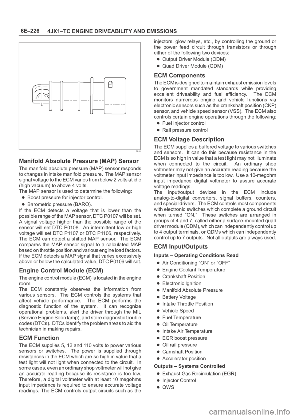
0018
Manifold Absolute Pressure (MAP) Sensor
The manifold absolute pressure (MAP) sensor responds
to changes in intake manifold pressure. The MAP sensor
signal voltage to the ECM varies from below 2 volts at idle
(high vacuum) to above 4 volts.
The MAP sensor is used to determine the following:
Boost pressure for injector control.
Barometric pressure (BARO).
If the ECM detects a voltage that is lower than the
possible range of the MAP sensor, DTC P0107 will be set.
A signal voltage higher than the possible range of the
sensor will set DTC P0108. An intermittent low or high
voltage will set DTC P1107 or DTC P1106, respectively.
The ECM can detect a shifted MAP sensor. The ECM
compares the MAP sensor signal to a calculated MAP
based on throttle position and various engine load factors.
If the ECM detects a MAP signal that varies excessively
above or below the calculated value, DTC P0106 will set.
Engine Control Module (ECM)
The engine control module (ECM) is located in the engine
room.
The ECM constantly observes the information from
various sensors. The ECM controls the systems that
affect vehicle performance. The ECM performs the
diagnostic function of the system. It can recognize
operational problems, alert the driver through the MIL
(Service Engine Soon lamp), and store diagnostic trouble
codes (DTCs). DTCs identify the problem areas to aid the
technician in making repairs.
ECM Function
The ECM supplies 5, 12 and 110 volts to power various
sensors or switches. The power is supplied through
resistances in the ECM which are so high in value that a
test light will not light when connected to the circuit. In
some cases, even an ordinary shop voltmeter will not give
an accurate reading because its resistance is too low.
Therefore, a digital voltmeter with at least 10 megohms
input impedance is required to ensure accurate voltage
readings. The ECM controls output circuits such as theinjectors, glow relays, etc., by controlling the ground or
the power feed circuit through transistors or through
either of the following two devices:
Output Driver Module (ODM)
Quad Driver Module (QDM)
ECM Components
The ECM is designed to maintain exhaust emission levels
to government mandated standards while providing
excellent driveability and fuel efficiency. The ECM
monitors numerous engine and vehicle functions via
electronic sensors such as the crankshaft position (CKP)
sensor, and vehicle speed sensor (VSS). The ECM also
controls certain engine operations through the following:
Fuel injector control
Rail pressure control
ECM Voltage Description
The ECM supplies a buffered voltage to various switches
and sensors. It can do this because resistance in the
ECM is so high in value that a test light may not illuminate
when connected to the circuit. An ordinary shop
voltmeter may not give an accurate reading because the
voltmeter input impedance is too low. Use a 10-megohm
input impedance digital voltmeter to assure accurate
voltage readings.
The input/output devices in the ECM include
analog-to-digital converters, signal buffers, counters,
and special drivers. The ECM controls most components
with electronic switches which complete a ground circuit
when turned “ON.” These switches are arranged in
groups of 4 and 7, called either a surface-mounted quad
driver module (QDM), which can independently control up
to 4 output terminals, or QDMs which can independently
control up to 7 outputs. Not all outputs are always used.
ECM Input/Outputs
Inputs – Operating Conditions Read
Air Conditioning “ON” or “OFF”
Engine Coolant Temperature
Crankshaft Position
Electronic Ignition
Manifold Absolute Pressure
Battery Voltage
Intake Throttle Position
Vehicle Speed
Fuel Temperature
Oil Temperature
Intake Air Temperature
EGR boost pressure
Oil rail pressure
Camshaft Position
Accelerator position
Outputs – Systems Controlled
Exhaust Gas Recirculation (EGR)
Injector Control
QWS