1998 OPEL FRONTERA oil pressure
[x] Cancel search: oil pressurePage 2172 of 6000
7A–18
AUTOMATIC TRANSMISSION (4L30–E)
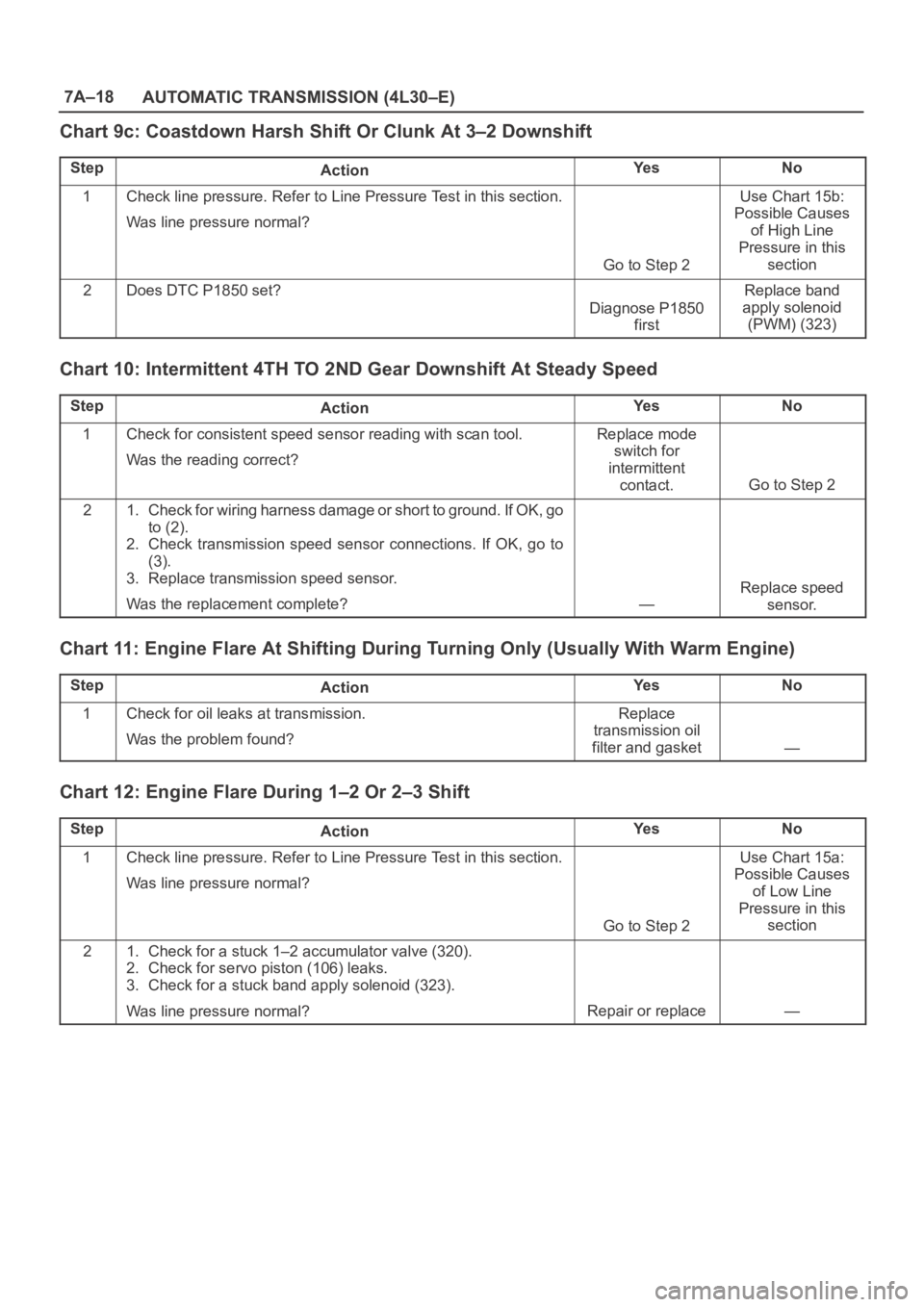
Chart 9c: Coastdown Harsh Shift Or Clunk At 3–2 Downshift
StepActionYe sNo
1Check line pressure. Refer to Line Pressure Test in this section.
Was line pressure normal?
Go to Step 2
Use Chart 15b:
Possible Causes
of High Line
Pressure in this
section
2Does DTC P1850 set?
Diagnose P1850
first
Replace band
apply solenoid
(PWM) (323)
Chart 10: Intermittent 4TH TO 2ND Gear Downshift At Steady Speed
StepActionYe sNo
1Check for consistent speed sensor reading with scan tool.
Was the reading correct?Replace mode
switch for
intermittent
contact.
Go to Step 2
21. Check for wiring harness damage or short to ground. If OK, go
to (2).
2. Check transmission speed sensor connections. If OK, go to
(3).
3. Replace transmission speed sensor.
Was the replacement complete?
—
Replace speed
sensor.
Chart 11: Engine Flare At Shifting During Turning Only (Usually With Warm Engine)
StepActionYe sNo
1Check for oil leaks at transmission.
Was the problem found?Replace
transmission oil
filter and gasket
—
Chart 12: Engine Flare During 1–2 Or 2–3 Shift
StepActionYe sNo
1Check line pressure. Refer to Line Pressure Test in this section.
Was line pressure normal?
Go to Step 2
Use Chart 15a:
Possible Causes
of Low Line
Pressure in this
section
21. Check for a stuck 1–2 accumulator valve (320).
2. Check for servo piston (106) leaks.
3. Check for a stuck band apply solenoid (323).
Was line pressure normal?
Repair or replace—
Page 2174 of 6000
7A–20
AUTOMATIC TRANSMISSION (4L30–E)
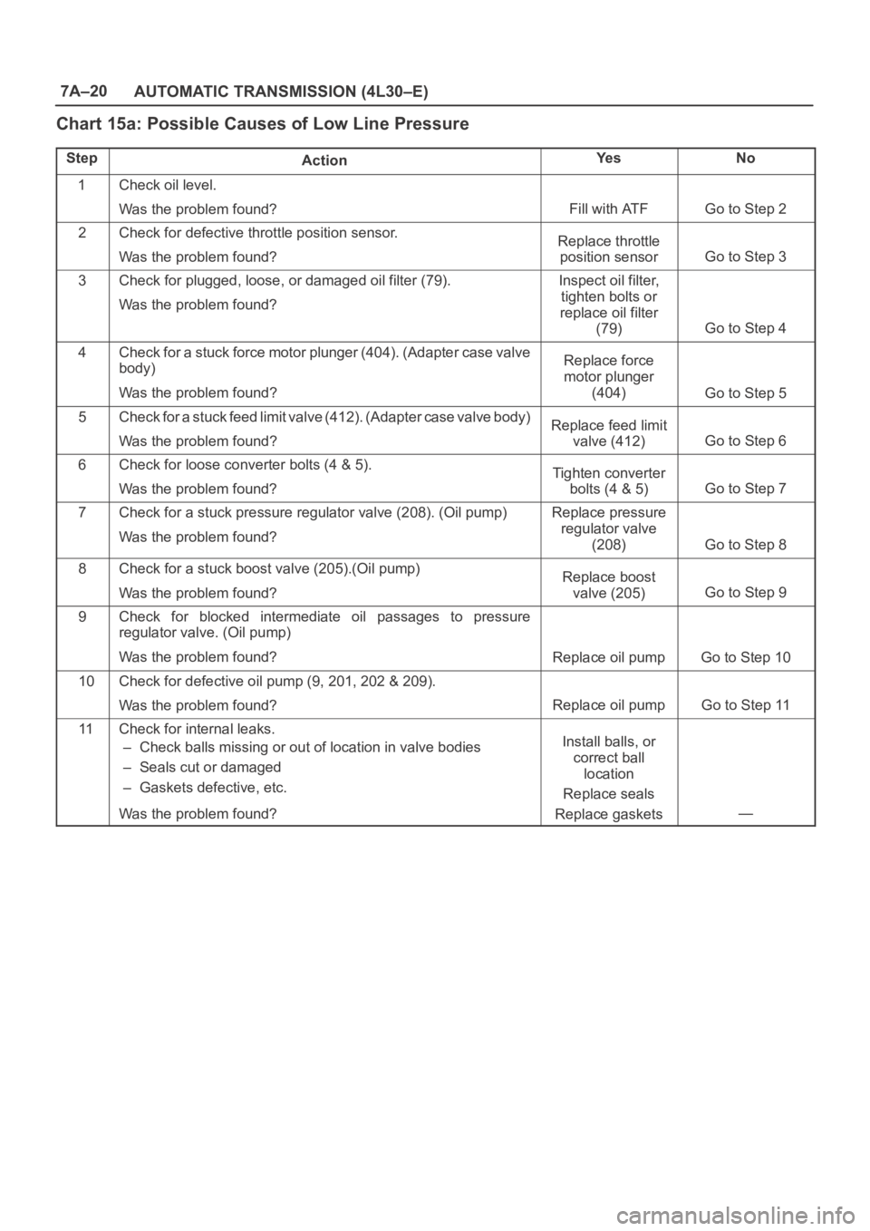
Chart 15a: Possible Causes of Low Line Pressure
StepActionYe sNo
1Check oil level.
Was the problem found?
Fill with ATFGo to Step 2
2Check for defective throttle position sensor.
Was the problem found?Replace throttle
position sensor
Go to Step 3
3Check for plugged, loose, or damaged oil filter (79).
Was the problem found?Inspect oil filter,
tighten bolts or
replace oil filter
(79)
Go to Step 4
4Check for a stuck force motor plunger (404). (Adapter case valve
body)
Was the problem found?Replace force
motor plunger
(404)
Go to Step 5
5Check for a stuck feed limit valve (412). (Adapter case valve body)
Was the problem found?Replace feed limit
valve (412)
Go to Step 6
6Check for loose converter bolts (4 & 5).
Was the problem found?Tighten converter
bolts (4 & 5)
Go to Step 7
7Check for a stuck pressure regulator valve (208). (Oil pump)
Was the problem found?Replace pressure
regulator valve
(208)
Go to Step 8
8Check for a stuck boost valve (205).(Oil pump)
Was the problem found?Replace boost
valve (205)
Go to Step 9
9Check for blocked intermediate oil passages to pressure
regulator valve. (Oil pump)
Was the problem found?
Replace oil pumpGo to Step 10
10Check for defective oil pump (9, 201, 202 & 209).
Was the problem found?
Replace oil pumpGo to Step 11
11Check for internal leaks.
– Check balls missing or out of location in valve bodies
– Seals cut or damaged
– Gaskets defective, etc.
Was the problem found?Install balls, or
correct ball
location
Replace seals
Replace gaskets
—
Page 2175 of 6000

7A–21 AUTOMATIC TRANSMISSION (4L30–E)
Chart 15b: Possible Causes Of High Line Pressure
NOTE: If transmission is operating in backup mode, high
line pressure will be present.
Step
ActionYe sNo
1Check for defective throttle position sensor.
Was the problem found?Replace throttle
position sensor.
Go to Step 2.
2Check for a stuck force motor plunger (404). (Open
circuit/intermittent) (Adapter case valve body)
Was the problem found?Replace force
motor plunger
(404)
Go to Step 3
3Check for a stuck feed limit valve (412). (Adapter case valve body)
Was the problem found?Replace force
motor plunger
(412)
Go to Step 4
4Check converter bolts (4 & 5).
Was the problem found?Tighten converter
bolts (4 & 5)
Go to Step 5
5Check for a stuck pressure regulator valve (208). (Oil pump)
Was the problem found?Replace pressure
regulator valve
(208)
Go to Step 6
6Check for a stuck boost valve (205). (Oil pump)
Was the problem found?Replace boost
valve (205)
Go to Step 7
7Check for internal leaks.
– Check balls missing or out of location in valve bodies
– Seals cut or missing
– Gaskets defective, etc.
Was the problem found?Install balls, or
correct ball
location
Replace seals
Replace gaskets
—
Page 2176 of 6000
7A–22
AUTOMATIC TRANSMISSION (4L30–E)
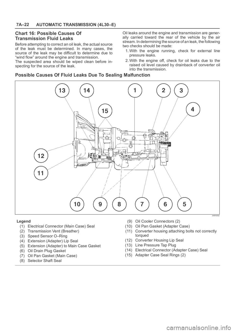
Chart 16: Possible Causes Of
Transmission Fluid Leaks
Before attempting to correct an oil leak, the actual source
of the leak must be determined. In many cases, the
source of the leak may be difficult to determine due to
“wind flow” around the engine and transmission.
The suspected area should be wiped clean before in-
specting for the source of the leak.Oil leaks around the engine and transmission are gener-
ally carried toward the rear of the vehicle by the air
stream. In determining the source of an leak, the following
two checks should be made:
1. With the engine running, check for external line
pressure leaks.
2. With the engine off, check for oil leaks due to the
raised oil level caused by drainback of converter oil
into the transmission.
Possible Causes Of Fluid Leaks Due To Sealing Malfunction
240RS002
Legend
(1) Electrical Connector (Main Case) Seal
(2) Transmission Vent (Breather)
(3) Speed Sensor O–Ring
(4) Extension (Adapter) Lip Seal
(5) Extension (Adapter) to Main Case Gasket
(6) Oil Drain Plug Gasket
(7) Oil Pan Gasket (Main Case)
(8) Selector Shaft Seal(9) Oil Cooler Connectors (2)
(10) Oil Pan Gasket (Adapter Case)
(11) Converter housing attaching bolts not correctly
torqued
(12) Converter Housing Lip Seal
(13) Line Pressure Tap Plug
(14) Electrical Connector (Adapter Case) Seal
(15) Adapter Case Seal Rings (2)
Page 2177 of 6000
7A–23 AUTOMATIC TRANSMISSION (4L30–E)
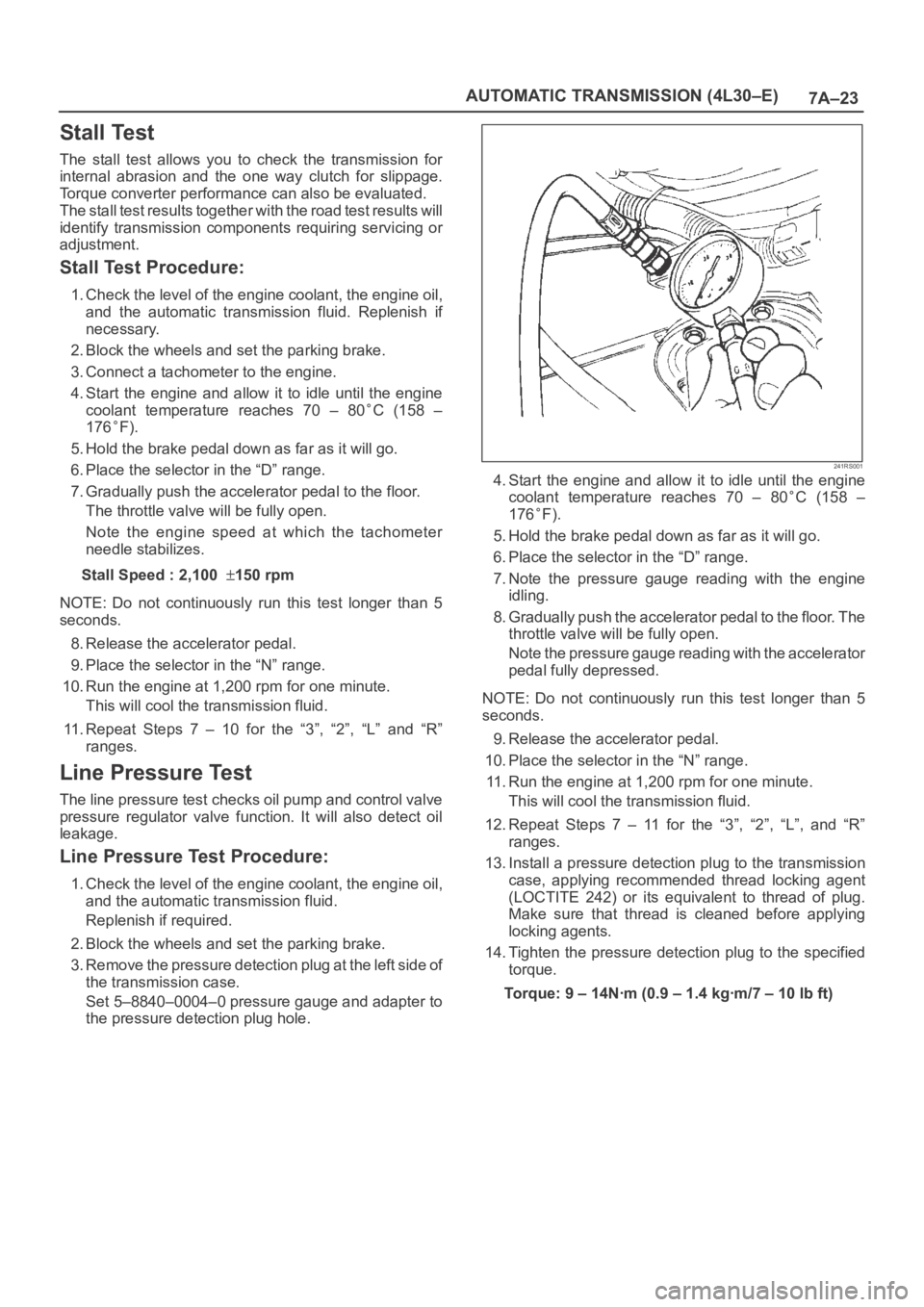
Stall Test
The stall test allows you to check the transmission for
internal abrasion and the one way clutch for slippage.
Torque converter performance can also be evaluated.
The stall test results together with the road test results will
identify transmission components requiring servicing or
adjustment.
Stall Test Procedure:
1. Check the level of the engine coolant, the engine oil,
and the automatic transmission fluid. Replenish if
necessary.
2. Block the wheels and set the parking brake.
3. Connect a tachometer to the engine.
4. Start the engine and allow it to idle until the engine
coolant temperature reaches 70 – 80
C (158 –
176
F).
5. Hold the brake pedal down as far as it will go.
6. Place the selector in the “D” range.
7. Gradually push the accelerator pedal to the floor.
The throttle valve will be fully open.
Note the engine speed at which the tachometer
needle stabilizes.
Stall Speed : 2,100
150 rpm
NOTE: Do not continuously run this test longer than 5
seconds.
8. Release the accelerator pedal.
9. Place the selector in the “N” range.
10. Run the engine at 1,200 rpm for one minute.
This will cool the transmission fluid.
11. Repeat Steps 7 – 10 for the “3”, “2”, “L” and “R”
ranges.
Line Pressure Test
The line pressure test checks oil pump and control valve
pressure regulator valve function. It will also detect oil
leakage.
Line Pressure Test Procedure:
1. Check the level of the engine coolant, the engine oil,
and the automatic transmission fluid.
Replenish if required.
2. Block the wheels and set the parking brake.
3. Remove the pressure detection plug at the left side of
the transmission case.
Set 5–8840–0004–0 pressure gauge and adapter to
the pressure detection plug hole.
241RS001
4. Start the engine and allow it to idle until the engine
coolant temperature reaches 70 – 80
C (158 –
176
F).
5. Hold the brake pedal down as far as it will go.
6. Place the selector in the “D” range.
7. Note the pressure gauge reading with the engine
idling.
8. Gradually push the accelerator pedal to the floor. The
throttle valve will be fully open.
Note the pressure gauge reading with the accelerator
pedal fully depressed.
NOTE: Do not continuously run this test longer than 5
seconds.
9. Release the accelerator pedal.
10. Place the selector in the “N” range.
11. Run the engine at 1,200 rpm for one minute.
This will cool the transmission fluid.
12. Repeat Steps 7 – 11 for the “3”, “2”, “L”, and “R”
ranges.
13. Install a pressure detection plug to the transmission
case, applying recommended thread locking agent
(LOCTITE 242) or its equivalent to thread of plug.
Make sure that thread is cleaned before applying
locking agents.
14. Tighten the pressure detection plug to the specified
torque.
Torque:9–14Nꞏm(0.9–1.4kgꞏm/7–10lbft)
Page 2201 of 6000
7A–47 AUTOMATIC TRANSMISSION (4L30–E)
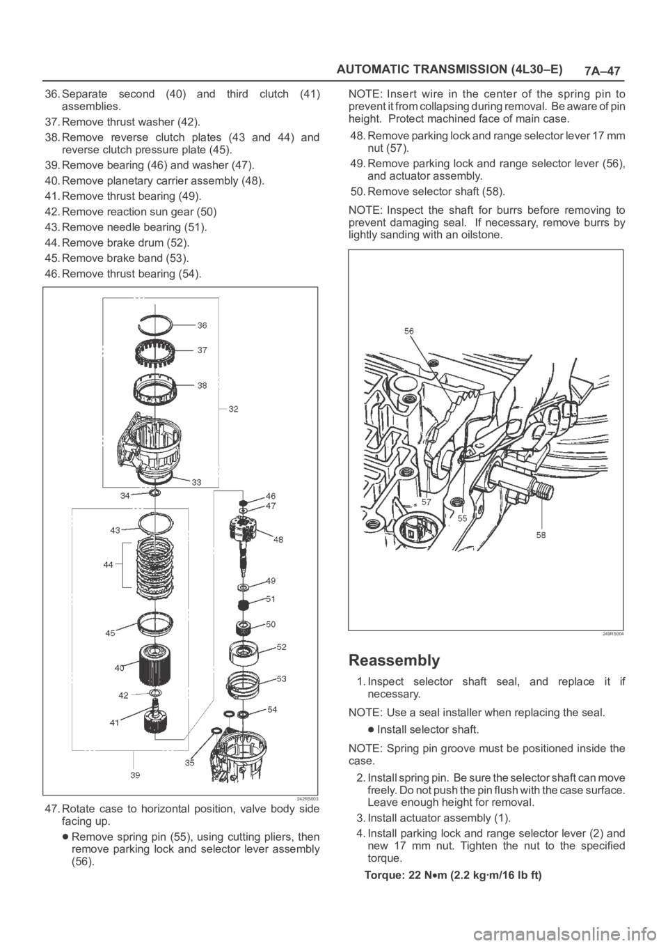
36. Separate second (40) and third clutch (41)
assemblies.
37. Remove thrust washer (42).
38. Remove reverse clutch plates (43 and 44) and
reverse clutch pressure plate (45).
39. Remove bearing (46) and washer (47).
40. Remove planetary carrier assembly (48).
41. Remove thrust bearing (49).
42. Remove reaction sun gear (50)
43. Remove needle bearing (51).
44. Remove brake drum (52).
45. Remove brake band (53).
46. Remove thrust bearing (54).
242RS003
47. Rotate case to horizontal position, valve body side
facing up.
Remove spring pin (55), using cutting pliers, then
remove parking lock and selector lever assembly
(56).NOTE: Insert wire in the center of the spring pin to
prevent it from collapsing during removal. Be aware of pin
height. Protect machined face of main case.
48. Remove parking lock and range selector lever 17 mm
nut (57).
49. Remove parking lock and range selector lever (56),
and actuator assembly.
50. Remove selector shaft (58).
NOTE: Inspect the shaft for burrs before removing to
prevent damaging seal. If necessary, remove burrs by
lightly sanding with an oilstone.
249RS004
Reassembly
1. Inspect selector shaft seal, and replace it if
necessary.
NOTE: Use a seal installer when replacing the seal.
Install selector shaft.
NOTE: Spring pin groove must be positioned inside the
case.
2. Install spring pin. Be sure the selector shaft can move
freely. Do not push the pin flush with the case surface.
Leave enough height for removal.
3. Install actuator assembly (1).
4. Install parking lock and range selector lever (2) and
new 17 mm nut. Tighten the nut to the specified
torque.
To r q u e : 2 2 N
m (2.2 kgꞏm/16 lb ft)
Page 2212 of 6000
7A–58
AUTOMATIC TRANSMISSION (4L30–E)
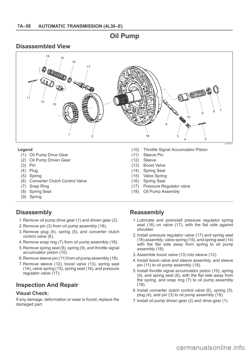
Oil Pump
Disassembled View
241RS014
Legend
(1) Oil Pump Drive Gear
(2) Oil Pump Driven Gear
(3) Pin
(4) Plug
(5) Spring
(6) Converter Clutch Control Valve
(7) Snap Ring
(8) Spring Seat
(9) Spring(10) Throttle Signal Accumulator Piston
(11) Sleeve Pin
(12) Sleeve
(13) Boost Valve
(14) Spring Seat
(15) Valve Spring
(16) Spring Seat
(17) Pressure Regulator valve
(18) Oil Pump Assembly
Disassembly
1. Remove oil pump drive gear (1) and driven gear (2).
2. Remove pin (3) from oil pump assembly (18).
3. Remove plug (4), spring (5), and converter clutch
control valve (6).
4. Remove snap ring (7) from oil pump assembly (18).
5. Remove spring seat (8), spring (9), and throttle signal
accumulator piston (10).
6. Remove sleeve pin (11) from oil pump assembly (18).
7. Remove sleeve (12), boost valve (13), spring seat
(14), valve spring (15), spring seat (16), and pressure
regulator valve (17).
Inspection And Repair
Visual Check:
If any damage, deformation or wear is found, replace the
damaged part.
Reassembly
1. Lubricate and preinstall pressure regulator spring
seat (16) on valve (17), with the flat side against
shoulder.
2. Install pressure regulator valve (17) and spring seat
(16) assembly, valve spring (15), and spring seat (14)
with the flat side away from spring to oil pump
assembly (18).
3. Assemble boost valve (13) into sleeve (12).
4. Install boost valve and sleeve assembly, and sleeve
pin (11) to oil pump assembly (18).
5. Install throttle signal accumulator piston (10), spring
(9), and spring seat (8), with the flat side away from
the spring, and snap ring (7) to oil pump assembly
(18).
6. Install converter clutch control valve (6), spring (5),
plug (4), and pin (3) to oil pump assembly (18).
7. Install oil pump driven gear (2) and drive gear (1).
Page 2214 of 6000
7A–60
AUTOMATIC TRANSMISSION (4L30–E)
10. Remove retainer (13), 2–3 shift valve (14), and spring
(15).
11. Remove spring pin (16), plug (17), spring (18), and
low pressure control valve (19).
12. Remove spring pin (20), plug (21), and band control
screen assembly (22).
13. Remove spring pin (23), plug (24), 1–2 accumulator
valve (25), and 1–2 accumulator control valve (26).
14. Remove check ball (27) from valve body (28).
Inspection And Repair
Inspect for the following, and replace any damaged or
worn parts:
1. Damage or wear to each valve.
2. Damage in oil passeges.
3. Cracks or damage to valve body.
4. Valve operations.
5. Spring fatigue.
Reassembly
1. Install 1–2 accumulator control valve (26), 1–2
accumulator valve (25), plug (24), and spring pin (23).
2. Install band control screen assembly (22), plug (21),
and spring pin (20).
3. Install low pressure control valve (19), spring (18),
plug (17), and spring pin (16).
4. Install spring (15), 2–3 shift valve (14), retainer (13),
solenoid B (12), and spring pin (11).
5. Install spring (10), 1–2/3–4 shift valve (9), retainer (8),
solenoid A (7), and spring pin (6).
6. Install waved washer (5), band control solenoid (3),
and pin (4).
7. Install manual valve (2).
8. Install check ball (27) to valve body (28).
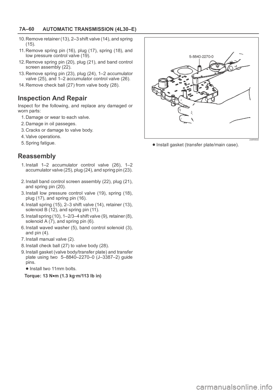
9. Install gasket (valve body/transfer plate) and transfer
plate using two 5–8840–2270–0 (J–3387–2) guide
pins.
Install two 11mm bolts.
Torque: 13 N
m (1.3 kgꞏm/113 lb in)
244RW004
Install gasket (transfer plate/main case).