1998 OPEL FRONTERA oil pressure
[x] Cancel search: oil pressurePage 2237 of 6000
7A–83 AUTOMATIC TRANSMISSION (4L30–E)
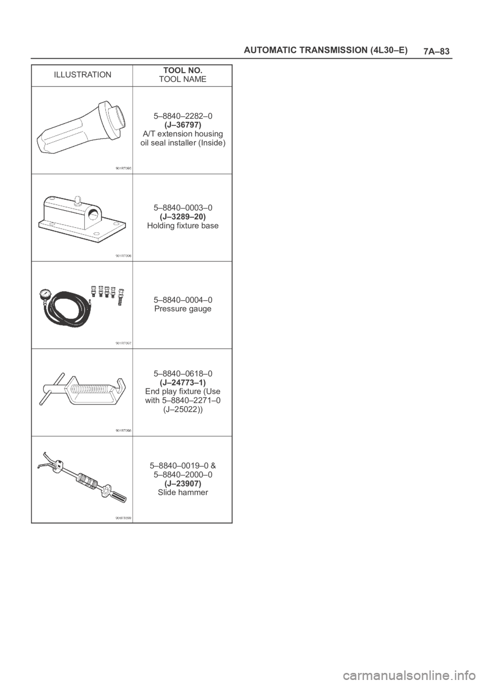
ILLUSTRATIONTOOL NO.
TOOL NAME
5–8840–2282–0
(J–36797)
A/T extension housing
oil seal installer (Inside)
5–8840–0003–0
(J–3289–20)
Holding fixture base
5–8840–0004–0
Pressure gauge
5–8840–0618–0
(J–24773–1)
End play fixture (Use
with 5–8840–2271–0
(J–25022))
5–8840–0019–0 &
5–8840–2000–0
(J–23907)
Slide hammer
Page 2240 of 6000
7A–86
AUTOMATIC TRANSMISSION (4L30–E)
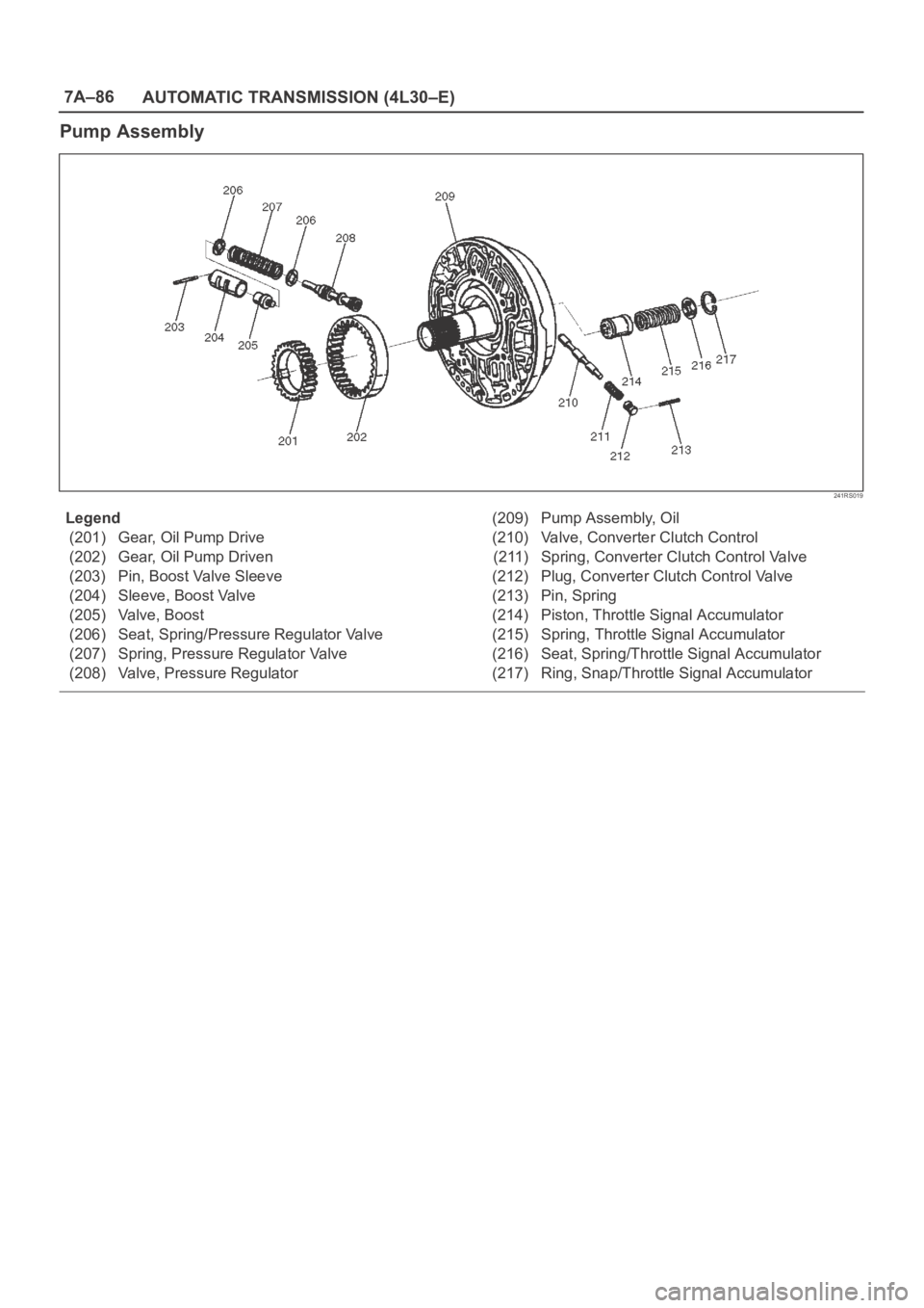
Pump Assembly
241RS019
Legend
(201) Gear, Oil Pump Drive
(202) Gear, Oil Pump Driven
(203) Pin, Boost Valve Sleeve
(204) Sleeve, Boost Valve
(205) Valve, Boost
(206) Seat, Spring/Pressure Regulator Valve
(207) Spring, Pressure Regulator Valve
(208) Valve, Pressure Regulator(209) Pump Assembly, Oil
(210) Valve, Converter Clutch Control
(211) Spring, Converter Clutch Control Valve
(212) Plug, Converter Clutch Control Valve
(213) Pin, Spring
(214) Piston, Throttle Signal Accumulator
(215) Spring, Throttle Signal Accumulator
(216) Seat, Spring/Throttle Signal Accumulator
(217) Ring, Snap/Throttle Signal Accumulator
Page 2251 of 6000
7A1–6
TRANSMISSION CONTROL SYSTEM (4L30–E)
Shift Control
The transmission gear is shifted according to the shift
pattern selected by the driver. In shifting gears, the gear
ratio is controlled by the ON/ OFF signal using the shift
solenoid A and the shift solenoid B.
Band Apply Control
The band apply is controlled when in the 3–2 downshift
(engine overrun prevention) and the garage shift (shock
control).
The band apply solenoid is controlled by the signal from
the Pulse Width Modulation (PWM) to regulate the flow of
the oil.
Torque Converter Clutch Control
The clutch ON/OFF is controlled by moving the converter
clutch valve through shifting Torque Converter Clutch
(TCC) solenoid using the ON/OFF signal.
Line Pressure Control
The throttle signal allows the current signal to be sent to
the force motor. After receiving the current signal, the
force motor activates the pressure regulator valve to
regulate the line pressure.
On–Board Diagnostic System
Several malfunction displays can be stored in the
Powertrain Control Module (PCM) memory, and read out
of it afterward.The serial data lines, which are required for the testing of
the final assembly and the coupling to other electronic
modules, can be regulated by this function.
Fail Safe Mechanism
If there is a problem in the transmission system, the PCM
will go into a “backup” mode.
The vehicle can still be driven, but the driver must use the
select lever to shift gears.
Torque Management Control
The transmission control side sends the absolute spark
advance signal to the engine control side while the
transmission is being shifted. This controls the engine
spark timing in compliance with the vehicle running
condition to reduce the shocks caused by the change of
speed.
ATF Warning Control
The oil temperature sensor detects the ATF oil
temperature to control the oil temperature warning, TCC,
and the winter mode.
ABS Control (If equipped)
When the select lever is at “L” or “R” range, a signal is sent
to the ABS controller as one of the ABS control
conditions.
Page 2255 of 6000
7A1–10
TRANSMISSION CONTROL SYSTEM (4L30–E)
Functions of Input / Output Components
ComponentsFunction
Speed sensor
(fixed to transmission
(T/M))Senses rotation of output shaft and feeds the data to Powertrain Control Module
(PCM).
Throttle position sensor
(TPS)
(fixed to engine)Senses the extent of throttle valve opening and the speed of the throttle valve
lever motion to open the valve. Feeds the data to PCM.
I
N
Brake Switch (SW)
(fixed to brake pedal)Senses whether the driver has pressed the brake pedal or not and feeds the
information to PCM.
N-
P
U
Kickdown SW
(fixed to accelerator pedal)Senses whether the driver has pushed the accelerator pedal fully or not, and
feeds the information to PCM.
U
TMode SW (fixed to T/M)Senses the select lever position, and feeds the information to PCM.
S
I
Power drive SW
(fixed to front console)Senses whether the driver has selected the power mode, and feeds the informa-
tion to PCM.
I
G-T/M oil temp. sensorSenses the T/M oil temperature and feeds the data to PCM
N
A
L
Engine coolant tempera-
ture sensorSenses the engine coolant temperature, and feeds the data to PCM.
LEngine speed signalFeeds the signals monitoring engine speed to PCM from crank angle sensor.
Air conditioning informationSenses whether the air conditioner has been switched on or not, and feeds the
information to PCM.
Winter switch (fixed to front
console)Senses whether the driver has selected the winter mode, and feeds the informa-
tion to PCM.
Cruise controller * (Over-
drive OFF signal)Downshift takes place when Overdrive OFF signal is received from auto cruise
control unit.
S
Shift solenoid A, BSelects shift point and gear position suited to the vehicle running condition on
the basis of PCM output.
O
S
O-
L
Band apply solenoidControls oil flow suited to the vehicle running condition on the basis of PCM out-
put.
O
U
T-
P
E-
N
O
Torque Converter
Clutch solenoidControls clutch engagement/disengagement suited to the vehicle running condi-
tion on the basis of PCM output.
P
U
T
O
I
DForce motor
(Pressure regulator
valve)Adjusts the oil pump delivery pressure to line pressure suited to the vehicle run-
ning condition on the basis of PCM output.
S
I
Power drive mode lampInforms the driver whether the vehicle is in power mode or not.
I
G-Winter drive mode lampInforms the driver whether the vehicle is in winter mode or not.G
N
A
L
T/M monitor lamp
(“CHECK TRANS”)Informs the driver of failure in the system.
LATF warning lampLights when ATF oil temperature rises.
ABS signal *When the select lever is at “Reverse” or “L” range, sends a signal to the ABS
controller as one of the ABS control conditions.
* If equipped
Page 2300 of 6000
TRANSMISSION CONTROL SYSTEM (4L30–E)7A1–55
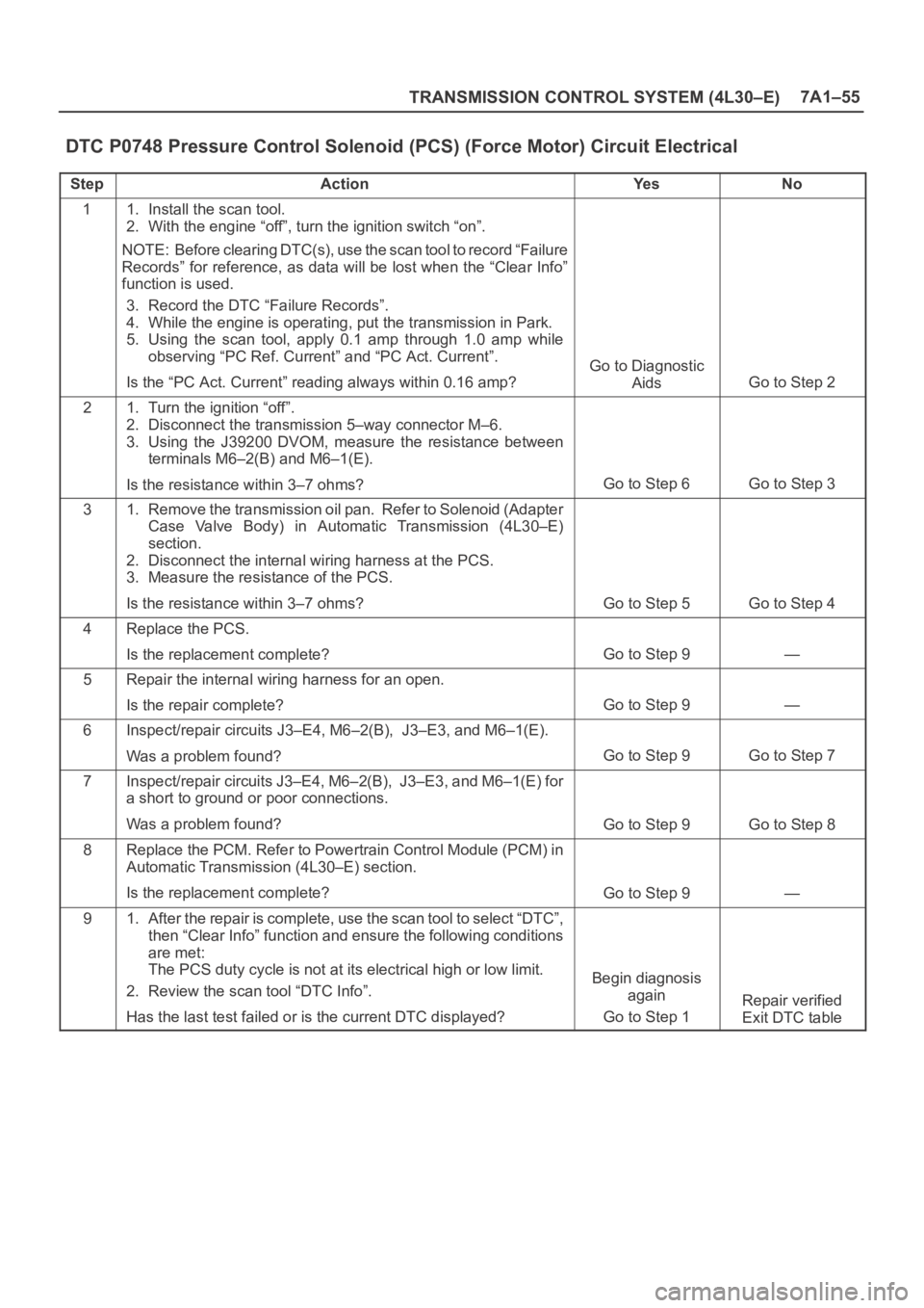
DTC P0748 Pressure Control Solenoid (PCS) (Force Motor) Circuit Electrical
StepActionYe sNo
11. Install the scan tool.
2. With the engine “off”, turn the ignition switch “on”.
NOTE: Before clearing DTC(s), use the scan tool to record “Failure
Records” for reference, as data will be lost when the “Clear Info”
function is used.
3. Record the DTC “Failure Records”.
4. While the engine is operating, put the transmission in Park.
5. Using the scan tool, apply 0.1 amp through 1.0 amp while
observing “PC Ref. Current” and “PC Act. Current”.
Is the “PC Act. Current” reading always within 0.16 amp?
Go to Diagnostic
Aids
Go to Step 2
21. Turn the ignition “off”.
2. Disconnect the transmission 5–way connector M–6.
3. Using the J39200 DVOM, measure the resistance between
terminals M6–2(B) and M6–1(E).
Is the resistance within 3–7 ohms?
Go to Step 6Go to Step 3
31. Remove the transmission oil pan. Refer to Solenoid (Adapter
Case Valve Body) in Automatic Transmission (4L30–E)
section.
2. Disconnect the internal wiring harness at the PCS.
3. Measure the resistance of the PCS.
Is the resistance within 3–7 ohms?
Go to Step 5Go to Step 4
4Replace the PCS.
Is the replacement complete?
Go to Step 9—
5Repair the internal wiring harness for an open.
Is the repair complete?
Go to Step 9—
6Inspect/repair circuits J3–E4, M6–2(B), J3–E3, and M6–1(E).
Was a problem found?
Go to Step 9Go to Step 7
7Inspect/repair circuits J3–E4, M6–2(B), J3–E3, and M6–1(E) for
a short to ground or poor connections.
Was a problem found?
Go to Step 9Go to Step 8
8Replace the PCM. Refer to Powertrain Control Module (PCM) in
Automatic Transmission (4L30–E) section.
Is the replacement complete?
Go to Step 9—
91. After the repair is complete, use the scan tool to select “DTC”,
then “Clear Info” function and ensure the following conditions
are met:
The PCS duty cycle is not at its electrical high or low limit.
2. Review the scan tool “DTC Info”.
Has the last test failed or is the current DTC displayed?
Begin diagnosis
again
Go to Step 1
Repair verified
Exit DTC table
Page 2312 of 6000
TRANSMISSION CONTROL SYSTEM (4L30–E)7A1–67
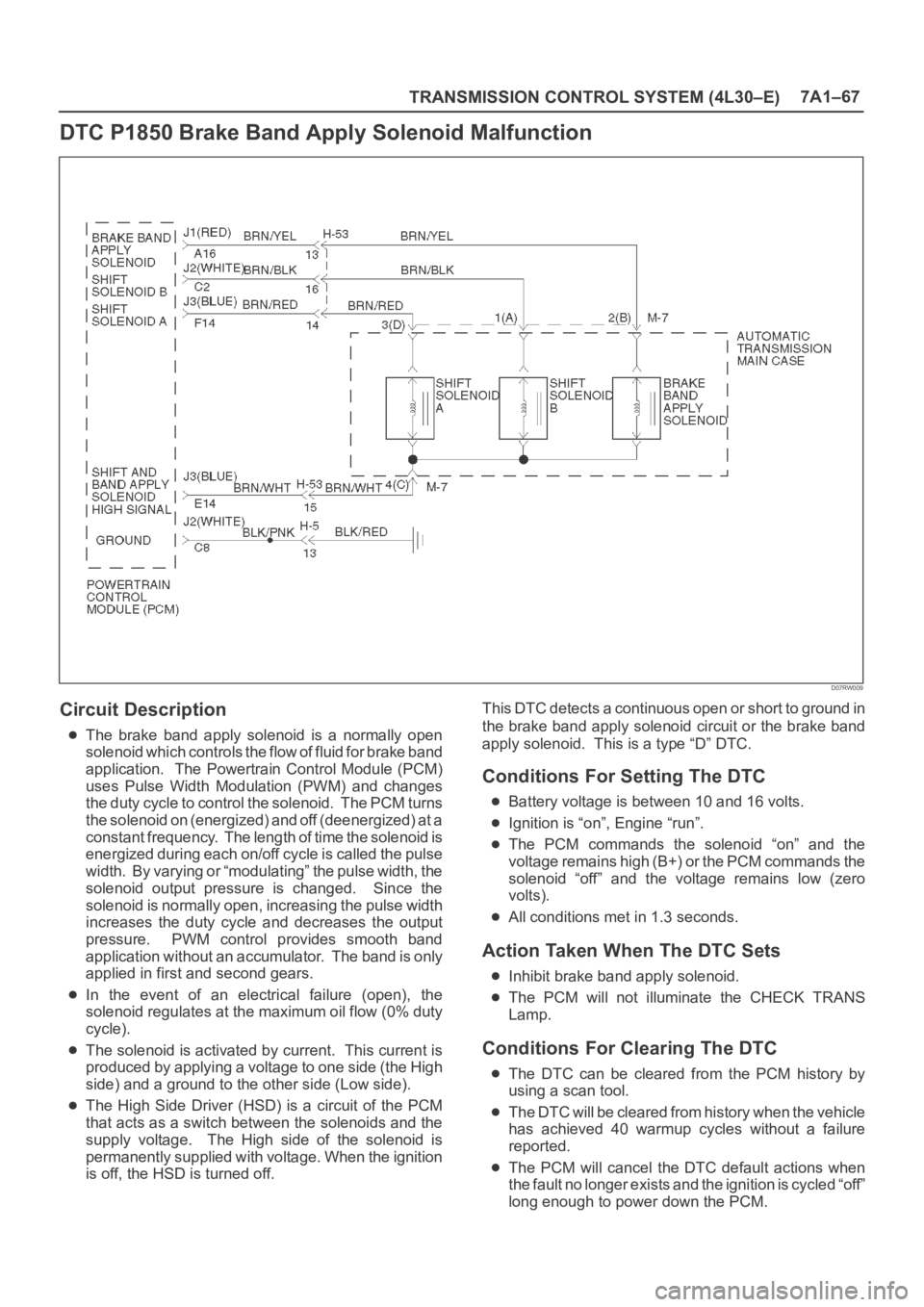
DTC P1850 Brake Band Apply Solenoid Malfunction
D07RW009
Circuit Description
The brake band apply solenoid is a normally open
solenoid which controls the flow of fluid for brake band
application. The Powertrain Control Module (PCM)
uses Pulse Width Modulation (PWM) and changes
the duty cycle to control the solenoid. The PCM turns
the solenoid on (energized) and off (deenergized) at a
constant frequency. The length of time the solenoid is
energized during each on/off cycle is called the pulse
width. By varying or “modulating” the pulse width, the
solenoid output pressure is changed. Since the
solenoid is normally open, increasing the pulse width
increases the duty cycle and decreases the output
pressure. PWM control provides smooth band
application without an accumulator. The band is only
applied in first and second gears.
In the event of an electrical failure (open), the
solenoid regulates at the maximum oil flow (0% duty
cycle).
The solenoid is activated by current. This current is
produced by applying a voltage to one side (the High
side) and a ground to the other side (Low side).
The High Side Driver (HSD) is a circuit of the PCM
that acts as a switch between the solenoids and the
supply voltage. The High side of the solenoid is
permanently supplied with voltage. When the ignition
is off, the HSD is turned off.This DTC detects a continuous open or short to ground in
the brake band apply solenoid circuit or the brake band
apply solenoid. This is a type “D” DTC.
Conditions For Setting The DTC
Battery voltage is between 10 and 16 volts.
Ignition is “on”, Engine “run”.
The PCM commands the solenoid “on” and the
voltage remains high (B+) or the PCM commands the
solenoid “off” and the voltage remains low (zero
volts).
All conditions met in 1.3 seconds.
Action Taken When The DTC Sets
Inhibit brake band apply solenoid.
The PCM will not illuminate the CHECK TRANS
Lamp.
Conditions For Clearing The DTC
The DTC can be cleared from the PCM history by
using a scan tool.
The DTC will be cleared from history when the vehicle
has achieved 40 warmup cycles without a failure
reported.
The PCM will cancel the DTC default actions when
the fault no longer exists and the ignition is cycled “off”
long enough to power down the PCM.
Page 2316 of 6000
TRANSMISSION CONTROL SYSTEM (4L30–E)7A1–71
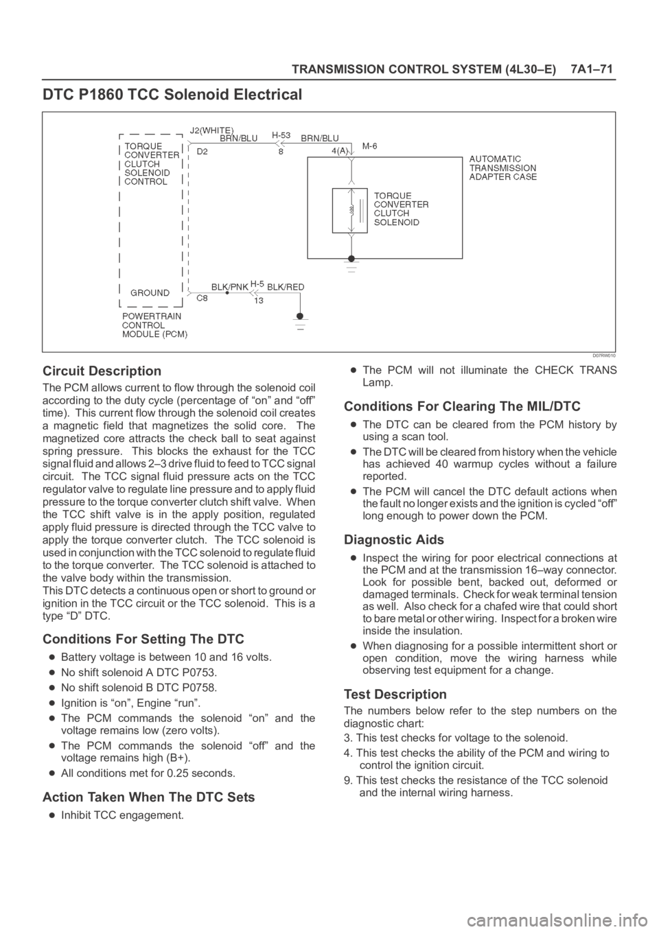
DTC P1860 TCC Solenoid Electrical
D07RW010
Circuit Description
The PCM allows current to flow through the solenoid coil
according to the duty cycle (percentage of “on” and “off”
time). This current flow through the solenoid coil creates
a magnetic field that magnetizes the solid core. The
magnetized core attracts the check ball to seat against
spring pressure. This blocks the exhaust for the TCC
signal fluid and allows 2–3 drive fluid to feed to TCC signal
circuit. The TCC signal fluid pressure acts on the TCC
regulator valve to regulate line pressure and to apply fluid
pressure to the torque converter clutch shift valve. When
the TCC shift valve is in the apply position, regulated
apply fluid pressure is directed through the TCC valve to
apply the torque converter clutch. The TCC solenoid is
used in conjunction with the TCC solenoid to regulate fluid
to the torque converter. The TCC solenoid is attached to
the valve body within the transmission.
This DTC detects a continuous open or short to ground or
ignition in the TCC circuit or the TCC solenoid. This is a
type “D” DTC.
Conditions For Setting The DTC
Battery voltage is between 10 and 16 volts.
No shift solenoid A DTC P0753.
No shift solenoid B DTC P0758.
Ignition is “on”, Engine “run”.
The PCM commands the solenoid “on” and the
voltage remains low (zero volts).
The PCM commands the solenoid “off” and the
voltage remains high (B+).
All conditions met for 0.25 seconds.
Action Taken When The DTC Sets
Inhibit TCC engagement.
The PCM will not illuminate the CHECK TRANS
Lamp.
Conditions For Clearing The MIL/DTC
The DTC can be cleared from the PCM history by
using a scan tool.
The DTC will be cleared from history when the vehicle
has achieved 40 warmup cycles without a failure
reported.
The PCM will cancel the DTC default actions when
the fault no longer exists and the ignition is cycled “off”
long enough to power down the PCM.
Diagnostic Aids
Inspect the wiring for poor electrical connections at
the PCM and at the transmission 16–way connector.
Look for possible bent, backed out, deformed or
damaged terminals. Check for weak terminal tension
as we ll. A lso ch eck fo r a ch af e d w ire th at cou l d s ho r t
to bare metal or other wiring. Inspect for a broken wire
inside the insulation.
When diagnosing for a possible intermittent short or
open condition, move the wiring harness while
observing test equipment for a change.
Test Description
The numbers below refer to the step numbers on the
diagnostic chart:
3. This test checks for voltage to the solenoid.
4. This test checks the ability of the PCM and wiring to
control the ignition circuit.
9. This test checks the resistance of the TCC solenoid
and the internal wiring harness.
Page 2517 of 6000
7C–8CLUTCH
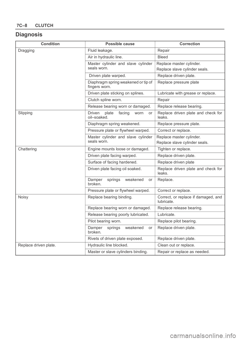
Diagnosis
ConditionPossible causeCorrection
DraggingFluid leakage.Repair
Air in hydraulic line.Bleed
Master cylinder and slave cylinder
seals worn. Replace master cylinder.
Replace slave cylinder seals.
Driven plate warped.Replace driven plate.
Diaphragm spring weakened or tip of
fingers worn. Replace pressure plate
Driven plate sticking on splines.Lubricate with grease or replace.
Clutch spline worn. Repair
Release bearing worn or damaged.Replace release bearing.
SlippingDriven plate facing worn or
oil–soaked.Replace driven plate and check for
leaks.
Diaphragm spring weakened.Replace pressure plate.
Pressure plate or flywheel warped.Correct or replace.
Master cylinder and slave cylinder
seals worn.Replace master cylinder.
Replace slave cylinder seals.
ChatteringEngine mounts loose or damaged.Tighten or replace.
Driven plate facing warped.Replace driven plate.
Surface of facing hardened.Replace driven plate
Driven plate facing oil soaked. Replace driven plate and check for
leaks.
Damper springs weakened or
broken. Replace.
Pressure plate or flywheel warped.Correct or replace.
NoisyReplace bearing binding.Correct, or replace if damaged, and
lubricate.
Replace bearing worn or damaged. Replace release bearing.
Release bearing poorly lubricated. Lubricate.
Pilot bearing worn.Replace pilot bearing.
Damper springs weakened or
broken.Replace driven plate.
Rivets of driven plate exposed.Replace driven plate.
Replace driven plate.Hydraulic line blocked.Clean out or replace.
Master or slave cylinders binding.Repair or replace as needed.