1998 OPEL FRONTERA crankshaft oil seal
[x] Cancel search: crankshaft oil sealPage 281 of 6000

1. Perform oil return operation.
2. Discharge and recover the refrigerant and remove
the compressor.
3. Drain the compressor oil and measure the extracted
oil.
4. Check the compressor oil for contamination.
5. Adjust the oil level as required.
6. Evacuate, charge and perform the oil return
operation.
7. Check the system operation.
Contamination of Compressor Oil
Unlike engine oil, no cleaning agent is added to the
compressor oil. Even if the compressor runs for a long
period of time (approximately one season), the oil never
becomes contaminated as long as there is nothing
wrong with the compressor or its method of use.
Inspect the extracted oil for any of the following
conditions:
The capacity of the oil has increased.
The oil has changed to red.
Foreign substances, metal powder, etc., are present
in the oil.
If any of these conditions exists, the compressor
oil is contaminated. Whenever contaminated
compressor oil is discovered, the receiver/drier
must be replaced.
Oil Return Operation
There is close affinity between the oil and the
refrigerant. During normal operation, part of the oil
recirculates with the refrigerant in the system. When
checking the amount of oil in the system, or replacing
any component of the system, the compressor must be
run in advance for oil return operation. The procedure
is as follows:
1. Open all the doors and the engine hood.
2. Start the engine and air conditioning switch to "ON"
and set the fan control knob at its highest position.
3. Run the compressor for more than 20 minutes
between 800 and 1,000 rpm in order to operate the
system.
4. Stop the engine.
Replacement of Component Parts
When replacing the system component parts, supply
the following amount of oil to the component parts to be
installed.
Compressor Leak Testing (External and
Internal)
Bench-Check Procedure
1. Install test plate J-39893 on rear head of compressor.
2. Using Refrigerant Recovery System, attach center
hose of manifold gage set on charging station to a
refrigerant drum standing in an upright drum.
3. Connect charging station high and low pressure
lines to corresponding fittings on test plate J-39893.
Suction port (low-side) of compressor has large
internal opening. Discharge port (high-side) has
smaller internal opening into compressor and
deeper recess.
4. Open low pressure control, high pressure control
and refrigerant control on charging station to allow
refrigerant vapor to flow into compressor.
5. Using a leak detector, check for leaks at pressure
relief valve, rear head switch location, compressor
front and rear head seals, center cylinder seal,
through bolt head gaskets and compressor shaft
seal. After checking, shut off low pressure control
and high-pressure control on charging station.
6. If an external leak is present, perform the necessary
corrective measures and recheck for leaks to make
certain the leak has been connected.
7. Recover the refrigerant.
8. Disconnect both hoses from the test plate J-39893.
9. Add 90 ml (3 oz.) new PAG lubricant to the
compressor assembly. Rotate the complete
compressor assembly (not the crankshaft or drive
plate hub) slowly several turns to distribute oil to all
cylinder and piston areas.
10. Install a M9
1.25 threaded nut on the compressor
crankshaft if the drive plate and clutch assembly are
not installed.
11. Using a box-end wrench or socket and handle,
rotate the compressor crankshaft or clutch drive
plate on the crankshaft several turns to insure
piston assembly to cylinder wall lubrication.
12. Using Refrigerant Recovery System, connect the
charging station high-pressure line to the test plate
J-39893 high-side connector.
13. Using Refrigerant Recovery System, connect the
charging station low-pressure line to the low
pressure port of the test plate J-39893. Oil will drain
out of the compressor suction port if the compressor
is positioned with the suction port downward. (Component parts to be (Amount of Oil)
installed)
Evaporator 50 cc (1.7 fl. oz.)
Condenser 30 cc (1.0 fl. oz.)
Receiver/dryer 30 cc (1.0 fl. oz.)
Refrigerant line (one 10 cc (0.3 fl. oz.)
piece)
(Amount of oil drained (Charging amount of oil
from used compressor) to new compressor)
more than 90 cc same as drained amount
(3.0 fl.oz)
less than 90 cc (3.0 fl.oz) 90 cc (3.0 fl.oz)
Page 957 of 6000
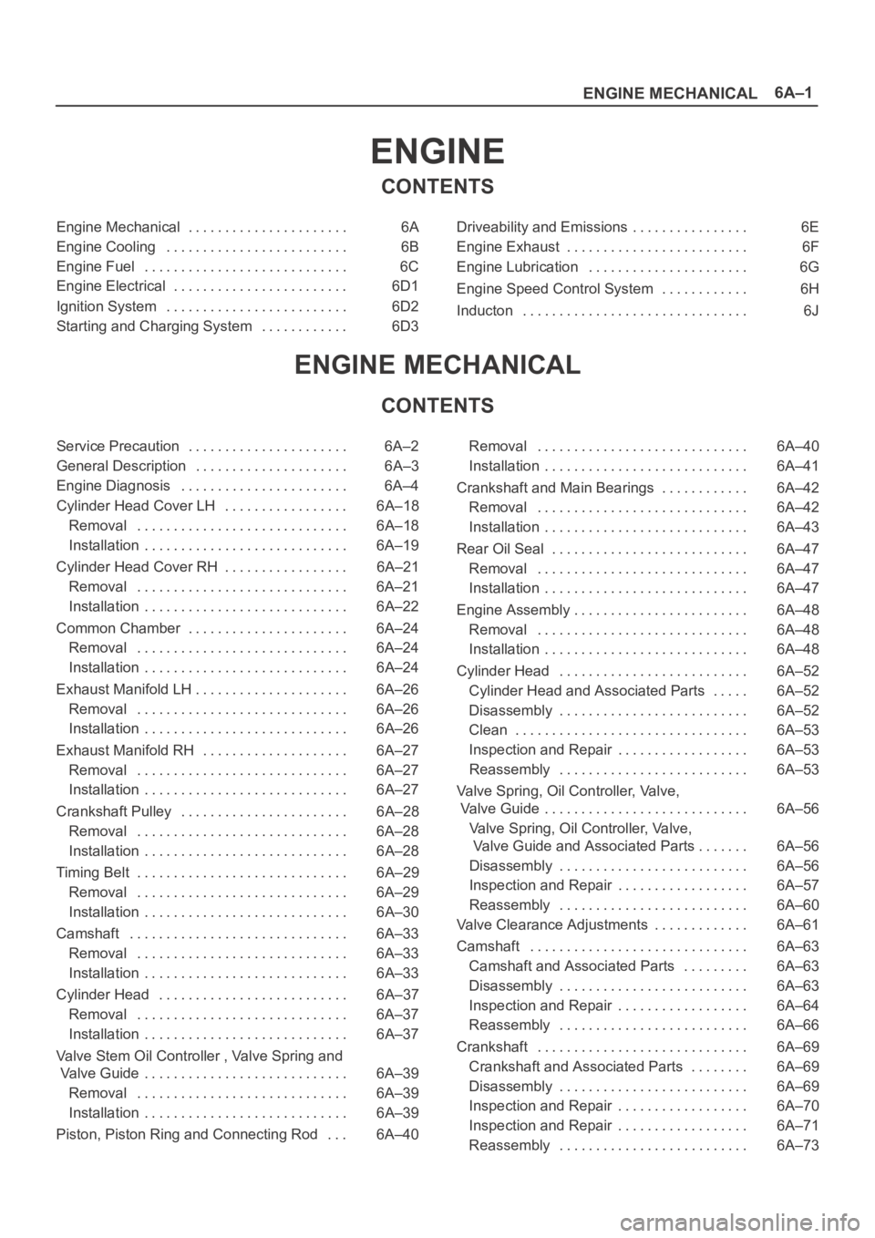
6A–1
ENGINE MECHANICAL
ENGINE
CONTENTS
Engine Mechanical 6A. . . . . . . . . . . . . . . . . . . . . .
Engine Cooling 6B. . . . . . . . . . . . . . . . . . . . . . . . .
Engine Fuel 6C. . . . . . . . . . . . . . . . . . . . . . . . . . . .
Engine Electrical 6D1. . . . . . . . . . . . . . . . . . . . . . . .
Ignition System 6D2. . . . . . . . . . . . . . . . . . . . . . . . .
Starting and Charging System 6D3. . . . . . . . . . . . Driveability and Emissions 6E. . . . . . . . . . . . . . . .
Engine Exhaust 6F. . . . . . . . . . . . . . . . . . . . . . . . .
Engine Lubrication 6G. . . . . . . . . . . . . . . . . . . . . .
Engine Speed Control System 6H. . . . . . . . . . . .
Inducton 6J. . . . . . . . . . . . . . . . . . . . . . . . . . . . . . .
ENGINE MECHANICAL
CONTENTS
Service Precaution 6A–2. . . . . . . . . . . . . . . . . . . . . .
General Description 6A–3. . . . . . . . . . . . . . . . . . . . .
Engine Diagnosis 6A–4. . . . . . . . . . . . . . . . . . . . . . .
Cylinder Head Cover LH 6A–18. . . . . . . . . . . . . . . . .
Removal 6A–18. . . . . . . . . . . . . . . . . . . . . . . . . . . . .
Installation 6A–19. . . . . . . . . . . . . . . . . . . . . . . . . . . .
Cylinder Head Cover RH 6A–21. . . . . . . . . . . . . . . . .
Removal 6A–21. . . . . . . . . . . . . . . . . . . . . . . . . . . . .
Installation 6A–22. . . . . . . . . . . . . . . . . . . . . . . . . . . .
Common Chamber 6A–24. . . . . . . . . . . . . . . . . . . . . .
Removal 6A–24. . . . . . . . . . . . . . . . . . . . . . . . . . . . .
Installation 6A–24. . . . . . . . . . . . . . . . . . . . . . . . . . . .
Exhaust Manifold LH 6A–26. . . . . . . . . . . . . . . . . . . . .
Removal 6A–26. . . . . . . . . . . . . . . . . . . . . . . . . . . . .
Installation 6A–26. . . . . . . . . . . . . . . . . . . . . . . . . . . .
Exhaust Manifold RH 6A–27. . . . . . . . . . . . . . . . . . . .
Removal 6A–27. . . . . . . . . . . . . . . . . . . . . . . . . . . . .
Installation 6A–27. . . . . . . . . . . . . . . . . . . . . . . . . . . .
Crankshaft Pulley 6A–28. . . . . . . . . . . . . . . . . . . . . . .
Removal 6A–28. . . . . . . . . . . . . . . . . . . . . . . . . . . . .
Installation 6A–28. . . . . . . . . . . . . . . . . . . . . . . . . . . .
Timing Belt 6A–29. . . . . . . . . . . . . . . . . . . . . . . . . . . . .
Removal 6A–29. . . . . . . . . . . . . . . . . . . . . . . . . . . . .
Installation 6A–30. . . . . . . . . . . . . . . . . . . . . . . . . . . .
Camshaft 6A–33. . . . . . . . . . . . . . . . . . . . . . . . . . . . . .
Removal 6A–33. . . . . . . . . . . . . . . . . . . . . . . . . . . . .
Installation 6A–33. . . . . . . . . . . . . . . . . . . . . . . . . . . .
Cylinder Head 6A–37. . . . . . . . . . . . . . . . . . . . . . . . . .
Removal 6A–37. . . . . . . . . . . . . . . . . . . . . . . . . . . . .
Installation 6A–37. . . . . . . . . . . . . . . . . . . . . . . . . . . .
Valve Stem Oil Controller , Valve Spring and
Valve Guide 6A–39. . . . . . . . . . . . . . . . . . . . . . . . . . . .
Removal 6A–39. . . . . . . . . . . . . . . . . . . . . . . . . . . . .
Installation 6A–39. . . . . . . . . . . . . . . . . . . . . . . . . . . .
Piston, Piston Ring and Connecting Rod 6A–40. . . Removal 6A–40. . . . . . . . . . . . . . . . . . . . . . . . . . . . .
Installation 6A–41. . . . . . . . . . . . . . . . . . . . . . . . . . . .
Crankshaft and Main Bearings 6A–42. . . . . . . . . . . .
Removal 6A–42. . . . . . . . . . . . . . . . . . . . . . . . . . . . .
Installation 6A–43. . . . . . . . . . . . . . . . . . . . . . . . . . . .
Rear Oil Seal 6A–47. . . . . . . . . . . . . . . . . . . . . . . . . . .
Removal 6A–47. . . . . . . . . . . . . . . . . . . . . . . . . . . . .
Installation 6A–47. . . . . . . . . . . . . . . . . . . . . . . . . . . .
Engine Assembly 6A–48. . . . . . . . . . . . . . . . . . . . . . . .
Removal 6A–48. . . . . . . . . . . . . . . . . . . . . . . . . . . . .
Installation 6A–48. . . . . . . . . . . . . . . . . . . . . . . . . . . .
Cylinder Head 6A–52. . . . . . . . . . . . . . . . . . . . . . . . . .
Cylinder Head and Associated Parts 6A–52. . . . .
Disassembly 6A–52. . . . . . . . . . . . . . . . . . . . . . . . . .
Clean 6A–53. . . . . . . . . . . . . . . . . . . . . . . . . . . . . . . .
Inspection and Repair 6A–53
. . . . . . . . . . . . . . . . . .
Reassembly 6A–53. . . . . . . . . . . . . . . . . . . . . . . . . .
Valve Spring, Oil Controller, Valve,
Valve Guide 6A–56. . . . . . . . . . . . . . . . . . . . . . . . . . . .
Valve Spring, Oil Controller, Valve,
Valve Guide and Associated Parts 6A–56. . . . . . .
Disassembly 6A–56. . . . . . . . . . . . . . . . . . . . . . . . . .
Inspection and Repair 6A–57. . . . . . . . . . . . . . . . . .
Reassembly 6A–60. . . . . . . . . . . . . . . . . . . . . . . . . .
Valve Clearance Adjustments 6A–61. . . . . . . . . . . . .
Camshaft 6A–63. . . . . . . . . . . . . . . . . . . . . . . . . . . . . .
Camshaft and Associated Parts 6A–63. . . . . . . . .
Disassembly 6A–63. . . . . . . . . . . . . . . . . . . . . . . . . .
Inspection and Repair 6A–64. . . . . . . . . . . . . . . . . .
Reassembly 6A–66. . . . . . . . . . . . . . . . . . . . . . . . . .
Crankshaft 6A–69. . . . . . . . . . . . . . . . . . . . . . . . . . . . .
Crankshaft and Associated Parts 6A–69. . . . . . . .
Disassembly 6A–69. . . . . . . . . . . . . . . . . . . . . . . . . .
Inspection and Repair 6A–70. . . . . . . . . . . . . . . . . .
Inspection and Repair 6A–71. . . . . . . . . . . . . . . . . .
Reassembly 6A–73. . . . . . . . . . . . . . . . . . . . . . . . . .
Page 970 of 6000

6A–14
ENGINE MECHANICAL
Condition CorrectionPossible cause
Trouble in emission control systemHeated Oxygen Sensor circuit openCorrect or replace
Heated Oxygen Sensor defectiveReplace
Signal vacuum hose loosely fitted or
defectiveCorrect or replace
EGR Valve circuit open or shortedCorrect or replace
Exhaust Gas Recirculation Valve
defectiveReplace
ECT Sensor circuit open or shortedCorrect or replace
Canister Purge Valve circuit open or
shortedCorrect or replace
Canister Purge Valve defectiveReplace
ECT Sensor defectiveReplace
Positive Crankcase Ventilation
(PCV) valve and hose cloggedCorrect or replace
Evaporator systemRefer to Section 6E
Trouble in ignition system————Refer to “Engine Lacks Power”
Trouble in cylinder head partsCarbon deposits in combustion
chamberRemove carbon
Carbon deposit on valve, valve seat
and valve guideRemove carbon
Engine Oil Consumption Excessive
ConditionPossible causeCorrection
Oil leakingOil pan drain plug looseRetighten or replace gasket
Crankcase fixing bolts loosenedRetighten
Oil pan setting bolts loosenedRetighten
Oil pan gasket brokenReplace gasket
Front cover retaining bolts loose or
gasket brokenRetighten or replace gasket
Head cover fixing bolts loose or
gasket brokenRetighten or replace gasket
Oil cooler adapter crackedReplace
Oil cooler center bolt looseRetighten
Oil cooler O–ring brokenReplace
Oil cooler piping loose or brokenRetighten or replace
Oil filter adapter crackedReplace
Oil filter attaching bolt loose or rubber
gasket brokenRetighten or replace oil filter
Oil cooler brokenReplace
Crankshaft front or rear oil seal
defectiveReplace oil seal
Oil pressure unit loose or brokenRetighten or replace
Blow–by gas hose brokenReplace hose
Positive Crankcase Ventilation Valve
cloggedClean
Engine/Transmission coupling failedReplace oil seal
Page 975 of 6000

6A–19
ENGINE MECHANICAL
Legend
(1) Crankshaft Pulley
(2) Generator
(3) Auto Tensioner
(4) Idle Pulley
(5) Cooling Fan Pulley
(6) Power Steering Oil Pump
(7) Drive Belt
(8) Air Conditioner Compressor
12. Remove power steering oil pump pulley.
13. Remove fan pulley and bracket assembly.
14. Remove idle pulley assembly.
15. Remove auto tensioner assembly.
16. Remove crankshaft pulley using 5–8840–0133–0
crankshaft holder.
17. Remove timing belt covers from the right bank side to
the left bank side in order.
18. Remove ignition coil assemblies for the left side bank.
060RW018
Legend
(1) Ignition Coil Connectors
(2) Bolts
(3) Ignition Coil Assemblies
19. Remove cylinder head cover assembly.
Installation
1. Install cylinder head cover.
Clean the sealing surface of cylinder head and
cylinder head cover to remove oil and sealing
materials completely.
Apply sealant (TB-1207B or equivalent) of bead
diameter 2-3 mm at eight place of arched area of
camshaft bracket on front and rear sides.
The cylinder head cover must be installed within 5
minutes after sealant application to prevent
premature hardening of sealant.
014RW144
Tighten bolts to the specified torque.
Torque : 9 Nꞏm (0.9 Kgꞏm/78 lb in)
010RW008
2. Install ignition coil assemblies and tighten the fixing
bolts to the specified torque.
Torque : 4 Nꞏm (0.4 Kgꞏm/35 lb in)
3. Install timing belt covers from left bank side to right
bank side, and tighten the fixing bolts and nut to the
specified torque.
Torque : 19 Nꞏm (1.9 Kgꞏm/14 lb ft)
4. Install crankshaft pulley and tighten the fixing bolt
using 5–8840–0133–0 crankshaft holder to the
specified torque.
Torque : 167 Nꞏm (17.0 Kgꞏm/123 lb ft)
Page 978 of 6000

6A–22
ENGINE MECHANICAL
16. Remove timing belt covers for right bank side.
17. Reomve timing belt covers for right bank side.
060RW001
Legend
(1) Ignition Coil Connectors
(2) Bolts
(3) Ignition Coil Assemblies
18. Remove ignition coil assemblies for the right side
bank.
19. Remove cylinder head cover assembly.
Installation
1. Install cylinder head cover.
Clean the sealing surface of cylinder head and
cylinder head cover to remove oil and sealing
materials completely.
Apply sealant (TB-1207B or equivalent) of bead
diameter 2-3 mm at eight place of arched area of
camshaft bracket on front and rear sides.
The cylinder head cover must be installed within 5
minutes after sealant application before the sealant
hardens.
014RW143
Tighten bolts in turn to the specified torque.
Torque : 8.8 Nꞏm (0.9 Kgꞏm/78 lb in)
010RW007
2. Install ignition coil assemblies and tighten the fixing
bolts to the specified torque.
Torque : 4 Nꞏm (0.4 Kgꞏm/35 lb in)
3. Install timing belt cover and tighten the fixing bolts and
nut to the specified torque.
Torque : 19 Nꞏm (1.9 Kgꞏm/14 lb ft)
4. Install crankshaft pulley and tighten the fixing bolt
using 5–8840–0133–0 crankshaft holder to the
specified torque.
Torque : 167 Nꞏm (17 Kgꞏm/123 lb ft)
5. Install auto tensioner assembly and tighten the fixing
bolts to the specified torque.
Torque :
Shorter Bolt : 20 Nꞏm (2.0 Kgꞏm/14.8 lb ft)
Longer Bolt : 39 Nꞏm (4.0 Kgꞏm/28.8 lb ft)
Page 988 of 6000

6A–32
ENGINE MECHANICAL
Legend
(1) Up Side
(2) Down Side
(3) Direction for Installation
(4) Locking Pin
3. Remove double clips or equivalent clips, from
timing belt pulleys.
Turn the crankshaft pulley clockwise by two turns.
3. Install timing belt cover.
Remove crankshaft pulley that was installed in step
1 item 5.
Tighten bolts to the specified torque.
Torque: 19 Nꞏm (1.9 Kgꞏm/14 lb ft)
020RW004
Legend
(1) Timing Belt Cover RH
(2) Timing Belt Cover LH
(3) Timing Belt Cover Lower
020RW003
Legend
(1) Timing Belt Cover
(2) Rubber Bushing
(3) Sealing Rubber
(4) Cylinder Body
4. Install crankshaft pulley using 5–8840–0133–0, hold
the crankshaft pulley and tighten center bolt to the
specified torque.
Torque : 167 Nꞏm (17.0 Kgꞏm/123 lb ft)
5. Install fan pulley bracket and tighten fixing bolts to the
specified torque.
Torque : 22 Nꞏm (2.2 Kgꞏm/16 lb ft)
6. Install power steering pump assembly and tighten to
the specified torque.
To r q u e :
M8 bolt : 22 Nꞏm (2.2 Kgꞏm/16 lb ft)
M10 bolt : 46 Nꞏm (4.7 Kgꞏm/34 lb ft)
7. Install cooling fan assembly and tighten bolts/nuts to
the specified torque.
Torque : 22 Nꞏm (2.2 Kgꞏm/16 lb ft) for fan pulley
and fan bracket.
Torque : 10 Nꞏm (1.0 Kgꞏm/88.5 lb in) for fan and
clutch assembly.
8. Move drive belt tensioner to loose side using wrench,
then install drive belt to normal position.
850RW001
Legend
(1) Crankshaft Pulley
(2) Cooling Fan Pulley
(3) Auto Tensioner
(4) Generator
(5) Air Conditioner Compressor
(6) Power Steering Oil Pump
(7) Idle Pulley
(8) Drive Belt
9. Install radiator upper fan shroud.
10. Install air cleaner assembly.
Page 998 of 6000

6A–42
ENGINE MECHANICAL
Crankshaft and Main Bearings
Removal
F06RW010
Legend
(1) Engine Assembly
(2) Crankshaft Pulley
(3) Timing Belt Cover
(4) Timing Belt
(5) Crankcase with Oil Pan
(6) Oil Pipe
(7) Oil Strainer(8) Oil Pump Assembly
(9) Cylinder Body Side Bolt
(10) Oil Gallery
(11) Flywheel
(12) Rear Oil Seal Retainer
(13) Connecting Rod Cap
(14) Crankshaft Main Bearing Cap
(15) Crankshaft and Main Bearing
1. Remove engine assembly.
Refer to removal procedure for Engine Assembly in
this manual.
2. Remove timing belt.
Refer to removal procedure for Timing Belt in this
manual.3. Remove oil pan and crankcase.
Refer to removal procedure for Oil Pan and
Crankcase in this manual.
4. Remove oil pipe with O-ring.
5. Remove oil strainer assembly with O-ring.
Page 999 of 6000

6A–43
ENGINE MECHANICAL
6. Remove oil pump assembly.
Refer to removal procedure for Oil Pump in this
manual.
7. Remove cylinder body side bolts.
8. Remove oil gallery.
9. Remove flywheel.
10. Remove rear oil seal retainer.
Refer to removal procedure for Rear Oil Seal in this
manual.
11. Remove connecting rod caps.
12. Remove crankshaft main bearing caps.
13. Remove crankshaft and main bearings.
Installation
1. Install crankshaft and main bearings.
Install main bearing in the cylinder block and main
bearing cap respectively.
Apply new engine oil to upper and lower main
bearings.
NOTE:
Do not apply engine oil to the bearing back faces.
Make sure that main bearings are in correct position.
Install crankshaft with care.
Apply engine oil to the thrust washer.
Install thrust washer on No.3 journal.
Oil grooves in thrust washer must face the
crankshaft.
015RS012
015RS013
2. Install crankshaft main bearing caps.
Apply engine oil to the thread and seating surface of
each bearing cap fixing bolt.
NOTE:
Do not apply engine oil to the bearing back faces.
Install bearing caps in the order of numbers, starting
with cylinder block front side.
Tighten main bearing fixing bolts to the specified
torque.
Torque : 39 Nꞏm (4.0 Kgꞏm/29 lb ft)
After tightening the bolts, make sure that the
crankshaft rotates smoothly.
3. Install connecting rod caps.
The cap number must be same as connecting rod
number.
Apply engine oil to the thread and seating surface of
each nut.
Tighten nuts to the specified torque.
Torque : 54 Nꞏm (5.5 Kgꞏm/40 lb ft)
After tightening the nuts, make sure that the
crankshaft rotates smoothly.
4. Install rear oil seal retainer.
Remove oil on cylinder block and retainer fitting
surface.
Apply sealant (TB1207B or equivalent) to retainer
fitting surface as shown in illustration.