1998 OPEL FRONTERA refri
[x] Cancel search: refriPage 278 of 6000
COMPRESSOR SHAFT SEAL
Service Precaution
When replacing the shaft seal assembly, pressure relief
valve or control switches, it will be necessary to recover
the refrigerant. Other than clutch repair procedures, the
same holds true for any disassembly of the compressor.
A clean workbench covered with a sheet of clean
paper, and a place (clean trays, etc) for all parts being
removed and replaced is important, as is the use of
proper clean service tools.
CAUTION: Any attempt to use makeshift or
inadequate service tools or equipment may result
in damage and/or improper compressor operation.
All parts required for servicing the internal compressor
are protected by a preservative process and packaged
in a manner which will eliminate the necessity of
cleaning, washing or flushing of the parts. The parts
can be used in the internal assembly just as they are
removed from the service package. Seals and
protective packaging should be left intact until just
prior to installation.
If the compressor rear head, front head or cylinder and
shaft assembly is to be serviced or replaced, the oil in
the compressor must be drained, measured, recorded
and replaced.
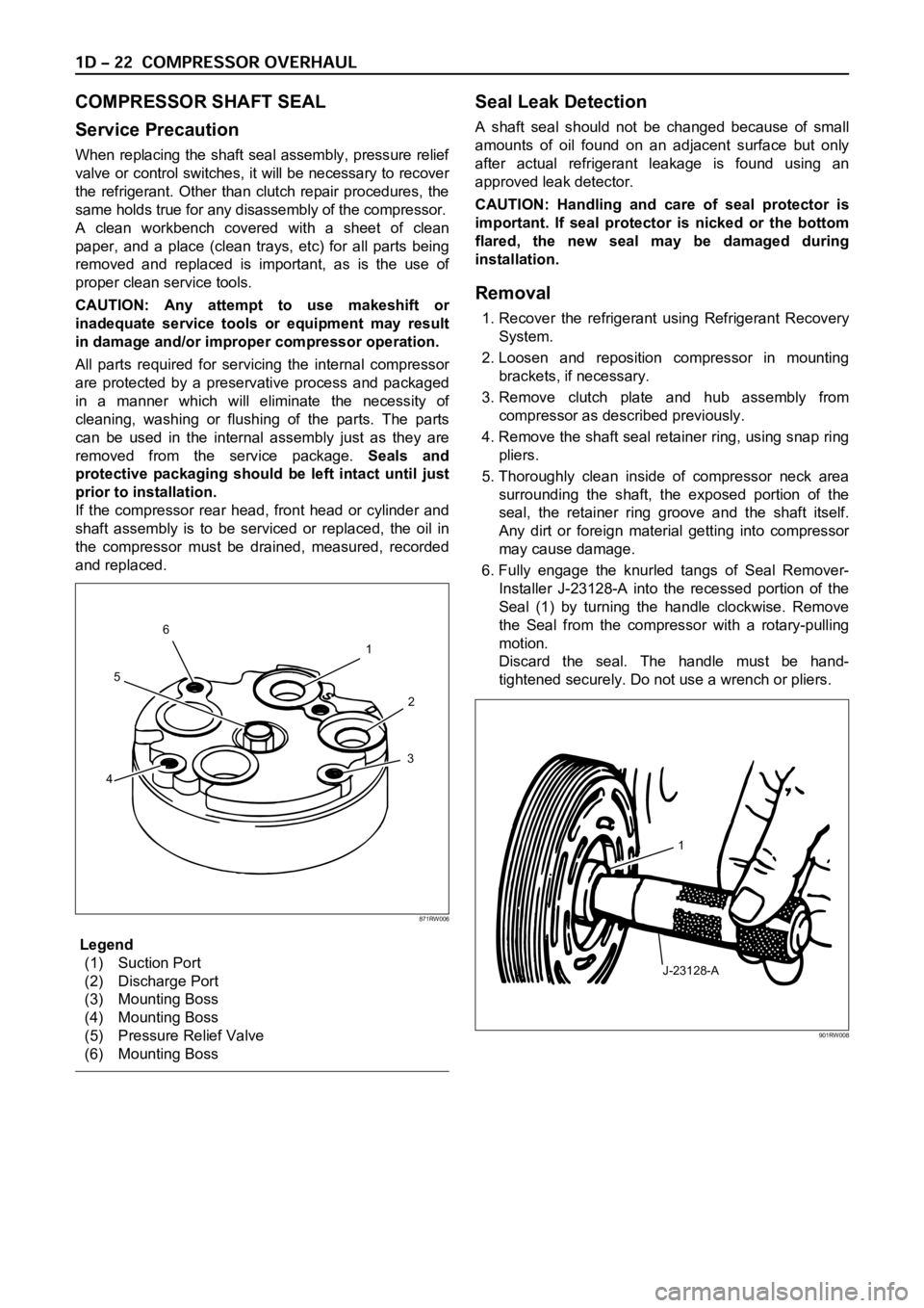
Legend
(1) Suction Port
(2) Discharge Port
(3) Mounting Boss
(4) Mounting Boss
(5) Pressure Relief Valve
(6) Mounting Boss
Seal Leak Detection
A shaft seal should not be changed because of small
amounts of oil found on an adjacent surface but only
after actual refrigerant leakage is found using an
approved leak detector.
CAUTION: Handling and care of seal protector is
important. If seal protector is nicked or the bottom
flared, the new seal may be damaged during
installation.
Removal
1. Recover the refrigerant using Refrigerant Recovery
System.
2. Loosen and reposition compressor in mounting
brackets, if necessary.
3. Remove clutch plate and hub assembly from
compressor as described previously.
4. Remove the shaft seal retainer ring, using snap ring
pliers.
5. Thoroughly clean inside of compressor neck area
surrounding the shaft, the exposed portion of the
seal, the retainer ring groove and the shaft itself.
Any dirt or foreign material getting into compressor
may cause damage.
6. Fully engage the knurled tangs of Seal Remover-
Installer J-23128-A into the recessed portion of the
Seal (1) by turning the handle clockwise. Remove
the Seal from the compressor with a rotary-pulling
motion.
Discard the seal. The handle must be hand-
tightened securely. Do not use a wrench or pliers.
1
2
3
456
871RW006
J-23128-A1
901RW008
Page 279 of 6000
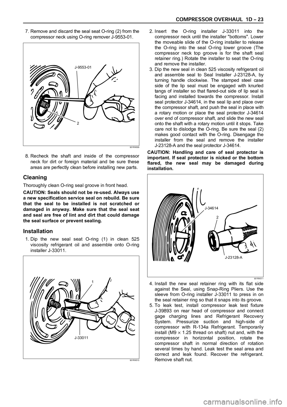
7. Remove and discard the seal seat O-ring (2) from the
compressor neck using O-ring remover J-9553-01.
8. Recheck the shaft and inside of the compressor
neck for dirt or foreign material and be sure these
areas are perfectly clean before installing new parts.
Cleaning
Thoroughly clean O-ring seal groove in front head.
CAUTION: Seals should not be re-used. Always use
a new specification service seal on rebuild. Be sure
that the seal to be installed is not scratched or
damaged in anyway. Make sure that the seal seat
and seal are free of lint and dirt that could damage
the seal surface or prevent sealing.
Installation
1. Dip the new seal seat O-ring (1) in clean 525
viscosity refrigerant oil and assemble onto O-ring
installer J-33011.2. Insert the O-ring installer J-33011 into the
compressor neck until the installer "bottoms". Lower
the moveable slide of the O-ring installer to release
the O-ring into the seal O-ring lower groove (The
compressor neck top groove is for the shaft seal
retainer ring.) Rotate the installer to seat the O-ring
and remove the installer.
3. Dip the new seal in clean 525 viscosity refrigerant oil
and assemble seal to Seal Installer J-23128-A, by
turning handle clockwise. The stamped steel case
side of the lip seal must be engaged with knurled
tangs of installer so that flared-out side of lip seal is
facing and installed towards the compressor. Install
seal protector J-34614, in the seal lip and place over
the compressor shaft, and push the seal in place with
a rotary motion or place the seal protector J-34614
over end of compressor shaft, and slide the new seal
onto the shaft with a rotary motion until it stops. Take
care not to dislodge the O-ring. Be sure the seal (2)
makes good contact with the O-ring. Disengage the
installer from the seal and remove the installer
J-23128-A and the seal protector J-34614.
CAUTION: Handling and care of seal protector is
important. If seal protector is nicked or the bottom
flared, the new seal may be damaged during
installation.
4. Install the new seal retainer ring with its flat side
against the Seal, using Snap-Ring Pliers. Use the
sleeve from O-ring installer J-33011 to press in on
the seal retainer ring so that it snaps into its groove.
5. To leak test, install compressor leak test fixture
J-39893 on rear head of compressor and connect
gage charging lines and Refrigerant Recovery
System. Pressurize suction and high-side of
compressor with R-134a Refrigerant. Temporarily
install (M9
1.25 thread on shaft) nut and, with the
compressor in horizontal position, rotate the
compressor shaft in normal direction of rotation
several times by hand. Leak test the seal area and
correct and leak found. Recover the refrigerant.
Remove shaft nut.
2 J-9553-01
901RW009
1
J-33011
901RW010
J-34614
2
J-23128-A
901RW011
Page 280 of 6000

6. Remove any excess oil resulting from installing the
new seal parts from the shaft and inside the
compressor neck.
7. Install the clutch plate and hub assembly as
described previously.8. Reinstall compressor belt and tighten bracket.
9. Evacuate and charge the refrigerant system.
COMPRESSOR PRESSURE RELIEF VALVE
Removal
1. Recover the refrigerant using Refrigerant Recovery
System.
2. Remove old pressure relief valve.
Installation
1. Clean valve seat area on rear head.2. Lubricate O-ring of new pressure relief valve and
O-ring assembly with new 525 viscosity refrigerant
oil. Install new valve and torque in place, 9.0 Nꞏm
(6.1 ft lbs)
3. Evacuate and recharge the system.
4. Leak test system.
COMPRESSOR OIL
Compressor Oil Check
The oil used to lubricate the compressor is circulating
with the refrigerant.
Whenever replacing any component of the system or a
large amount of gas leakage occurs, add oil to maintain
the original amount of oil.
Checking and Adjusting Oil Quantity for
Used Compressor
1. Perform oil return operation. Refer to Oil Return
Operation in this section.
2. Discharge and recover refrigerant and remove the
compressor.
3. Drain the compressor oil and measure the extracted
oil with a measuring cylinder.
4. If the amount of oil drained is much less than 90 cc
(3.0 fl. oz.), some refrigerant may have leaked out.
Conduct a leak tests on the connections of each
system, and if necessary, repair or replace faulty
parts.
5. Check the compressor oil contamination. (Refer to
Contamination of Compressor Oil in this section.)
6. Adjust the oil level following the next procedure
below.7. Install the compressor, then evacuate, charge and
perform the oil return operation.
8. Check system operation.
When it is impossible to preform oil return
operation, the compressor oil should be checked in
the following order:
1. Discharge and recover refrigerant and remove the
compressor.
2. Drain the compressor oil and measure the extracted
oil with a measuring cylinder.
3. Check the oil for contamination.
4. If more than 90 cc (3.0 fl. oz.) of oil is extracted from
the compressor, supply the same amount of oil to
the compressor to be installed. If the amount of oil
extracted is less than 90 cc (3.0 fl. oz.), recheck the
compressor oil in the following order:
5. Supply 90 cc (3.0 fl. oz.) of oil to the compressor
and install it onto the vehicle.
6. Evacuate and recharge with the proper amount of
refrigerant.
7. Perform the oil return operation.
8. Remove the compressor and recheck the amount of
oil.
9. Adjust the compressor oil, if necessary.
Checking and Adjusting for Compressor
Replacement
The oil is not charged in compressor (service parts). So
it is necessary to charge the proper amount of oil to the
new compressor. (Oil Capacity)
Capacity total in system 150 cc (5.0 fl.oz)
Compressor (Service 150 cc (5.0 fl.oz)
parts) charging amount
(Collected Amount) (Charging Amount)
more than 90 cc same as collected
(3.0 fl.oz) amount
less than 90 cc (3.0 fl.oz) 90 cc (3.0 fl.oz)
(Collected Amount) (Charging Amount)
more than 90 cc same as collected
(3.0 fl.oz) amount
less than 90 cc (3.0 fl.oz) 90 cc (3.0 fl.oz)
Page 281 of 6000

1. Perform oil return operation.
2. Discharge and recover the refrigerant and remove
the compressor.
3. Drain the compressor oil and measure the extracted
oil.
4. Check the compressor oil for contamination.
5. Adjust the oil level as required.
6. Evacuate, charge and perform the oil return
operation.
7. Check the system operation.
Contamination of Compressor Oil
Unlike engine oil, no cleaning agent is added to the
compressor oil. Even if the compressor runs for a long
period of time (approximately one season), the oil never
becomes contaminated as long as there is nothing
wrong with the compressor or its method of use.
Inspect the extracted oil for any of the following
conditions:
The capacity of the oil has increased.
The oil has changed to red.
Foreign substances, metal powder, etc., are present
in the oil.
If any of these conditions exists, the compressor
oil is contaminated. Whenever contaminated
compressor oil is discovered, the receiver/drier
must be replaced.
Oil Return Operation
There is close affinity between the oil and the
refrigerant. During normal operation, part of the oil
recirculates with the refrigerant in the system. When
checking the amount of oil in the system, or replacing
any component of the system, the compressor must be
run in advance for oil return operation. The procedure
is as follows:
1. Open all the doors and the engine hood.
2. Start the engine and air conditioning switch to "ON"
and set the fan control knob at its highest position.
3. Run the compressor for more than 20 minutes
between 800 and 1,000 rpm in order to operate the
system.
4. Stop the engine.
Replacement of Component Parts
When replacing the system component parts, supply
the following amount of oil to the component parts to be
installed.
Compressor Leak Testing (External and
Internal)
Bench-Check Procedure
1. Install test plate J-39893 on rear head of compressor.
2. Using Refrigerant Recovery System, attach center
hose of manifold gage set on charging station to a
refrigerant drum standing in an upright drum.
3. Connect charging station high and low pressure
lines to corresponding fittings on test plate J-39893.
Suction port (low-side) of compressor has large
internal opening. Discharge port (high-side) has
smaller internal opening into compressor and
deeper recess.
4. Open low pressure control, high pressure control
and refrigerant control on charging station to allow
refrigerant vapor to flow into compressor.
5. Using a leak detector, check for leaks at pressure
relief valve, rear head switch location, compressor
front and rear head seals, center cylinder seal,
through bolt head gaskets and compressor shaft
seal. After checking, shut off low pressure control
and high-pressure control on charging station.
6. If an external leak is present, perform the necessary
corrective measures and recheck for leaks to make
certain the leak has been connected.
7. Recover the refrigerant.
8. Disconnect both hoses from the test plate J-39893.
9. Add 90 ml (3 oz.) new PAG lubricant to the
compressor assembly. Rotate the complete
compressor assembly (not the crankshaft or drive
plate hub) slowly several turns to distribute oil to all
cylinder and piston areas.
10. Install a M9
1.25 threaded nut on the compressor
crankshaft if the drive plate and clutch assembly are
not installed.
11. Using a box-end wrench or socket and handle,
rotate the compressor crankshaft or clutch drive
plate on the crankshaft several turns to insure
piston assembly to cylinder wall lubrication.
12. Using Refrigerant Recovery System, connect the
charging station high-pressure line to the test plate
J-39893 high-side connector.
13. Using Refrigerant Recovery System, connect the
charging station low-pressure line to the low
pressure port of the test plate J-39893. Oil will drain
out of the compressor suction port if the compressor
is positioned with the suction port downward. (Component parts to be (Amount of Oil)
installed)
Evaporator 50 cc (1.7 fl. oz.)
Condenser 30 cc (1.0 fl. oz.)
Receiver/dryer 30 cc (1.0 fl. oz.)
Refrigerant line (one 10 cc (0.3 fl. oz.)
piece)
(Amount of oil drained (Charging amount of oil
from used compressor) to new compressor)
more than 90 cc same as drained amount
(3.0 fl.oz)
less than 90 cc (3.0 fl.oz) 90 cc (3.0 fl.oz)
Page 282 of 6000

14. Attach the compressor to the J-34992 holding
fixture and mount the compressor in a vise so that
the compressor will be in a horizontal position and
the shaft can be turned with a wrench.
15. Using a wrench, rotate the compressor crankshaft
or drive plate hub ten complete revolutions at a
speed of approximately one-revolution per second
turning the compressor at less than one-revolution
per second can result in a lower pump-up pressure
and disqualify a good pumping compressor.
16. Observe the reading on high-pressure gauge at the
completion of the tenth revolution of the
compressor. The pressure reading for a good
pumping compressor should be 690 kPa (100 psi)
or above. A pressure reading of less than 620 kPa
(90 psi) would indicate one or more suction and/or
discharge valves leaking an internal leak, or an
inoperative valve, and the refrigerant must be
recovered and the compressor disassembled and
checked for cause of leak. Repair as needed,
reassemble and repeat the pump-up test. Externally
leak test.
17. When the pressure pump-up test is completed,
recover the refrigerant from the high-side and
remove the test plate J-39893.
18. Tilt the compressor so that the compressor suction
and discharge ports are down. Drain the PAG
lubricant from the compressor.
19. Allow the compressor to drain for 10 minutes, then
refill with the proper amount of PAG lubricant, per
oil balance procedure described previously. The
PAG lubricant may be poured into the suction port.
If further assembly or processing is required, a
shipping plate or test plate J-39893 should be
installed to keep out air, dirt and moisture until the
compressor is installed.
Page 1171 of 6000
6E–54
ENGINE DRIVEABILITY AND EMISSIONS
A/C Clutch Control Circuit Diagnosis
D06RW085
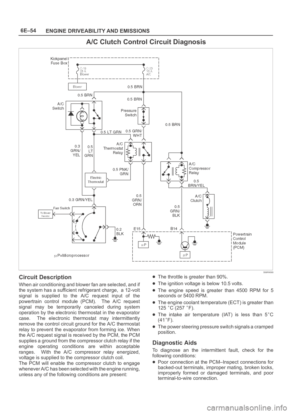
Circuit Description
When air conditioning and blower fan are selected, and if
the system has a sufficient refrigerant charge, a 12-volt
signal is supplied to the A/C request input of the
powertrain control module (PCM). The A/C request
signal may be temporarily canceled during system
operation by the electronic thermostat in the evaporator
case. The electronic thermostat may intermittently
remove the control circuit ground for the A/C thermostat
relay to prevent the evaporator from forming ice. When
the A/C request signal is received by the PCM, the PCM
supplies a ground from the compressor clutch relay if the
engine operating conditions are within acceptable
ranges. With the A/C compressor relay energized,
voltage is supplied to the compressor clutch coil.
The PCM will enable the compressor clutch to engage
whenever A/C has been selected with the engine running,
unless any of the following conditions are present:
The throttle is greater than 90%.
The ignition voltage is below 10.5 volts.
The engine speed is greater than 4500 RPM for 5
seconds or 5400 RPM.
The engine coolant temperature (ECT) is greater than
125
C (257 F).
The intake air temperature (IAT) is less than 5C
(41
F).
The power steering pressure switch signals a cramped
position.
Diagnostic Aids
To diagnose an the intermittent fault, check for the
following conditions:
Poor connection at the PCM–Inspect connections for
backed-out terminals, improper mating, broken locks,
improperly formed or damaged terminals, and poor
terminal-to-wire connection.
Page 1172 of 6000
6E–55 ENGINE DRIVEABILITY AND EMISSIONS
Damaged harness–Inspect the wiring harness for
damage. If the harness appears to OK, observe the
A/C clutch while moving connectors and wiring
harnesses related to the A/C. A sudden clutch
malfunction will indicate the source of the intermittent
fault.
A/C Clutch Diagnosis
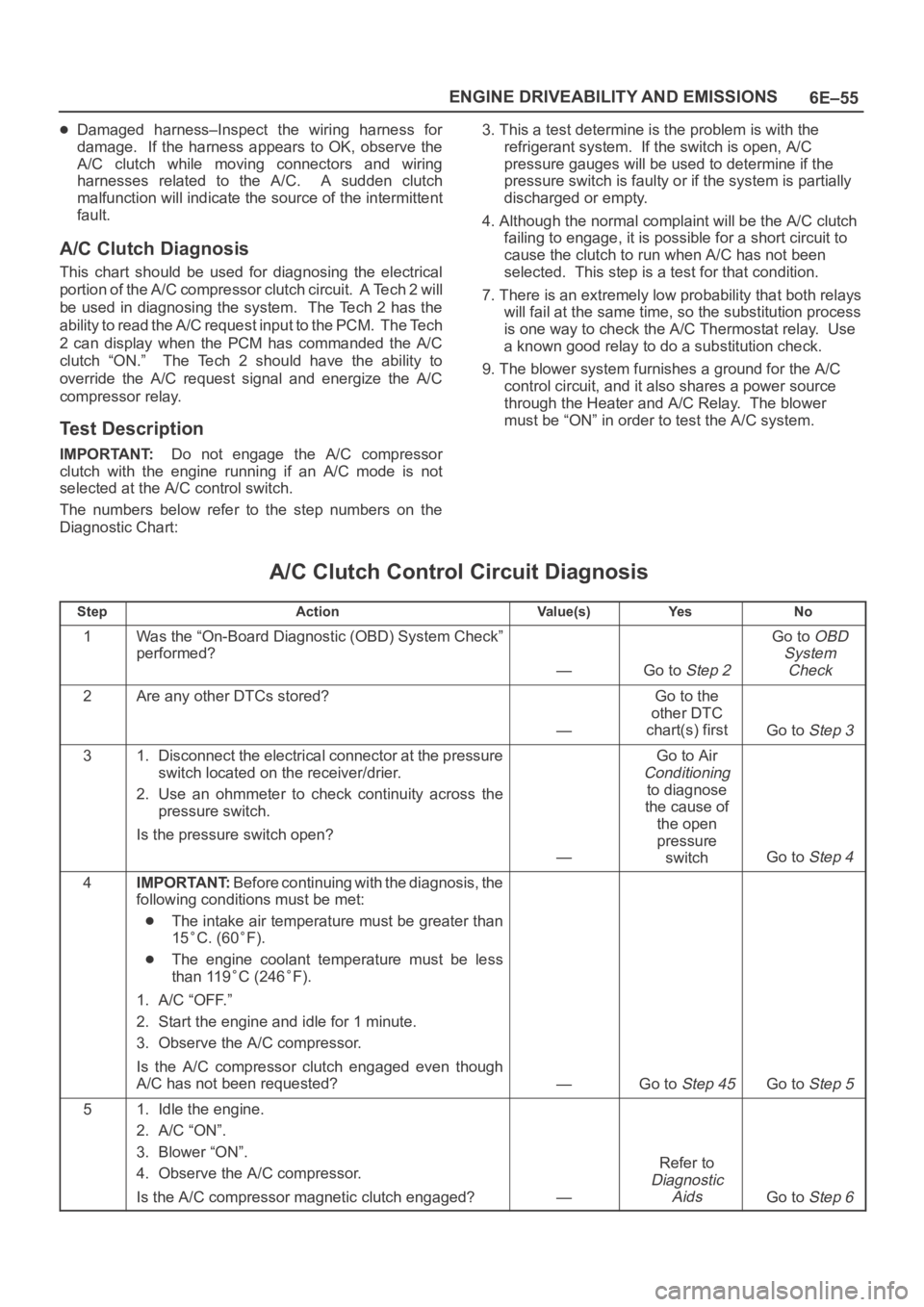
This chart should be used for diagnosing the electrical
p o r t i o n o f t h e A / C c o m p r e s s o r c l u t c h c i r c u i t . A Te c h 2 w i l l
be used in diagnosing the system. The Tech 2 has the
ability to read the A/C request input to the PCM. The Tech
2 can display when the PCM has commanded the A/C
clutch “ON.” The Tech 2 should have the ability to
override the A/C request signal and energize the A/C
compressor relay.
Test Description
IMPORTANT:Do not engage the A/C compressor
clutch with the engine running if an A/C mode is not
selected at the A/C control switch.
The numbers below refer to the step numbers on the
Diagnostic Chart:3. This a test determine is the problem is with the
refrigerant system. If the switch is open, A/C
pressure gauges will be used to determine if the
pressure switch is faulty or if the system is partially
discharged or empty.
4. Although the normal complaint will be the A/C clutch
failing to engage, it is possible for a short circuit to
cause the clutch to run when A/C has not been
selected. This step is a test for that condition.
7. There is an extremely low probability that both relays
will fail at the same time, so the substitution process
is one way to check the A/C Thermostat relay. Use
a known good relay to do a substitution check.
9. The blower system furnishes a ground for the A/C
control circuit, and it also shares a power source
through the Heater and A/C Relay. The blower
must be “ON” in order to test the A/C system.
A/C Clutch Control Circuit Diagnosis
StepActionVa l u e ( s )Ye sNo
1Was the “On-Board Diagnostic (OBD) System Check”
performed?
—Go to Step 2
Go to OBD
System
Check
2Are any other DTCs stored?
—
Go to the
other DTC
chart(s) first
Go to Step 3
31. Disconnect the electrical connector at the pressure
switch located on the receiver/drier.
2. Use an ohmmeter to check continuity across the
pressure switch.
Is the pressure switch open?
—
Go to Air
Conditioning
to diagnose
the cause of
the open
pressure
switch
Go to Step 4
4IMPORTANT:Before continuing with the diagnosis, the
following conditions must be met:
The intake air temperature must be greater than
15
C. (60F).
The engine coolant temperature must be less
than 119
C (246F).
1. A/C “OFF.”
2. Start the engine and idle for 1 minute.
3. Observe the A/C compressor.
Is the A/C compressor clutch engaged even though
A/C has not been requested?
—Go to Step 45Go to Step 5
51. Idle the engine.
2. A/C “ON”.
3. Blower “ON”.
4. Observe the A/C compressor.
Is the A/C compressor magnetic clutch engaged?
—
Refer to
Diagnostic
Aids
Go to Step 6
Page 1466 of 6000
6E–349 ENGINE DRIVEABILITY AND EMISSIONS
Damage during re-gapping can happen if the gapping
tool is pushed against the center electrode or the
insulator around it, causing the insulator to crack.
When re-gapping a spark plug, make the adjustment
by bending only the ground side terminal, keeping the
tool clear of other parts.
”Heat shock” breakage in the lower insulator tip
generally occurs during several engine operating
conditions (high speeds or heavy loading) and may be
caused by over-advanced timing or low grade fuels.
Heat shock refers to a rapid increase in the tip
temperature that causes the insulator material to
crack.
Spark plugs with less than the recommended amount of
service can sometimes be cleaned and re-gapped , then
returned to service. However, if there is any doubt about
the serviceability of a spark plug, replace it. Spark plugs
with cracked or broken insulators should always be
replaced.
A/C Clutch Diagnosis
A/C Clutch Circuit Operation
A 12-volt signal is supplied to the A/C request input of the
PCM when the A/C is selected through the A/C control
switch.
The A/C compressor clutch relay is controlled through the
PCM. This allows the PCM to modify the idle air control
position prior to the A/C clutch engagement for better idle
quality. If the engine operating conditions are within their
specified calibrated acceptable ranges, the PCM will
enable the A/C compressor relay. This is done by
providing a ground path for the A/C relay coil within the
PCM. When the A/C compressor relay is enabled,
battery voltage is supplied to the compressor clutch coil.
The PCM will enable the A/C compressor clutch
whenever the engine is running and the A/C has been
requested. The PCM will not enable the A/C compressor
clutch if any of the following conditions are met:
The throttle is greater than 90%.
The engine speed is greater than 6315 RPM.
The ECT is greater than 119C (246F).
The IAT is less than 5C (41F).
The throttle is more than 80% open.
A/C Clutch Circuit Purpose
The A/C compressor operation is controlled by the
powertrain control module (PCM) for the following
reasons:
It improvises idle quality during compressor clutch
engagement.
It improvises wide open throttle (WOT) performance.
It provides A/C compressor protection from operation
with incorrect refrigerant pressures.
The A/C electrical system consists of the following
components:
The A/C control head.
The A/C refrigerant pressure switches.
The A/C compressor clutch.
The A/C compressor clutch relay.
The PCM.
A/C Request Signal
This signal tells the PCM when the A/C mode is selected
at the A/C control head. The PCM uses this to adjust the
idle speed before turning on the A/C clutch. The A/C
compressor will be inoperative if this signal is not
available to the PCM.
Refer to
A/C Clutch Circuit Diagnosis for A/C wiring
diagrams and diagnosis for A/C electrical system.
General Description (Exhaust Gas
Recirculation (EGR) System)
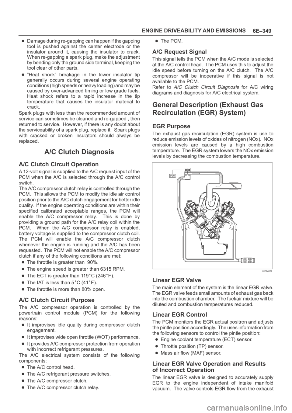
EGR Purpose
The exhaust gas recirculation (EGR) system is use to
reduce emission levels of oxides of nitrogen (NOx). NOx
emission levels are caused by a high combustion
temperature. The EGR system lowers the NOx emission
levels by decreasing the combustion temperature.
057RW002
Linear EGR Valve
The main element of the system is the linear EGR valve.
The EGR valve feeds small amounts of exhaust gas back
into the combustion chamber. The fuel/air mixture will be
diluted and combustion temperatures reduced.
Linear EGR Control
The PCM monitors the EGR actual positron and adjusts
the pintle position accordingly. The uses information from
the following sensors to control the pintle position:
Engine coolant temperature (ECT) sensor.
Throttle position (TP) sensor.
Mass air flow (MAF) sensor.
Linear EGR Valve Operation and Results
of Incorrect Operation
The linear EGR valve is designed to accurately supply
EGR to the engine independent of intake manifold
vacuum. The valve controls EGR flow from the exhaust