1998 OPEL FRONTERA low oil pressure
[x] Cancel search: low oil pressurePage 4506 of 6000
6A–10
ENGINE MECHANICAL
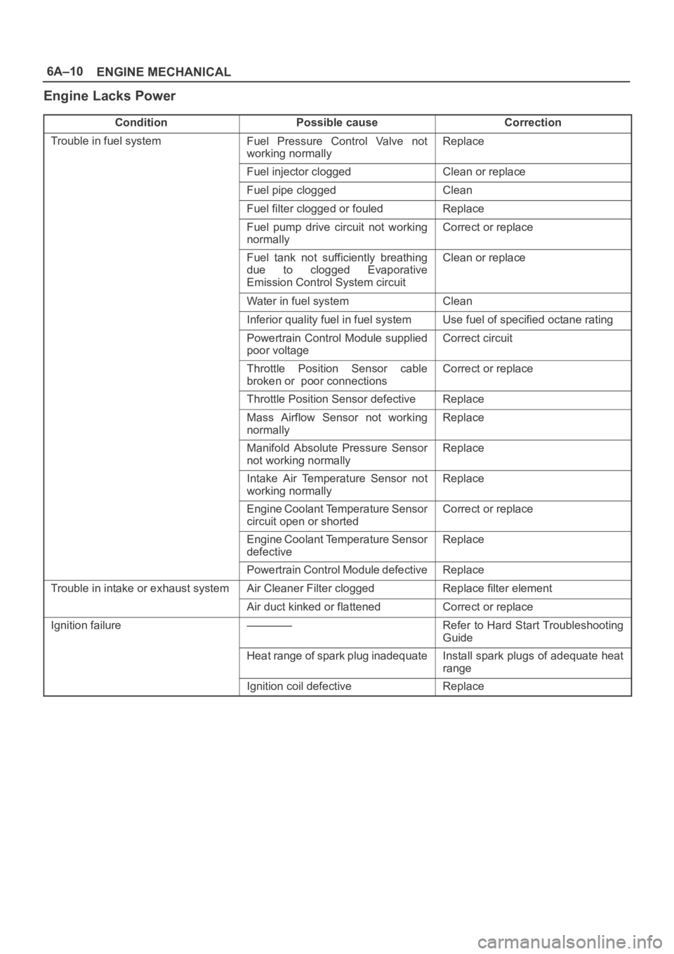
Engine Lacks Power
ConditionPossible causeCorrection
Trouble in fuel systemFuel Pressure Control Valve not
working normallyReplace
Fuel injector cloggedClean or replace
Fuel pipe cloggedClean
Fuel filter clogged or fouledReplace
Fuel pump drive circuit not working
normallyCorrect or replace
Fuel tank not sufficiently breathing
due to clogged Evaporative
Emission Control System circuitClean or replace
Water in fuel systemClean
Inferior quality fuel in fuel systemUse fuel of specified octane rating
Powertrain Control Module supplied
poor voltageCorrect circuit
Throttle Position Sensor cable
broken or poor connectionsCorrect or replace
Throttle Position Sensor defectiveReplace
Mass Airflow Sensor not working
normallyReplace
Manifold Absolute Pressure Sensor
not working normallyReplace
Intake Air Temperature Sensor not
working normallyReplace
Engine Coolant Temperature Sensor
circuit open or shortedCorrect or replace
Engine Coolant Temperature Sensor
defectiveReplace
Powertrain Control Module defectiveReplace
Trouble in intake or exhaust systemAir Cleaner Filter cloggedReplace filter element
Air duct kinked or flattenedCorrect or replace
Ignition failure————Refer to Hard Start Troubleshooting
Guide
Heat range of spark plug inadequateInstall spark plugs of adequate heat
range
Ignition coil defectiveReplace
Page 4507 of 6000
6A–11
ENGINE MECHANICAL
Condition CorrectionPossible cause
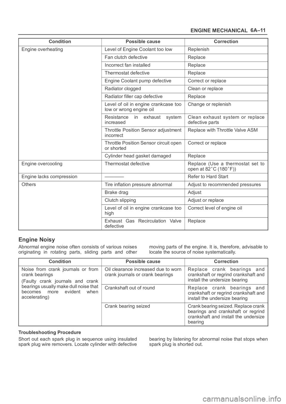
Engine overheatingLevel of Engine Coolant too lowReplenish
Fan clutch defectiveReplace
Incorrect fan installedReplace
Thermostat defectiveReplace
Engine Coolant pump defectiveCorrect or replace
Radiator cloggedClean or replace
Radiator filler cap defectiveReplace
Level of oil in engine crankcase too
low or wrong engine oilChange or replenish
Resistance in exhaust system
increasedClean exhaust system or replace
defective parts
Throttle Position Sensor adjustment
incorrectReplace with Throttle Valve ASM
Throttle Position Sensor circuit open
or shortedCorrect or replace
Cylinder head gasket damagedReplace
Engine overcoolingThermostat defectiveReplace (Use a thermostat set to
open at 82
C (180F))
Engine lacks compression————Refer to Hard Start
OthersTire inflation pressure abnormalAdjust to recommended pressures
Brake dragAdjust
Clutch slippingAdjust or replace
Level of oil in engine crankcase too
highCorrect level of engine oil
Exhaust Gas Recirculation Valve
defectiveReplace
Engine Noisy
Abnormal engine noise often consists of various noises
originating in rotating parts, sliding parts and othermoving parts of the engine. It is, therefore, advisable to
locate the source of noise systematically.
Condition
Possible causeCorrection
Noise from crank journals or from
crank bearings
(Faulty crank journals and crankOil clearance increased due to worn
crank journals or crank bearingsReplace crank bearings and
crankshaft or regrind crankshaft and
install the undersize bearing
yj
bearings usually make dull noise that
becomes more evident when
accelerating)Crankshaft out of roundReplace crank bearings and
crankshaft or regrind crankshaft and
install the undersize bearing
Crank bearing seizedCrank bearing seized. Replace crank
bearings and crankshaft or regrind
crankshaft and install the undersize
bearing
Troubleshooting Procedure
Short out each spark plug in sequence using insulated
spark plug wire removers. Locate cylinder with defectivebearing by listening for abnormal noise that stops when
spark plug is shorted out.
Page 4510 of 6000
6A–14
ENGINE MECHANICAL
Condition CorrectionPossible cause
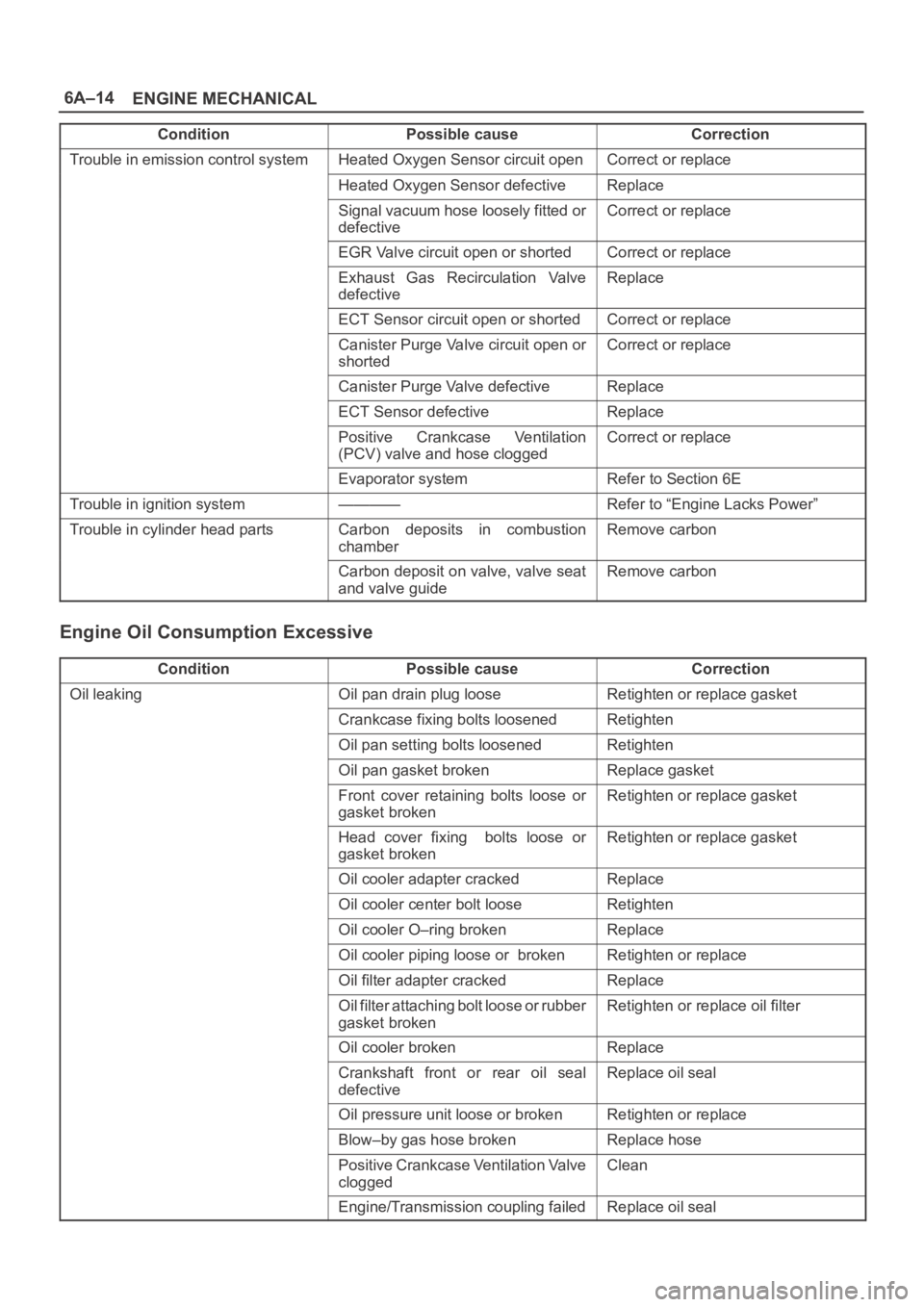
Trouble in emission control systemHeated Oxygen Sensor circuit openCorrect or replace
Heated Oxygen Sensor defectiveReplace
Signal vacuum hose loosely fitted or
defectiveCorrect or replace
EGR Valve circuit open or shortedCorrect or replace
Exhaust Gas Recirculation Valve
defectiveReplace
ECT Sensor circuit open or shortedCorrect or replace
Canister Purge Valve circuit open or
shortedCorrect or replace
Canister Purge Valve defectiveReplace
ECT Sensor defectiveReplace
Positive Crankcase Ventilation
(PCV) valve and hose cloggedCorrect or replace
Evaporator systemRefer to Section 6E
Trouble in ignition system————Refer to “Engine Lacks Power”
Trouble in cylinder head partsCarbon deposits in combustion
chamberRemove carbon
Carbon deposit on valve, valve seat
and valve guideRemove carbon
Engine Oil Consumption Excessive
ConditionPossible causeCorrection
Oil leakingOil pan drain plug looseRetighten or replace gasket
Crankcase fixing bolts loosenedRetighten
Oil pan setting bolts loosenedRetighten
Oil pan gasket brokenReplace gasket
Front cover retaining bolts loose or
gasket brokenRetighten or replace gasket
Head cover fixing bolts loose or
gasket brokenRetighten or replace gasket
Oil cooler adapter crackedReplace
Oil cooler center bolt looseRetighten
Oil cooler O–ring brokenReplace
Oil cooler piping loose or brokenRetighten or replace
Oil filter adapter crackedReplace
Oil filter attaching bolt loose or rubber
gasket brokenRetighten or replace oil filter
Oil cooler brokenReplace
Crankshaft front or rear oil seal
defectiveReplace oil seal
Oil pressure unit loose or brokenRetighten or replace
Blow–by gas hose brokenReplace hose
Positive Crankcase Ventilation Valve
cloggedClean
Engine/Transmission coupling failedReplace oil seal
Page 4512 of 6000
6A–16
ENGINE MECHANICAL
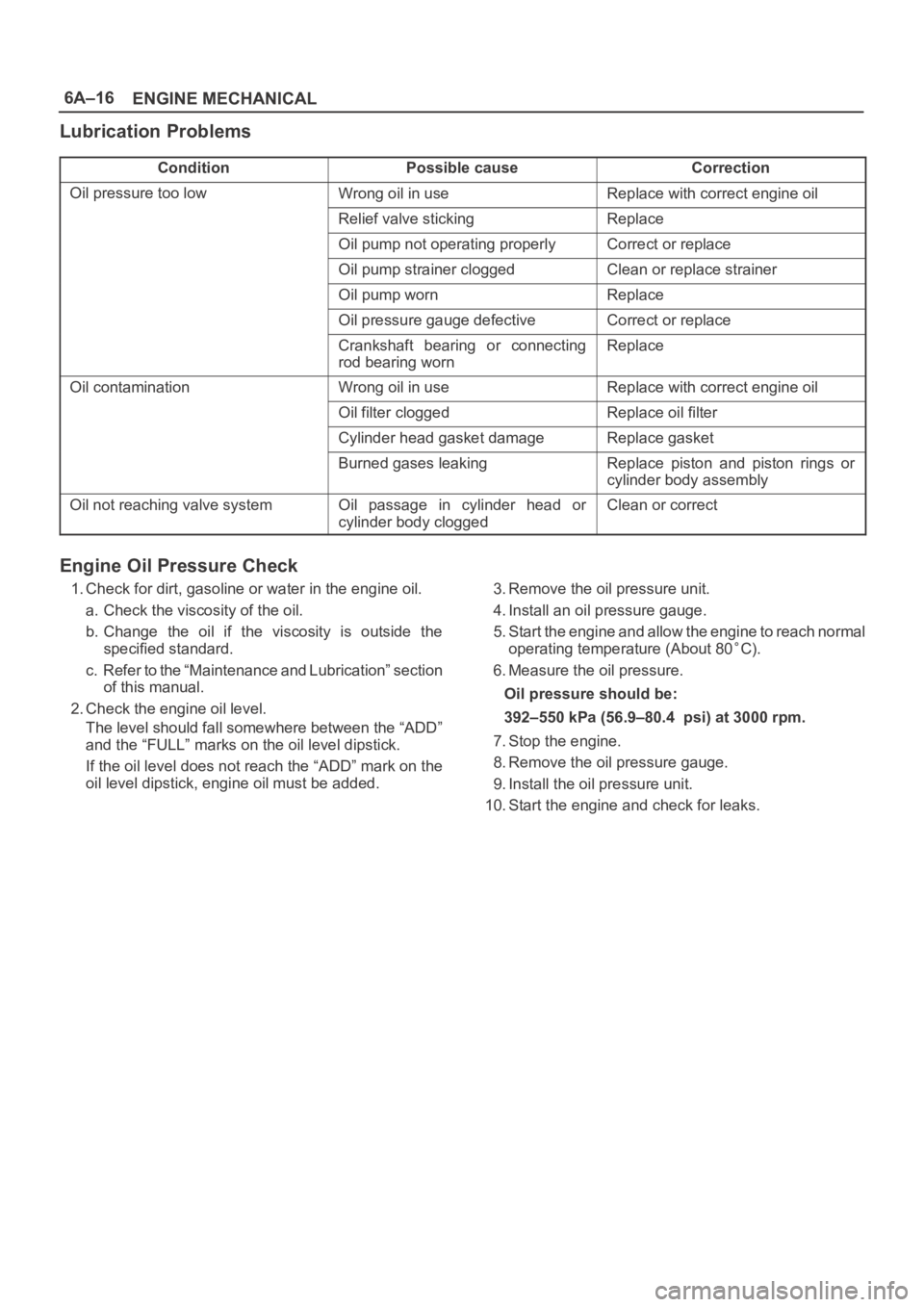
Lubrication Problems
ConditionPossible causeCorrection
Oil pressure too lowWrong oil in useReplace with correct engine oil
Relief valve stickingReplace
Oil pump not operating properlyCorrect or replace
Oil pump strainer cloggedClean or replace strainer
Oil pump wornReplace
Oil pressure gauge defectiveCorrect or replace
Crankshaft bearing or connecting
rod bearing wornReplace
Oil contaminationWrong oil in useReplace with correct engine oil
Oil filter cloggedReplace oil filter
Cylinder head gasket damageReplace gasket
Burned gases leakingReplace piston and piston rings or
cylinder body assembly
Oil not reaching valve systemOil passage in cylinder head or
cylinder body cloggedClean or correct
Engine Oil Pressure Check
1. Check for dirt, gasoline or water in the engine oil.
a. Check the viscosity of the oil.
b. Change the oil if the viscosity is outside the
specified standard.
c. Refer to the “Maintenance and Lubrication” section
of this manual.
2. Check the engine oil level.
The level should fall somewhere between the “ADD”
and the “FULL” marks on the oil level dipstick.
If the oil level does not reach the “ADD” mark on the
oil level dipstick, engine oil must be added.3. Remove the oil pressure unit.
4. Install an oil pressure gauge.
5. Start the engine and allow the engine to reach normal
operating temperature (About 80
C).
6. Measure the oil pressure.
Oil pressure should be:
392–550 kPa (56.9–80.4 psi) at 3000 rpm.
7. Stop the engine.
8. Remove the oil pressure gauge.
9. Install the oil pressure unit.
10. Start the engine and check for leaks.
Page 4514 of 6000
6A–18
ENGINE MECHANICAL
Cylinder Head Cover LH
Removal
1. Disconnect battery ground cable.
2. Drain engine coolant from faucet bottom of radiator.
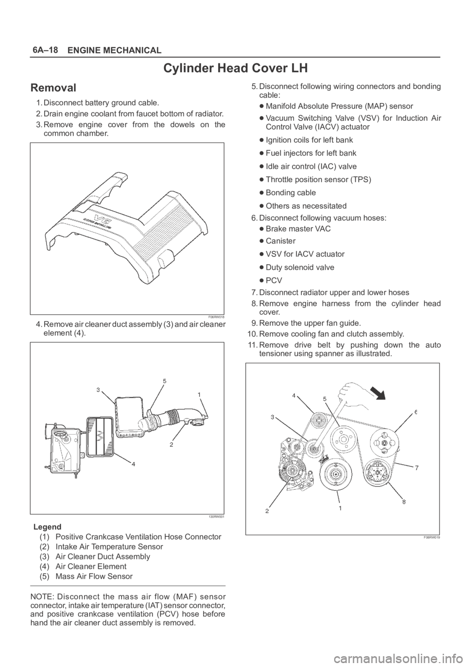
3. Remove engine cover from the dowels on the
common chamber.
F06RW018
4. Remove air cleaner duct assembly (3) and air cleaner
element (4).
130RW001
Legend
(1) Positive Crankcase Ventilation Hose Connector
(2) Intake Air Temperature Sensor
(3) Air Cleaner Duct Assembly
(4) Air Cleaner Element
(5) Mass Air Flow Sensor
NOTE: Disconnect the mass air flow (MAF) sensor
connector, intake air temperature (IAT) sensor connector,
and positive crankcase ventilation (PCV) hose before
hand the air cleaner duct assembly is removed.5. Disconnect following wiring connectors and bonding
cable:
Manifold Absolute Pressure (MAP) sensor
Vacuum Switching Valve (VSV) for Induction Air
Control Valve (IACV) actuator
Ignition coils for left bank
Fuel injectors for left bank
Idle air control (IAC) valve
Throttle position sensor (TPS)
Bonding cable
Others as necessitated
6. Disconnect following vacuum hoses:
Brake master VAC
Canister
VSV for IACV actuator
Duty solenoid valve
PCV
7. Disconnect radiator upper and lower hoses
8. Remove engine harness from the cylinder head
cover.
9. Remove the upper fan guide.
10. Remove cooling fan and clutch assembly.
11. Remove drive belt by pushing down the auto
tensioner using spanner as illustrated.
F06RW019
Page 4578 of 6000
6A–82
ENGINE MECHANICAL
4. Reinstall the rod caps (12) to their original
positions.
Tighten the rod cap nuts.
Torque: 54 Nꞏm (5.5 Kgꞏm/40 lb ft)
NOTE: Do not allow the crankshaft to rotate.
5. Remove the rod caps.
6. Measure the width of the plastigage and
determine the oil clearance. If the oil clearance
exceeds the limit, replace the rod bearing as a
set.
Standard : 0.019 mm–0.043 mm
(0.0007 in–0.0017 in)
Limit : 0.08 mm (0.003 in)
015RS008
7. Clean the plastigage from the bearings and the
crankshaft pins.
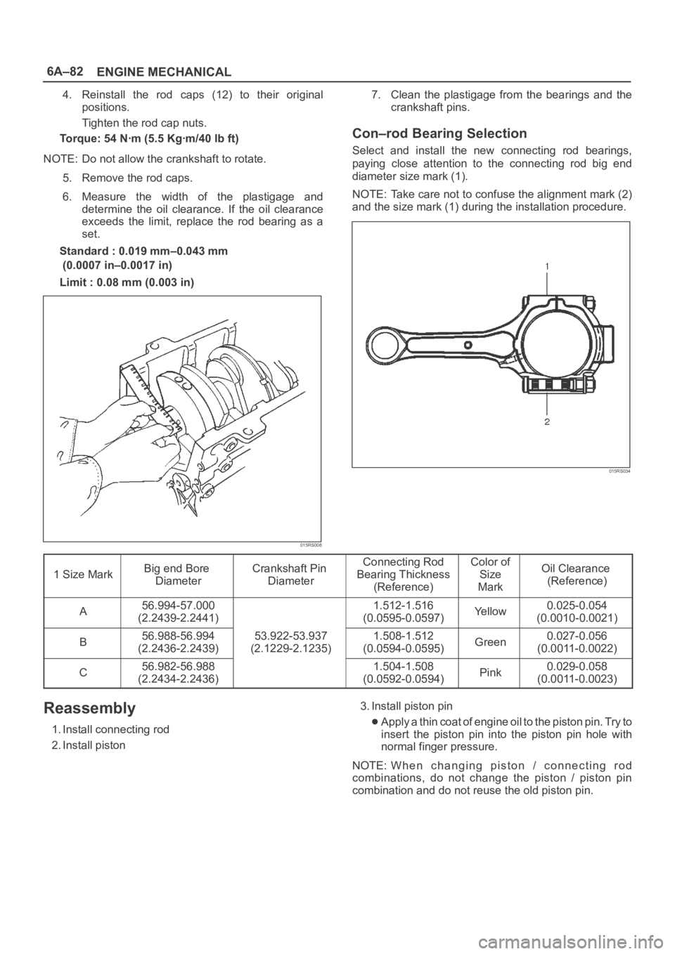
Con–rod Bearing Selection
Select and install the new connecting rod bearings,
paying close attention to the connecting rod big end
diameter size mark (1).
NOTE: Take care not to confuse the alignment mark (2)
and the size mark (1) during the installation procedure.
015RS034
1 Size MarkBig end Bore
DiameterCrankshaft Pin
DiameterConnecting Rod
Bearing Thickness
(Reference)Color of
Size
MarkOil Clearance
(Reference)
A56.994-57.000
(2.2439-2.2441)1.512-1.516
(0.0595-0.0597)Ye l l o w0.025-0.054
(0.0010-0.0021)
B56.988-56.994
(2.2436-2.2439)53.922-53.937
(2.1229-2.1235)1.508-1.512
(0.0594-0.0595)Green0.027-0.056
(0.0011-0.0022)
C56.982-56.988
(2.2434-2.2436)1.504-1.508
(0.0592-0.0594)Pink0.029-0.058
(0.0011-0.0023)
Reassembly
1. Install connecting rod
2. Install piston3. Install piston pinApply a thin coat of engine oil to the piston pin. Try to
insert the piston pin into the piston pin hole with
normal finger pressure.
NOTE: When changing piston / connecting rod
combinations, do not change the piston / piston pin
combination and do not reuse the old piston pin.
Page 4582 of 6000
6A–86
ENGINE MECHANICAL
11. Remove rear oil seal retainer assembly.
12. Remove main bearing cap.
13. Remove crankshaft.
14. Remove cylinder block.
Inspection and Repair
1. Remove the cylinder head gasket and any other
material adhering to the upper surface of the cylinder
block. Be very careful not to allow any material to
accidentally drop into the cylinder block. Be very
careful not to scratch the cylinder block.
2. Carefully remove the oil pump, rear oil seal retainer,
and crankcase assembly installation surface seal.
3. Wipe the cylinder block clean.
4. Visually inspect the cylinder block. If necessary, use a
flaw detector to perform a dye penetrate and
hydraulic (or air pressure) test. If cracking or other
damage is discovered, the cylinder block must either
be repaired or replaced.
Flatness
1. Using a straight–edge and feeler gauge, check that
the upper surface of the cylinder block is not warped.
CAUTION: Be very careful not to allow any material
to accidentally drop into the upper surface of the
cylinder block. Be very careful not to scratch the
upper surface of the cylinder block.
2. The cylinder block must be reground or replaced if the
warpage exceeds the limit.
Warpage
Limit : 0.15 mm (0.0059 in)
Maximum repairable limit: 0.15 mm (0.0059 in)
012RS004
Cylinder Bore
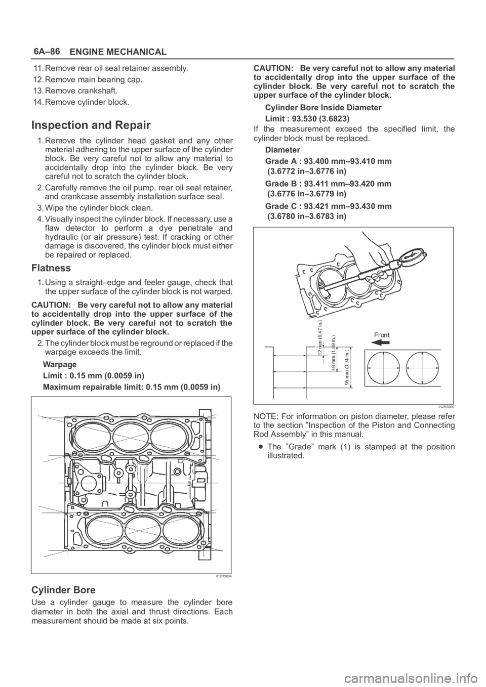
Use a cylinder gauge to measure the cylinder bore
diameter in both the axial and thrust directions. Each
measurement should be made at six points.CAUTION: Be very careful not to allow any material
to accidentally drop into the upper surface of the
cylinder block. Be very careful not to scratch the
upper surface of the cylinder block.
Cylinder Bore Inside Diameter
Limit : 93.530 (3.6823)
If the measurement exceed the specified limit, the
cylinder block must be replaced.
Diameter
Grade A : 93.400 mm–93.410 mm
(3.6772 in–3.6776 in)
Grade B : 93.411 mm–93.420 mm
(3.6776 in–3.6779 in)
Grade C : 93.421 mm–93.430 mm
(3.6780 in–3.6783 in)
012RS005
NOTE: For information on piston diameter, please refer
to the section ”Inspection of the Piston and Connecting
Rod Assembly” in this manual.
The ”Grade” mark (1) is stamped at the position
illustrated.
Page 4599 of 6000
6B–6
ENGINE COOLING
Draining and Refilling Cooling
System
Before draining the cooling system, inspect the system
and perform any necessary service to ensure that it is
clean, does not leak and is in proper working order. The
engine coolant (EC) level should be between the “MIN”
and “MAX” lines of reserve tank when the engine is cold.
If low, check for leakage and add EC up to the “MAX” line.
There should not be any excessive deposit of rust or
scales around the radiator cap or radiator filler hole, and
the EC should also be free from oil.
Replace the EC if excessively dirty.
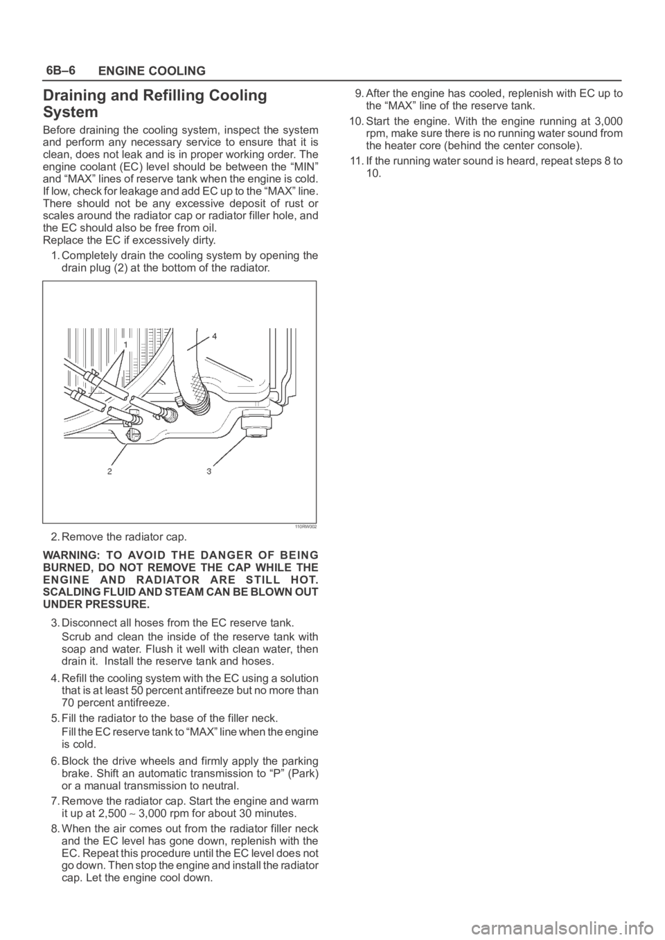
1. Completely drain the cooling system by opening the
drain plug (2) at the bottom of the radiator.
110RW002
2. Remove the radiator cap.
WARNING: TO AVOID THE DANGER OF BEING
BURNED, DO NOT REMOVE THE CAP WHILE THE
ENGINE AND RADIATOR ARE STILL HOT.
SCALDING FLUID AND STEAM CAN BE BLOWN OUT
UNDER PRESSURE.
3. Disconnect all hoses from the EC reserve tank.
Scrub and clean the inside of the reserve tank with
soap and water. Flush it well with clean water, then
drain it. Install the reserve tank and hoses.
4. Refill the cooling system with the EC using a solution
that is at least 50 percent antifreeze but no more than
70 percent antifreeze.
5. Fill the radiator to the base of the filler neck.
Fill the EC reserve tank to “MAX” line when the engine
is cold.
6. Block the drive wheels and firmly apply the parking
brake. Shift an automatic transmission to “P” (Park)
or a manual transmission to neutral.
7. Remove the radiator cap. Start the engine and warm
it up at 2,500
3,000 rpm for about 30 minutes.
8. When the air comes out from the radiator filler neck
and the EC level has gone down, replenish with the
EC. Repeat this procedure until the EC level does not
go down. Then stop the engine and install the radiator
cap. Let the engine cool down.9. After the engine has cooled, replenish with EC up to
the “MAX” line of the reserve tank.
10. Start the engine. With the engine running at 3,000
rpm, make sure there is no running water sound from
the heater core (behind the center console).
11. If the running water sound is heard, repeat steps 8 to
10.