Page 5823 of 6000

7A–42 AUTOMATIC TRANSMISSION (AW30-40LE)
DTC P0748 (FLASHING CODE 35) PRESSURE CONTROL SOLENOID FAILURE (STH)
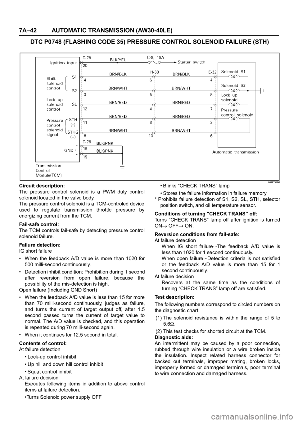
D07RY00047Circuit description:
The pressure control solenoid is a PWM duty control
solenoid located in the valve body.
The pressure control solenoid is a TCM-controled device
used to regulate transmission throttle pressure by
energizing current from the TCM.
Fail-safe control:
The TCM controls fail-safe by detecting pressure control
solenoid failure.
Failure detection:
IG shor t failure
• When the feedback A/D value is more than 1020 for
500 milli-second continuously.
• Detection inhibit condition: Prohibition during 1 second
after reversion from open failure, because the
possibility of the mis-detection is high.
Open failure (Including GND Shor t)
• When the feedback A/D value is less than 15 for more
than 70 milli-second continuously, judges as faliure,
and turns the current of target output off, after 1.5
second passed turns the current of target value to
normal. The A/D value is checked, and this operation
is repeated during 70 milli-second again.
• When it continues for 12.5 second in total.
Contents of control:
At failure detection
• Lock-up control inhibit
• Up hill and down hill control inhibit
• Squat control inhibit
At failure decision
Executes following items in addition to above control
items at failure detection.
•Turns Solenoid power supply OFF• Blinks "CHECK TRANS" lamp
• Stores the failure information in failure memory
* Prohibits failure detection of S1, S2, SL, STH, selector
position switch, and oil temperature sensor.
Conditions of turning "CHECK TRANS" off:
Turns "CHECK TRANS" lamp off after ignition is turned
ON
OFF ON.
Reversion conditions from fail-safe:
At failure detection
W h e n I G sh o r t fa i l u re ꞏꞏꞏT h e fe e d ba ck A / D va l u e i s
less than 1020 for 1 second continuously.
W h e n o p e n fa i l u re ꞏꞏꞏD e t e c t i o n c r i t e r i a i s n o t s a t i s f i e d
or the feedback A/D value is more than 15 for 1
second continuously.
At failure decision
Recovers at the same time as the conditions of
turning “CHECK TRANS” lamp off are satisfied.
Test description:
The following numbers correspond to circled numbers on
the diagnostic char t.
(1) The solenoid resistance is within the range of 5 to
5.6
.
(2) This test checks for shor ted circuit at the TCM.
Diagnostic aids:
An intermittent may be caused by a poor connection,
rubbed through wire insulation or a wire broken inside
the insulation. Inspect related harness connector for
backed out terminals, improper mating, broken locks,
improperly formed or damaged terminals, poor terminal
to wire connection and damaged harness.
Page 5846 of 6000

AUTOMATIC TRANSMISSION (AW30-40LE) 7A–65
F07RY00004
HYDRAULIC TEST
PREPARATION
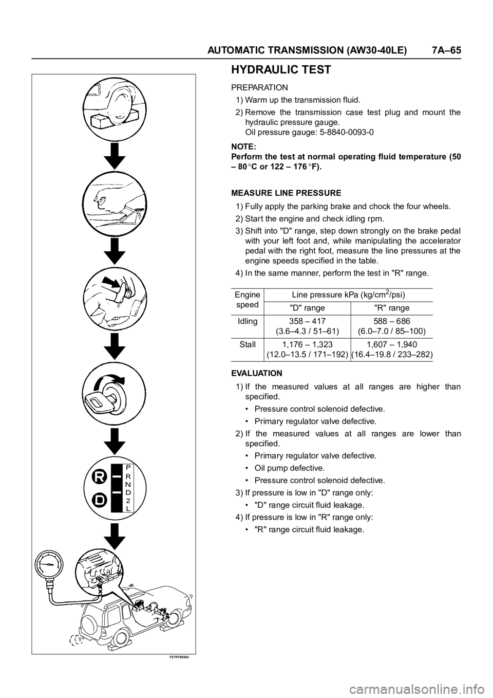
1) Warm up the transmission fluid.
2) Remove the transmission case test plug and mount the
hydraulic pressure gauge.
Oil pressure gauge: 5-8840-0093-0
NOTE:
Perform the test at normal operating fluid temperature (50
– 80
C or 122 – 176F).
MEASURE LINE PRESSURE
1) Fully apply the parking brake and chock the four wheels.
2) Start the engine and check idling rpm.
3) Shift into "D" range, step down strongly on the brake pedal
with your left foot and, while manipulating the accelerator
pedal with the right foot, measure the line pressures at the
engine speeds specified in the table.
4) In the same manner, perform the test in "R" range.
EVALUATION
1) If the measured values at all ranges are higher than
specified.
• Pressure control solenoid defective.
• Primary regulator valve defective.
2) If the measured values at all ranges are lower than
specified.
• Primary regulator valve defective.
• Oil pump defective.
• Pressure control solenoid defective.
3) If pressure is low in "D" range only:
• "D" range circuit fluid leakage.
4) If pressure is low in "R" range only:
• "R" range circuit fluid leakage. Engine
speedLine pressure kPa (kg/cm
2/psi)
"D" range "R" range
Idling 358 – 417
(3.6–4.3 / 51–61)588 – 686
(6.0–7.0 / 85–100)
Stall 1,176 – 1,323
(12.0–13.5 / 171–192)1,607 – 1,940
(16.4–19.8 / 233–282)
Page 5859 of 6000
7A–78 AUTOMATIC TRANSMISSION (AW30-40LE)
F07RY00019
225RY00001
220RY00001
244RX00001
PATTERN SELECT SWITCH INSPECTION
Inspect that there is continuity between each terminals.
OVERDRIVE OFF SWITCH INSPECTION
Inspect that there is continuity between terminals 2 and 4.
SOLENOID INSPECTION
1. Resistance check
• Using an ohmmeter, check the resistance between each
terminals (S1/S2/SL) and body.
• Using an ohmmeter, check the resistance between
terminals (STH) and (STHG).
NOTE:
If the pressure contorl solenoid resistance is not within
specification, replace the valve body assembly.
2. Operation Check
Check the solenoid operation by blowing into an oil hole as
shown in the figure.
Solenoid S1 and S2 (Normal close type)
Solenoid S1, S2 and Lock-up
solenoid resistance11 - 15(20C)
12 - 16
(40C)
Pressure control solenoid
resistance5 - 5.6
(20C)
5.4 - 6.1
(40C)
When battery terminal is
disconnectedNo air leaks
When battery terminal is
connectedAir passes through
Page 5999 of 6000

7A1–6
TRANSMISSION CONTROL SYSTEM (4L30–E)
Shift Control
The transmission gear is shifted according to the shift
pattern selected by the driver. In shifting gears, the gear
ratio is controlled by the ON/ OFF signal using the shift
solenoid A and the shift solenoid B.
Band Apply Control
The band apply is controlled when in the 3–2 downshift
(engine overrun prevention) and the garage shift (shock
control).
The band apply solenoid is controlled by the signal from
the Pulse Width Modulation (PWM) to regulate the flow of
the oil.
Torque Converter Clutch Control
The clutch ON/OFF is controlled by moving the converter
clutch valve through shifting Torque Converter Clutch
(TCC) solenoid using the ON/OFF signal.
Line Pressure Control
The throttle signal allows the current signal to be sent to
the force motor. After receiving the current signal, the
force motor activates the pressure regulator valve to
regulate the line pressure.
On–Board Diagnostic System
Several malfunction displays can be stored in the
Powertrain Control Module (PCM) memory, and read out
of it afterward.The serial data lines, which are required for the testing of
the final assembly and the coupling to other electronic
modules, can be regulated by this function.
Fail Safe Mechanism
If there is a problem in the transmission system, the PCM
will go into a “backup” mode.
The vehicle can still be driven, but the driver must use the
select lever to shift gears.
Torque Management Control
The transmission control side sends the absolute spark
advance signal to the engine control side while the
transmission is being shifted. This controls the engine
spark timing in compliance with the vehicle running
condition to reduce the shocks caused by the change of
speed.
ATF Warning Control
The oil temperature sensor detects the ATF oil
temperature to control the oil temperature warning, TCC,
and the winter mode.
ABS Control (If equipped)
When the select lever is at “L” or “R” range, a signal is sent
to the ABS controller as one of the ABS control
conditions.