Page 4958 of 6000
6E–301 ENGINE DRIVEABILITY AND EMISSIONS
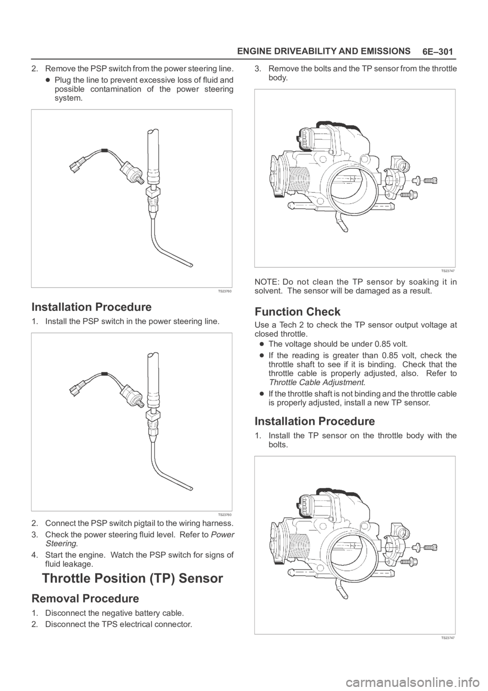
2. Remove the PSP switch from the power steering line.
Plug the line to prevent excessive loss of fluid and
possible contamination of the power steering
system.
TS23760
Installation Procedure
1. Install the PSP switch in the power steering line.
TS23760
2. Connect the PSP switch pigtail to the wiring harness.
3. Check the power steering fluid level. Refer to
Power
Steering
.
4. Start the engine. Watch the PSP switch for signs of
fluid leakage.
Throttle Position (TP) Sensor
Removal Procedure
1. Disconnect the negative battery cable.
2. Disconnect the TPS electrical connector.3. Remove the bolts and the TP sensor from the throttle
body.
TS23747
NOTE: Do not clean the TP sensor by soaking it in
solvent. The sensor will be damaged as a result.
Function Check
Use a Tech 2 to check the TP sensor output voltage at
closed throttle.
The voltage should be under 0.85 volt.
If the reading is greater than 0.85 volt, check the
throttle shaft to see if it is binding. Check that the
throttle cable is properly adjusted, also. Refer to
Throttle Cable Adjustment.
If the throttle shaft is not binding and the throttle cable
is properly adjusted, install a new TP sensor.
Installation Procedure
1. Install the TP sensor on the throttle body with the
bolts.
TS23747
Page 4959 of 6000
6E–302
ENGINE DRIVEABILITY AND EMISSIONS
2. Connect the TP electrical connector.
3. Install the negative battery cable.
Vehicle Speed Sensor (VSS)
Removal Procedure
CAUTION: The VSS is located on the right side of
the transfer case just ahead of the rear propeller
shaft and very close to the exhaust pipes. Be sure
that the exhaust pipes are cool enough to touch
before trying to remove the VSS. If the pipes are hot,
you could be burned.
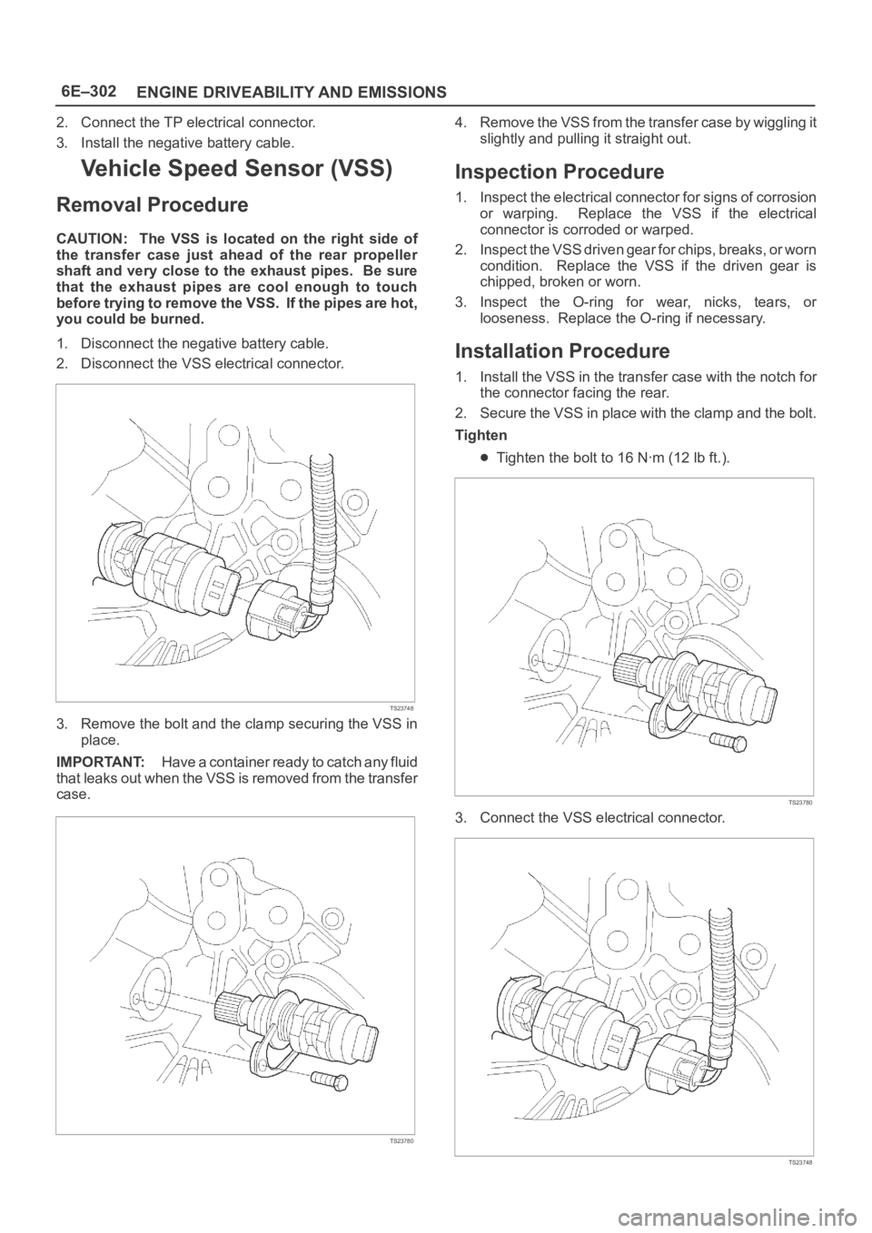
1. Disconnect the negative battery cable.
2. Disconnect the VSS electrical connector.
TS23748
3. Remove the bolt and the clamp securing the VSS in
place.
IMPORTANT:H a v e a c o n t a i n e r r e a d y t o c a t c h a n y f l u i d
that leaks out when the VSS is removed from the transfer
case.
TS23780
4. Remove the VSS from the transfer case by wiggling it
slightly and pulling it straight out.
Inspection Procedure
1. Inspect the electrical connector for signs of corrosion
or warping. Replace the VSS if the electrical
connector is corroded or warped.
2. Inspect the VSS driven gear for chips, breaks, or worn
condition. Replace the VSS if the driven gear is
chipped, broken or worn.
3. Inspect the O-ring for wear, nicks, tears, or
looseness. Replace the O-ring if necessary.
Installation Procedure
1. Install the VSS in the transfer case with the notch for
the connector facing the rear.
2. Secure the VSS in place with the clamp and the bolt.
Tighten
Tighten the bolt to 16 Nꞏm (12 lb ft.).
TS23780
3. Connect the VSS electrical connector.
TS23748
Page 4960 of 6000
6E–303 ENGINE DRIVEABILITY AND EMISSIONS
4. Check the transfer case oil level. Add fluid if
necessary.
5. Connect the negative battery cable.
Air Cleaner/Air Filter
Removal Procedure
1. Loosen the clamp between the air cleaner lid and the
mass air flow sensor.
2. Release the four latches securing the lid to the air
cleaner housing.
3. Remove the air cleaner lid.
TS23973
4. Remove the air filter element.
TS23794
5. Remove the retaining bolts and the air cleaner
housing from the vehicle.
130RT002
Installation Procedure
1. Install the air cleaner housing in the vehicle with the
retaining bolts.
130RT002
Page 4961 of 6000
6E–304
ENGINE DRIVEABILITY AND EMISSIONS
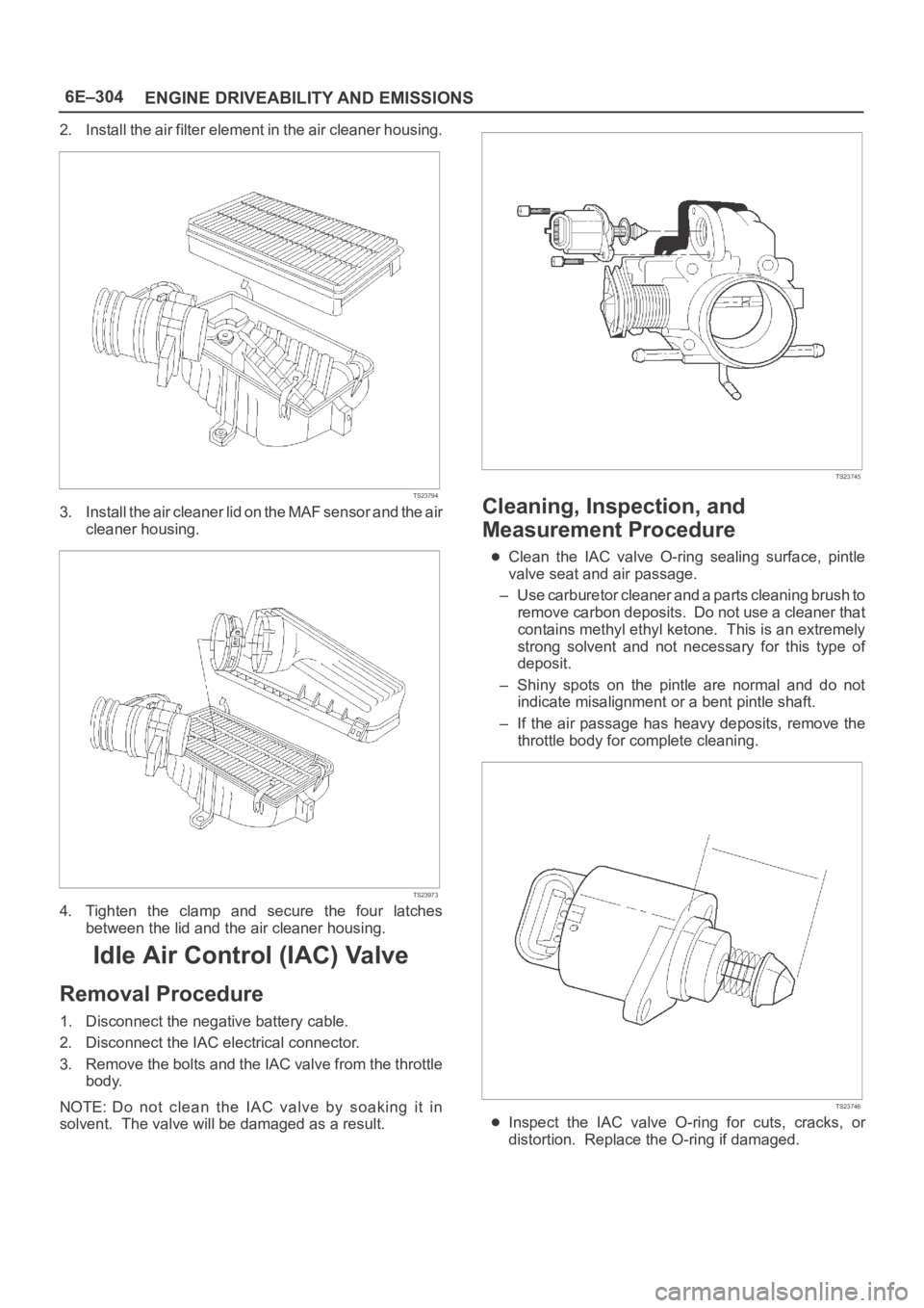
2. Install the air filter element in the air cleaner housing.
TS23794
3. Install the air cleaner lid on the MAF sensor and the air
cleaner housing.
TS23973
4. Tighten the clamp and secure the four latches
between the lid and the air cleaner housing.
Idle Air Control (IAC) Valve
Removal Procedure
1. Disconnect the negative battery cable.
2. Disconnect the IAC electrical connector.
3. Remove the bolts and the IAC valve from the throttle
body.
NOTE: Do not clean the IAC valve by soaking it in
solvent. The valve will be damaged as a result.
TS23745
Cleaning, Inspection, and
Measurement Procedure
Clean the IAC valve O-ring sealing surface, pintle
valve seat and air passage.
– Use carburetor cleaner and a parts cleaning brush to
remove carbon deposits. Do not use a cleaner that
contains methyl ethyl ketone. This is an extremely
strong solvent and not necessary for this type of
deposit.
– Shiny spots on the pintle are normal and do not
indicate misalignment or a bent pintle shaft.
– If the air passage has heavy deposits, remove the
throttle body for complete cleaning.
TS23746
Inspect the IAC valve O-ring for cuts, cracks, or
distortion. Replace the O-ring if damaged.
Page 4977 of 6000
6E–320
ENGINE DRIVEABILITY AND EMISSIONS
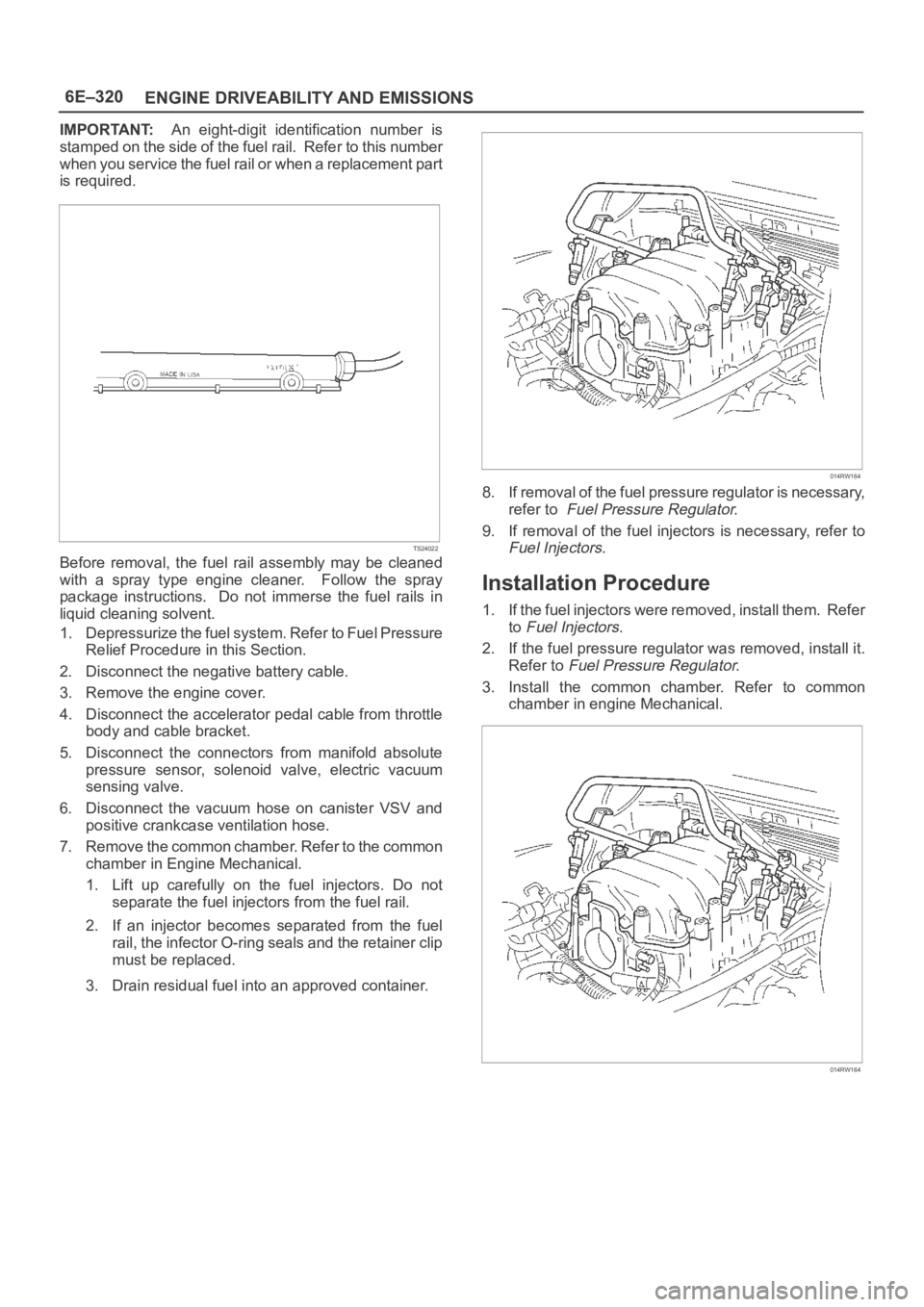
IMPORTANT:An eight-digit identification number is
stamped on the side of the fuel rail. Refer to this number
when you service the fuel rail or when a replacement part
is required.
TS24022
Before removal, the fuel rail assembly may be cleaned
with a spray type engine cleaner. Follow the spray
package instructions. Do not immerse the fuel rails in
liquid cleaning solvent.
1. Depressurize the fuel system. Refer to Fuel Pressure
Relief Procedure in this Section.
2. Disconnect the negative battery cable.
3. Remove the engine cover.
4. Disconnect the accelerator pedal cable from throttle
body and cable bracket.
5. Disconnect the connectors from manifold absolute
pressure sensor, solenoid valve, electric vacuum
sensing valve.
6. Disconnect the vacuum hose on canister VSV and
positive crankcase ventilation hose.
7. Remove the common chamber. Refer to the common
chamber in Engine Mechanical.
1. Lift up carefully on the fuel injectors. Do not
separate the fuel injectors from the fuel rail.
2. If an injector becomes separated from the fuel
rail, the infector O-ring seals and the retainer clip
must be replaced.
3. Drain residual fuel into an approved container.
014RW164
8. If removal of the fuel pressure regulator is necessary,
refer to
Fuel Pressure Regulator.
9. If removal of the fuel injectors is necessary, refer to
Fuel Injectors.
Installation Procedure
1. If the fuel injectors were removed, install them. Refer
to
Fuel Injectors.
2. If the fuel pressure regulator was removed, install it.
Refer to
Fuel Pressure Regulator.
3. Install the common chamber. Refer to common
chamber in engine Mechanical.
014RW164
Page 4978 of 6000
6E–321 ENGINE DRIVEABILITY AND EMISSIONS
4. Connect the vacuum hose on Canister VSV and
positive crankcase ventilation hose.
5. Connect the connectors to manifold absolute
pressure sensor, solenoid valve, electric vacuum
sensing valve.
6. Connect the accelerator pedal cable to throttle body
and cable bracket.
7. Install the engine cover.
8. Connect the negative battery cable.
9. Crank the engine until it starts. Cranking the engine
may take longer than usual due to trapped air in the
fuel rail and in the injectors.
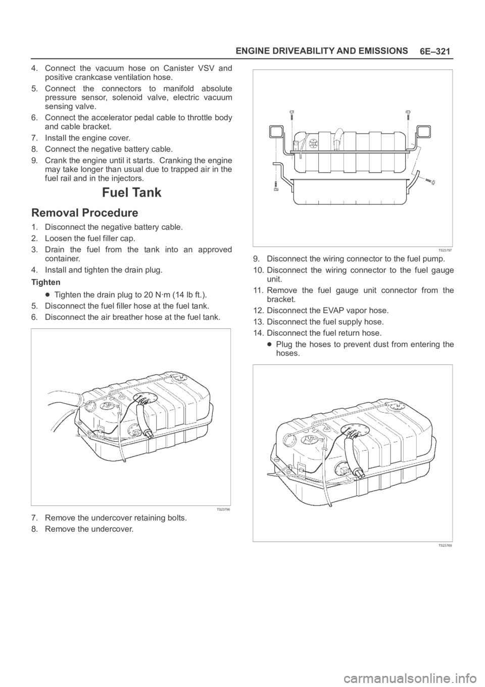
Fuel Tank
Removal Procedure
1. Disconnect the negative battery cable.
2. Loosen the fuel filler cap.
3. Drain the fuel from the tank into an approved
container.
4. Install and tighten the drain plug.
Tighten
Tighten the drain plug to 20 Nꞏm (14 lb ft.).
5. Disconnect the fuel filler hose at the fuel tank.
6. Disconnect the air breather hose at the fuel tank.
TS23796
7. Remove the undercover retaining bolts.
8. Remove the undercover.
TS23797
9. Disconnect the wiring connector to the fuel pump.
10. Disconnect the wiring connector to the fuel gauge
unit.
11. Remove the fuel gauge unit connector from the
bracket.
12. Disconnect the EVAP vapor hose.
13. Disconnect the fuel supply hose.
14. Disconnect the fuel return hose.
Plug the hoses to prevent dust from entering the
hoses.
TS23769
Page 4980 of 6000
6E–323 ENGINE DRIVEABILITY AND EMISSIONS
11. Connect the fuel filler fuse at the tank.
12. Connect the air breather hose at the tank.
TS23796
13. Fill the fuel tank with fuel.
14. Tighten the fuel filler cap.
15. Connect the negative battery cable.
Throttle Body (TB)
Removal Procedure
1. Disconnect the negative battery cable.
2. Drain the cooling system. Refer to
Cooling System.
3. Remove the accelerator cable assembly. Refer to
Accelerator Cable in Engine Speed Control System..
4. Disconnect the electrical connectors:
Throttle position (TP) sensor.
Idle air control (IAC) solenoid.
Intake air temperature (IAT) sensor. Refer to
Intake Air Temperature Sensor.
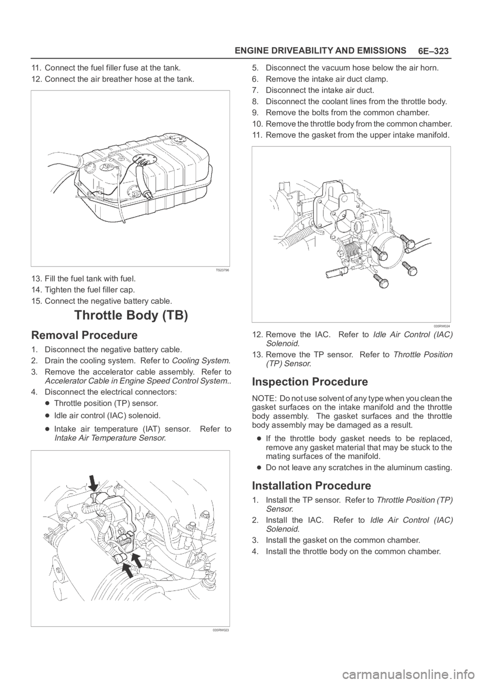
035RW023
5. Disconnect the vacuum hose below the air horn.
6. Remove the intake air duct clamp.
7. Disconnect the intake air duct.
8. Disconnect the coolant lines from the throttle body.
9. Remove the bolts from the common chamber.
10. Remove the throttle body from the common chamber.
11. Remove the gasket from the upper intake manifold.
035RW024
12. Remove the IAC. Refer to Idle Air Control (IAC)
Solenoid
.
13. Remove the TP sensor. Refer to
Throttle Position
(TP) Sensor
.
Inspection Procedure
NOTE: Do not use solvent of any type when you clean the
gasket surfaces on the intake manifold and the throttle
body assembly. The gasket surfaces and the throttle
body assembly may be damaged as a result.
If the throttle body gasket needs to be replaced,
remove any gasket material that may be stuck to the
mating surfaces of the manifold.
Do not leave any scratches in the aluminum casting.
Installation Procedure
1. Install the TP sensor. Refer to Throttle Position (TP)
Sensor
.
2. Install the IAC. Refer to
Idle Air Control (IAC)
Solenoid
.
3. Install the gasket on the common chamber.
4. Install the throttle body on the common chamber.
Page 4981 of 6000
6E–324
ENGINE DRIVEABILITY AND EMISSIONS
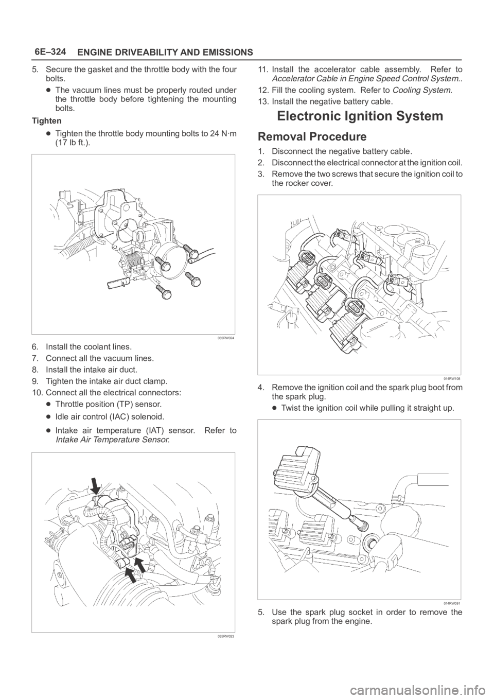
5. Secure the gasket and the throttle body with the four
bolts.
The vacuum lines must be properly routed under
the throttle body before tightening the mounting
bolts.
Tighten
Tighten the throttle body mounting bolts to 24 Nꞏm
(17 lb ft.).
035RW024
6. Install the coolant lines.
7. Connect all the vacuum lines.
8. Install the intake air duct.
9. Tighten the intake air duct clamp.
10. Connect all the electrical connectors:
Throttle position (TP) sensor.
Idle air control (IAC) solenoid.
Intake air temperature (IAT) sensor. Refer to
Intake Air Temperature Sensor.
035RW023
11. Install the accelerator cable assembly. Refer to
Accelerator Cable in Engine Speed Control System..
12. Fill the cooling system. Refer to
Cooling System.
13. Install the negative battery cable.
Electronic Ignition System
Removal Procedure
1. Disconnect the negative battery cable.
2. Disconnect the electrical connector at the ignition coil.
3. Remove the two screws that secure the ignition coil to
the rocker cover.
014RW108
4. Remove the ignition coil and the spark plug boot from
the spark plug.
Twist the ignition coil while pulling it straight up.
014RW091
5. Use the spark plug socket in order to remove the
spark plug from the engine.