1998 OPEL FRONTERA sensor
[x] Cancel search: sensorPage 5007 of 6000
6E–350
ENGINE DRIVEABILITY AND EMISSIONS
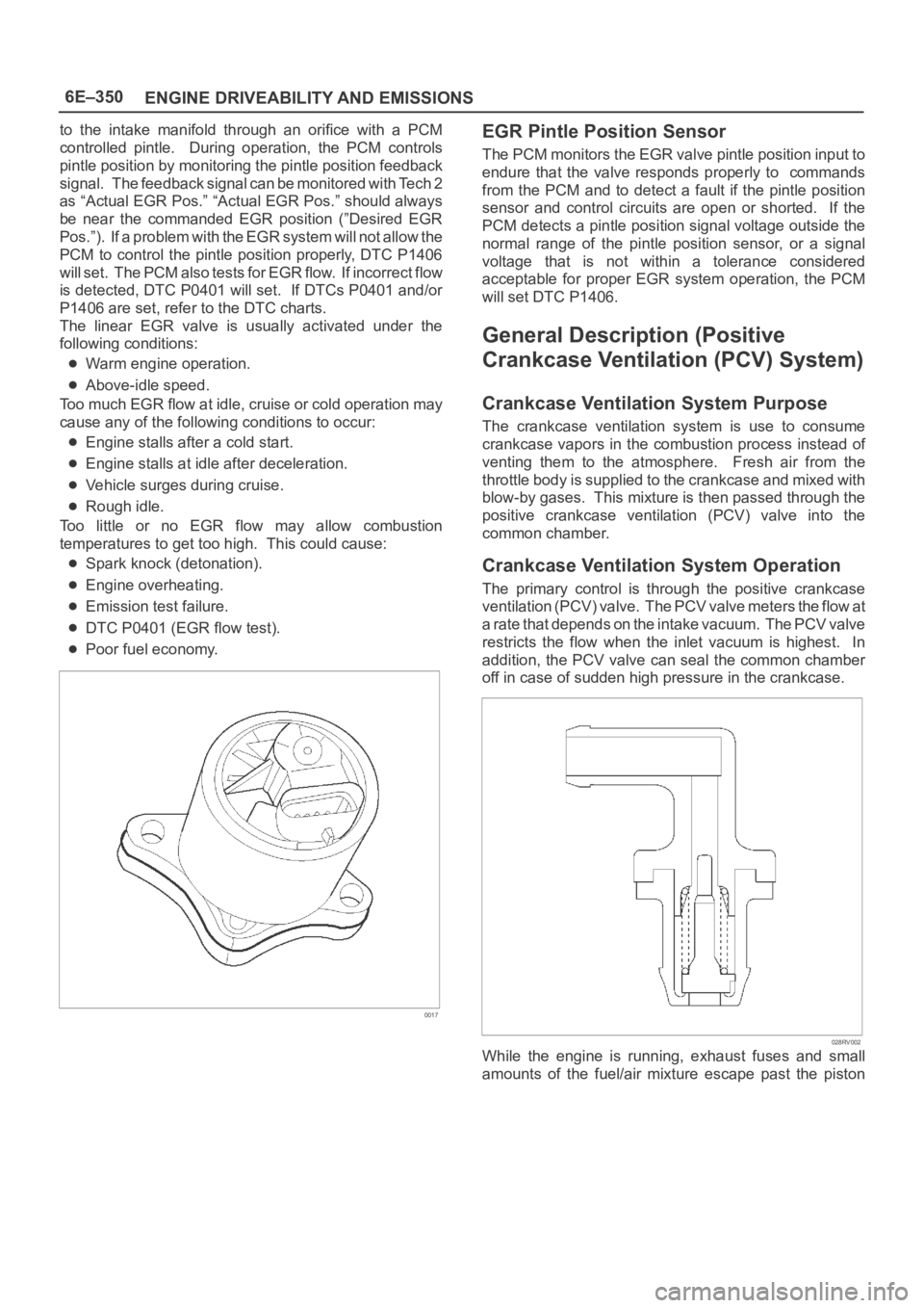
to the intake manifold through an orifice with a PCM
controlled pintle. During operation, the PCM controls
pintle position by monitoring the pintle position feedback
signal. The feedback signal can be monitored with Tech 2
as “Actual EGR Pos.” “Actual EGR Pos.” should always
be near the commanded EGR position (”Desired EGR
Pos.”). If a problem with the EGR system will not allow the
PCM to control the pintle position properly, DTC P1406
will set. The PCM also tests for EGR flow. If incorrect flow
is detected, DTC P0401 will set. If DTCs P0401 and/or
P1406 are set, refer to the DTC charts.
The linear EGR valve is usually activated under the
following conditions:
Warm engine operation.
Above-idle speed.
Too much EGR flow at idle, cruise or cold operation may
cause any of the following conditions to occur:
Engine stalls after a cold start.
Engine stalls at idle after deceleration.
Vehicle surges during cruise.
Rough idle.
Too little or no EGR flow may allow combustion
temperatures to get too high. This could cause:
Spark knock (detonation).
Engine overheating.
Emission test failure.
DTC P0401 (EGR flow test).
Poor fuel economy.
0017
EGR Pintle Position Sensor
The PCM monitors the EGR valve pintle position input to
endure that the valve responds properly to commands
from the PCM and to detect a fault if the pintle position
sensor and control circuits are open or shorted. If the
PCM detects a pintle position signal voltage outside the
normal range of the pintle position sensor, or a signal
voltage that is not within a tolerance considered
acceptable for proper EGR system operation, the PCM
will set DTC P1406.
General Description (Positive
Crankcase Ventilation (PCV) System)
Crankcase Ventilation System Purpose
The crankcase ventilation system is use to consume
crankcase vapors in the combustion process instead of
venting them to the atmosphere. Fresh air from the
throttle body is supplied to the crankcase and mixed with
blow-by gases. This mixture is then passed through the
positive crankcase ventilation (PCV) valve into the
common chamber.
Crankcase Ventilation System Operation
The primary control is through the positive crankcase
v e n t i l a t i o n ( P C V ) v a l v e . T h e PCV valve meters the flow at
a rate that depends on the intake vacuum. The PCV valve
restricts the flow when the inlet vacuum is highest. In
addition, the PCV valve can seal the common chamber
off in case of sudden high pressure in the crankcase.
028RV002
While the engine is running, exhaust fuses and small
amounts of the fuel/air mixture escape past the piston
Page 5010 of 6000
6E–353 ENGINE DRIVEABILITY AND EMISSIONS
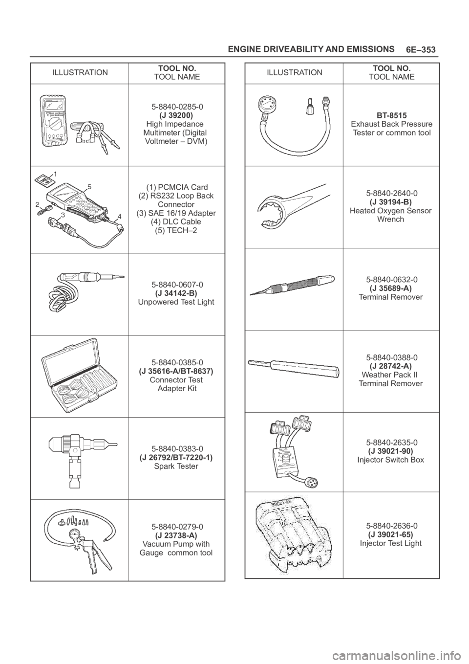
ILLUSTRATIONTOOL NO.
TOOL NAME
5-8840-0285-0
(J 39200)
High Impedance
Multimeter (Digital
Vo l t m e t e r – D V M )
(1) PCMCIA Card
(2) RS232 Loop Back
Connector
(3) SAE 16/19 Adapter
(4) DLC Cable
(5) TECH–2
5-8840-0607-0
(J 34142-B)
Unpowered Test Light
5-8840-0385-0
(J 35616-A/BT-8637)
Connector Test
Adapter Kit
5-8840-0383-0
(J 26792/BT-7220-1)
Spark Tester
5-8840-0279-0
(J 23738-A)
Vacuum Pump with
Gauge common tool
ILLUSTRATIONTOOL NO.
TOOL NAME
BT-8515
Exhaust Back Pressure
Tester or common tool
5-8840-2640-0
(J 39194-B)
Heated Oxygen Sensor
Wrench
5-8840-0632-0
(J 35689-A)
Terminal Remover
5-8840-0388-0
(J 28742-A)
Weather Pack II
Terminal Remover
5-8840-2635-0
(J 39021-90)
Injector Switch Box
5-8840-2636-0
(J 39021-65)
Injector Test Light
Page 5015 of 6000
6F–4ENGINE EXHAUST
Front Exhaust Pipe
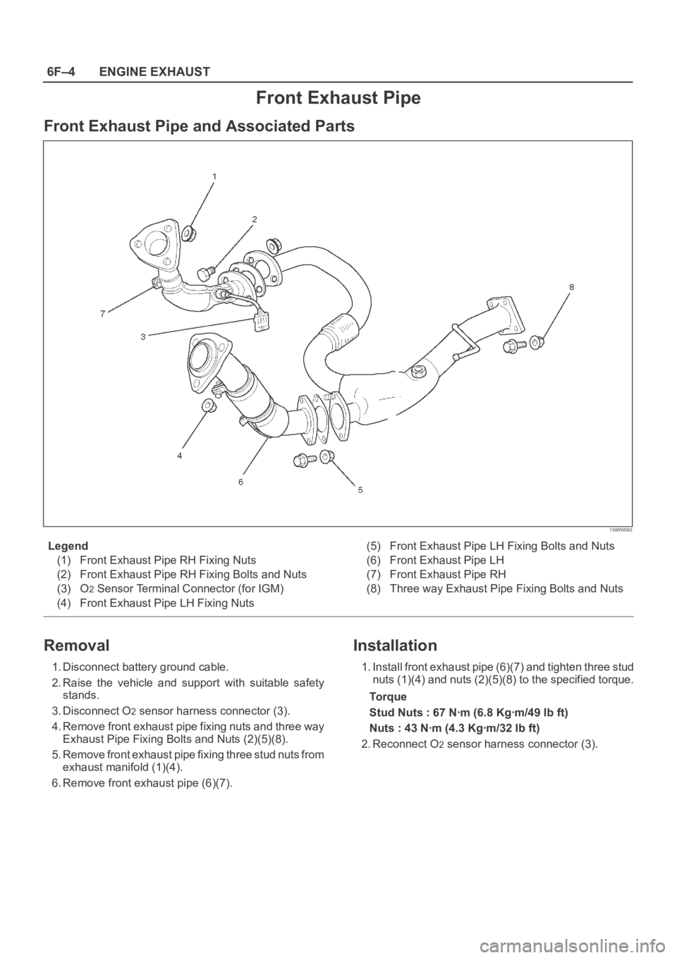
Front Exhaust Pipe and Associated Parts
150RW063
Legend
(1) Front Exhaust Pipe RH Fixing Nuts
(2) Front Exhaust Pipe RH Fixing Bolts and Nuts
(3) O
2 Sensor Terminal Connector (for IGM)
(4) Front Exhaust Pipe LH Fixing Nuts(5) Front Exhaust Pipe LH Fixing Bolts and Nuts
(6) Front Exhaust Pipe LH
(7) Front Exhaust Pipe RH
(8) Three way Exhaust Pipe Fixing Bolts and Nuts
Removal
1. Disconnect battery ground cable.
2. Raise the vehicle and support with suitable safety
stands.
3. Disconnect O
2 sensor harness connector (3).
4. Remove front exhaust pipe fixing nuts and three way
Exhaust Pipe Fixing Bolts and Nuts (2)(5)(8).
5. Remove front exhaust pipe fixing three stud nuts from
exhaust manifold (1)(4).
6. Remove front exhaust pipe (6)(7).
Installation
1. Install front exhaust pipe (6)(7) and tighten three stud
nuts (1)(4) and nuts (2)(5)(8) to the specified torque.
To r q u e
Stud Nuts : 67 Nꞏm (6.8 Kgꞏm/49 lb ft)
Nuts : 43 Nꞏm (4.3 Kgꞏm/32 lb ft)
2. Reconnect O
2 sensor harness connector (3).
Page 5040 of 6000
6J–2
INDUCTION
Air Cleaner Element
Removal
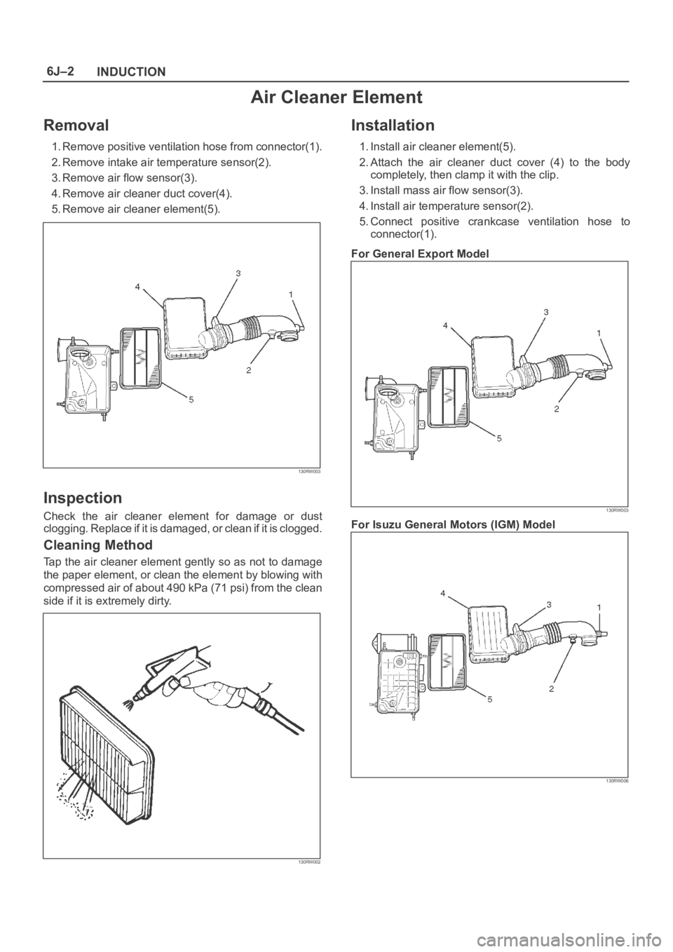
1. Remove positive ventilation hose from connector(1).
2. Remove intake air temperature sensor(2).
3. Remove air flow sensor(3).
4. Remove air cleaner duct cover(4).
5. Remove air cleaner element(5).
130RW003
Inspection
Check the air cleaner element for damage or dust
clogging. Replace if it is damaged, or clean if it is clogged.
Cleaning Method
Tap the air cleaner element gently so as not to damage
the paper element, or clean the element by blowing with
compressed air of about 490 kPa (71 psi) from the clean
side if it is extremely dirty.
130RW002
Installation
1. Install air cleaner element(5).
2. Attach the air cleaner duct cover (4) to the body
completely, then clamp it with the clip.
3. Install mass air flow sensor(3).
4. Install air temperature sensor(2).
5. Connect positive crankcase ventilation hose to
connector(1).
For General Export Model
130RW003
For Isuzu General Motors (IGM) Model
130RW006
Page 5286 of 6000
ENGINE MECHANICAL 6A – 13
VALVE CLEARANCE ADJUSTMENT
1. Install 2.80 mm valve adjuster (shim) first when
reassembling the engine.
Thickness mark faces down.
2. Measure the valve clearance after installing cam
carrier assy with camshafts.
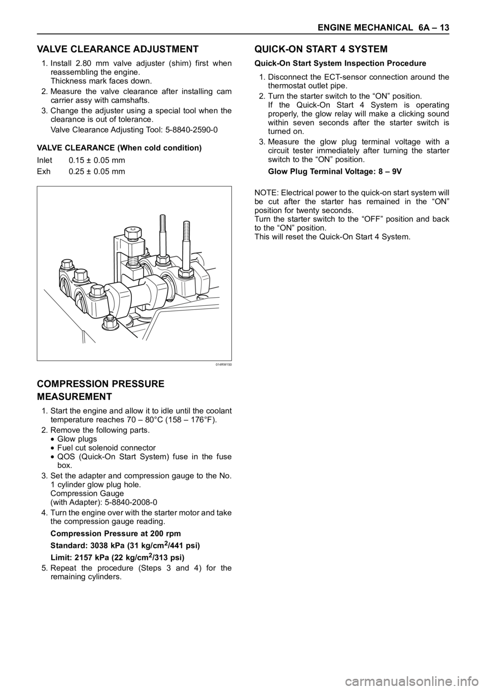
3. Change the adjuster using a special tool when the
clearance is out of tolerance.
Valve Clearance Adjusting Tool: 5-8840-2590-0
VALVE CLEARANCE (When cold condition)
Inlet 0.15 ± 0.05 mm
Exh 0.25 ± 0.05 mm
COMPRESSION PRESSURE
MEASUREMENT
1. Start the engine and allow it to idle until the coolant
temperature reaches 70 – 80°C (158 – 176°F).
2. Remove the following parts.
Glow plugs
Fuel cut solenoid connector
QOS (Quick-On Start System) fuse in the fuse
box.
3. Set the adapter and compression gauge to the No.
1 cylinder glow plug hole.
Compression Gauge
(with Adapter): 5-8840-2008-0
4. Turn the engine over with the starter motor and take
the compression gauge reading.
Compression Pressure at 200 rpm
Standard: 3038 kPa (31 kg/cm
2/441 psi)
Limit: 2157 kPa (22 kg/cm
2/313 psi)
5. Repeat the procedure (Steps 3 and 4) for the
remaining cylinders.
QUICK-ON START 4 SYSTEM
Quick-On Start System Inspection Procedure
1. Disconnect the ECT-sensor connection around the
thermostat outlet pipe.
2. Turn the starter switch to the “ON” position.
If the Quick-On Start 4 System is operating
properly, the glow relay will make a clicking sound
within seven seconds after the starter switch is
turned on.
3. Measure the glow plug terminal voltage with a
circuit tester immediately after turning the starter
switch to the “ON” position.
Glow Plug Terminal Voltage: 8 – 9V
NOTE: Electrical power to the quick-on start system will
be cut after the starter has remained in the “ON”
position for twenty seconds.
Turn the starter switch to the “OFF” position and back
to the “ON” position.
This will reset the Quick-On Start 4 System.
014RW150
Page 5306 of 6000
ENGINE MECHANICAL 6A – 33
INTAKE MANIFOLD
REMOVAL
1. Drain engine coolant and disconnect water hose
from thermostat hosing.
2. Remove intercooler assembly
Refer to “Intercooler” in this manual.
3. Remove bracket bolt of oil level gauge guide tube.
4. Remove PCV Hose.
5. Remove hoses from EGR, EGR vacuum sensor
and inlet/outlet of heater.
6. Disconnect harness connector form MAP sensor,
EGR vacuum sensor, ETC sensor, water
temperature unit, IAT sensor and EVRV.
7. Remove high pressure oil pipe.
8. Remove the two way valve.
9. Remove fuel pipe from between intake manifold
and high pressure oil pump.
10. Remove fixing bolts and nuts on the intake
manifold, then remove the intake manifold
assembly.
INSTALLATION
1. Install the intake manifold, tighten bolts and nuts to
the specified torque.
Torque : 20 Nꞏm (2.0 kgꞏm/14.5 lb ft) for bolt and nut
2. Install the fuel pipe and tighten to the specified
torque.To r q u e :
M16 bolt (apply engine oil) 4 Nꞏm (0.4 kgꞏm/2.9
lb ft)
Cap nut (M10) 13Nꞏm (1.3 kgꞏm/9.4 lb ft)
Fuel pipe (M10 apply engine oil) 14 Nꞏm (1.4
kgꞏm/10 lb ft)
3. Install two way valve.
Torque : 20 Nꞏm (2.0 kgꞏm/14.5 lb ft)
4. Fill with about 300 cc of engine oil from the high
pressure oil pipe installation port of the oil rail using
an oil filler. If assembled without filling the oil rail
with oil, the time for starting the engine will be
longer.
5. Install the high pressure oil pipe immediately and
tighten the sleeve nut to the specified torque.
Torque : 80 Nꞏm (8 kgꞏm/57.9 lb ft)
6. Reconnect harness connector to MAP sensor, EGR
vacuum sensor, ETC sensor, Water temperature
unit, IAT sensor and EVRV.
7. Connect the hoses to EGR valve, EGR vacuum
sensor, and water inlet/outlet pipe for heater.
8. Connect PCV hose.
9. Install the oil level gauge guide tube and tighten
bracket bolt.
10. Install the intercooler assembly.
Refer to “Intercooler” in this manual.
11. Connect the hose to the thermostat housing and fill
with engine coolant.
2
3
4
1
025RX001
Legend
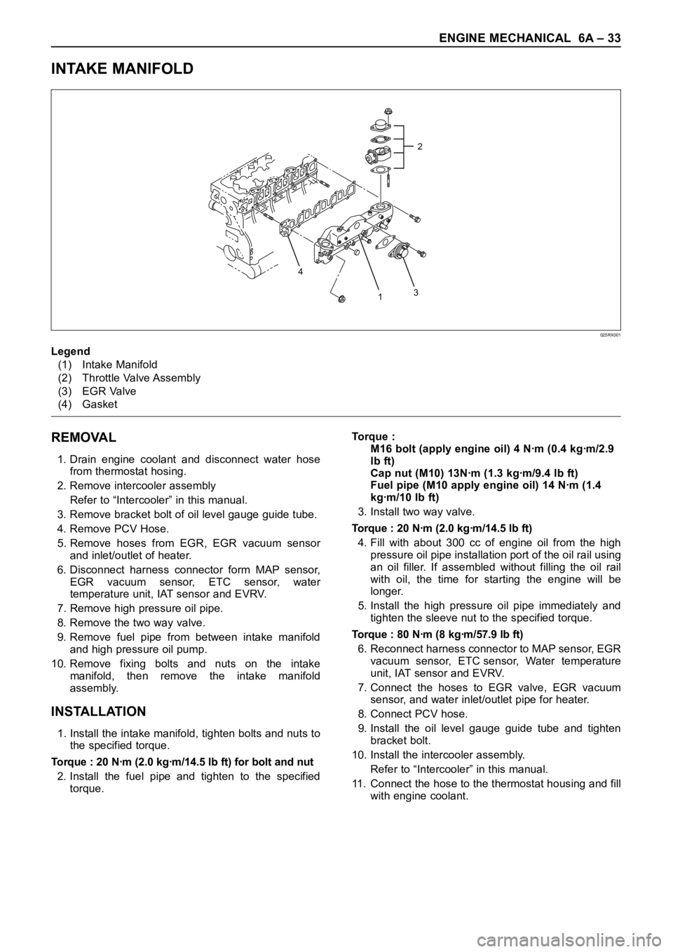
(1) Intake Manifold
(2) Throttle Valve Assembly
(3) EGR Valve
(4) Gasket
Page 5313 of 6000
6A – 40 ENGINE MECHANICAL
REMOVAL
1. Disconnect battery ground cable.
2. Drain engine coolant.
3. Remove air cleaner and air duct.
4. Remove intercooler assembly.
Refer to “Intercooler” in this manual.
5. Remove oil level gauge guide assembly.
6. Remove PCV hose.
7. Remove EGR vacuum hose.
8. Disconnect harness connector around the cylinder
head.
9. Remove A/C compressor assembly.
10. Remove A/C compressor bracket.
11. Remove generator assembly and take out fan belt.
12. Remove heat protector and remove valve
assembly.
13. Remove water hose and oil pipe from turbocharger.
14. Remove turbocharger assembly.
15. Remove water hose between thermostat and
radiator.
16. Remove cylinder head noise insulator cover.
NOTE: Do not make damage to the harness.
17. Remove high pressure pipe.
18. Remove timing belt cover.
19. Remove CMP sensor bracket.
20. Remove timing belt tensioner and remove timing
belt.
21. Remove camshaft pulley.
22. Remove front plate.
23. Remove water pipe between cylinder head and
water pump.
24. Remove fuel pipe between fuel pump and intake
manifold.
25. Remove fuel return pipe.
26. Remove intake manifold assembly.
27. Disconnect glow plug wiring and remove glow plug.
28. Remove cylinder head cover.
29. Drain oil from oil rail.
30. Disconnect injector harness connector.
31. Disconnect harness connector from oil pressure
sensor and oil temperature sensor on the oil rail.
32. Disconnect injector harness assembly.
33. Remove injector clamp.
34. Remove injector spacer.
35. Remove injector assembly.
36. Remove oil rail assembly.
37. Remove camshaft carrier.
38. Remove cylinder head assembly.
39. Remove cylinder gasket.
INSTALLATION
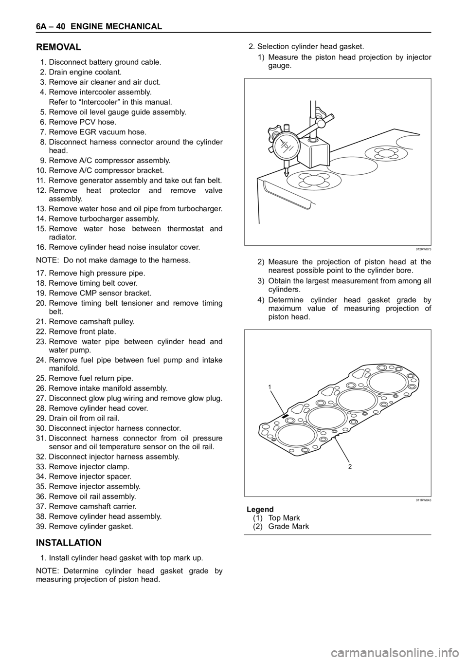
1. Install cylinder head gasket with top mark up.
NOTE: Determine cylinder head gasket grade by
measuring projection of piston head.2. Selection cylinder head gasket.
1) Measure the piston head projection by injector
gauge.
2) Measure the projection of piston head at the
nearest possible point to the cylinder bore.
3) Obtain the largest measurement from among all
cylinders.
4) Determine cylinder head gasket grade by
maximum value of measuring projection of
piston head.
Legend
(1) Top Mark
(2) Grade Mark
012RW073
2 1
011RW043
Page 5314 of 6000

ENGINE MECHANICAL 6A – 41
Cylinder head gasket and piston projection mm
CAUTION:
The projection of each piston should be 0.333
mm or more and less than 0.483 mm.
Maximum difference in projection between
pistons should be less than 0.1 mm.
If the piston projection is without standard,
reassemble the engine all over again.
3. Install cylinder head assembly, tighten bolts by
angular tightening method.
To r q u e :
1st step; 49 Nꞏm (4.9 kgꞏm/35.4 lb ft)
2nd step; 60°
3rd step; 60°
4. Install camshaft carrier assembly.
Refer to “Camshaft” in this manual.
5. Install oil rail and injector assembly.
Refer to “Oil rail and injector” in this manual.
6. Install injector harness to connect harness
connector.
Note: Apply liquid gasket (TB 1207B or equivalent) to
the rubber seal of the camshaft end, injector harness
gasket area and No. 1 camshaft bracket. Refer to the
Cylinder head cover.
7. Install cylinder head cover.
Torque: 9 Nꞏm (0.9 kgꞏm/6.5 lb ft)
8. Install glow plug to tighten specified torque.
Torque: 15 Nꞏm (1.5 kgꞏm/11 lb ft) and connect
glow plug harness.
9. Install intake manifold.Torque: 20 Nꞏm (2.0 kgꞏm/14.5 lb ft)
10. Install fuel return pipe.
11. Install fuel pipe in between fuel pump and intake
manifold.
12. Install water pipe in between cylinder head and
water pump.
Tighten flange bolt to the specified torque.
Torque: 20 Nꞏm (2.0 kgꞏm/14.5 lb ft)
13. Install front plate.
Torque: 20 Nꞏm (2.0 kgꞏm/14.5 lb ft)
14. Install camshaft pulley, tighten with angular
tightening method.
1st step 40 Nꞏm (4.0 kgꞏm/29 lb ft)
2nd step 60°
NOTE: Apply engine oil to camshaft pulley bolt.
15. Align timing mark oil pump pulley and camshaft
pulley to front plate then put the timing belt and
tighten tensioner bolt.
Torque: 20 Nꞏm (2.0 kgꞏm/14.5 lb ft) for M8
50 Nꞏm (5.1 kgꞏm/37 lb ft)
16. Install CMP sensor bracket.
17. Install timing belt cover.
Torque: 9 Nꞏm (0.9 kgꞏm/6.5 lb ft)
18. Fill with about 300 cc of engine oil from the high
pressure oil pipe installing port of oil rail using an oil
filler.
If assembled without filling the oil rail with oil, the
time for engine start will be longer.
19. Immediately install high pressure oil pipe to tighten
with specified torque.
Torque: 80 Nꞏm (8 kgꞏm/57.9 lb ft)
20. Install cylinder head noise insulator cover.
Torque: 9 Nꞏm (0.9 kgꞏm/6.5 lb ft)
Grade A Grade B Grade C
011RW042
Grade Piston projectionGasket
thickness
A more 0.333 to less 0.383 1.35
B more 0.383 to less 0.433 1.40
C more 0.433 to less 0.483 1.45