1998 OPEL FRONTERA belt
[x] Cancel search: beltPage 2084 of 6000
6E–191 4JX1–TC ENGINE DRIVEABILITY AND EMISSIONS
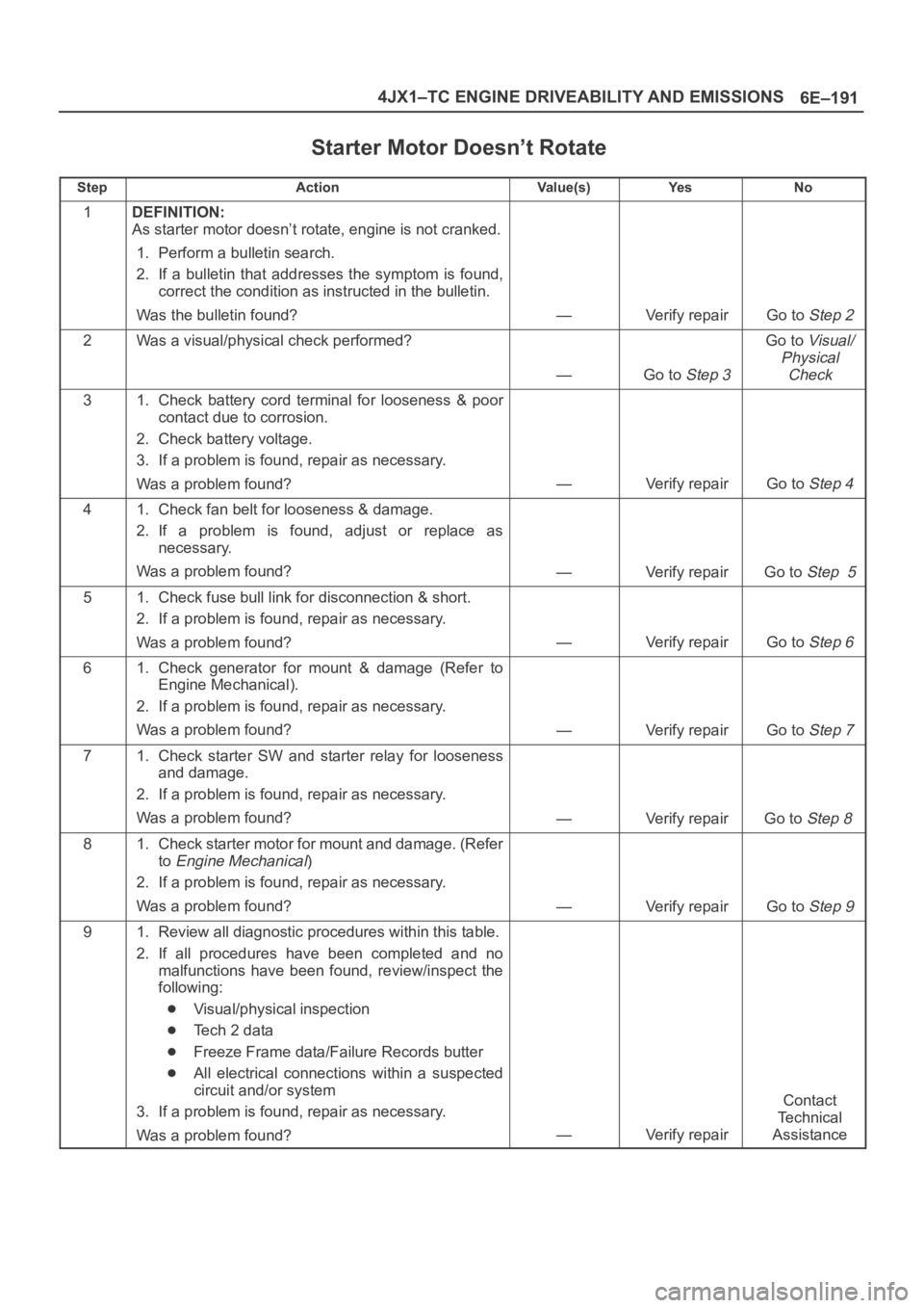
Starter Motor Doesn’t Rotate
StepActionVa l u e ( s )Ye sNo
1DEFINITION:
As starter motor doesn’t rotate, engine is not cranked.
1. Perform a bulletin search.
2. If a bulletin that addresses the symptom is found,
correct the condition as instructed in the bulletin.
Was the bulletin found?
—Verify repairGo to Step 2
2Was a visual/physical check performed?
—Go to Step 3
Go to Visual/
Physical
Check
31. Check battery cord terminal for looseness & poor
contact due to corrosion.
2. Check battery voltage.
3. If a problem is found, repair as necessary.
Was a problem found?
—Verify repairGo to Step 4
41. Check fan belt for looseness & damage.
2. If a problem is found, adjust or replace as
necessary.
Was a problem found?
—Verify repairGo to Step 5
51. Check fuse bull link for disconnection & short.
2. If a problem is found, repair as necessary.
Was a problem found?
—Verify repairGo to Step 6
61. Check generator for mount & damage (Refer to
Engine Mechanical).
2. If a problem is found, repair as necessary.
Was a problem found?
—Verify repairGo to Step 7
71. Check starter SW and starter relay for looseness
and damage.
2. If a problem is found, repair as necessary.
Was a problem found?
—Verify repairGo to Step 8
81. Check starter motor for mount and damage. (Refer
to
Engine Mechanical)
2. If a problem is found, repair as necessary.
Was a problem found?
—Verify repairGo to Step 9
91. Review all diagnostic procedures within this table.
2. If all procedures have been completed and no
malfunctions have been found, review/inspect the
following:
Visual/physical inspection
Te c h 2 d a t a
Freeze Frame data/Failure Records butter
All electrical connections within a suspected
circuit and/or system
3. If a problem is found, repair as necessary.
Was a problem found?
—Verify repair
Contact
Te c h n i c a l
Assistance
Page 2272 of 6000
TRANSMISSION CONTROL SYSTEM (4L30–E)7A1–27
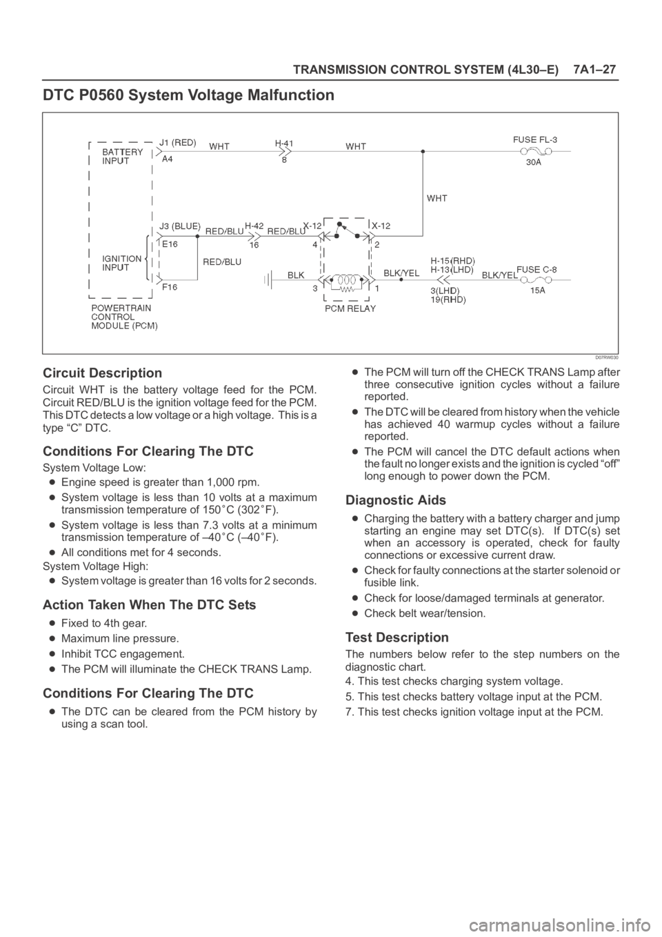
DTC P0560 System Voltage Malfunction
D07RW030
Circuit Description
Circuit WHT is the battery voltage feed for the PCM.
Circuit RED/BLU is the ignition voltage feed for the PCM.
This DTC detects a low voltage or a high voltage. This is a
type “C” DTC.
Conditions For Clearing The DTC
System Voltage Low:
Engine speed is greater than 1,000 rpm.
System voltage is less than 10 volts at a maximum
transmission temperature of 150
C (302F).
System voltage is less than 7.3 volts at a minimum
transmission temperature of –40
C (–40F).
All conditions met for 4 seconds.
System Voltage High:
System voltage is greater than 16 volts for 2 seconds.
Action Taken When The DTC Sets
Fixed to 4th gear.
Maximum line pressure.
Inhibit TCC engagement.
The PCM will illuminate the CHECK TRANS Lamp.
Conditions For Clearing The DTC
The DTC can be cleared from the PCM history by
using a scan tool.
The PCM will turn off the CHECK TRANS Lamp after
three consecutive ignition cycles without a failure
reported.
The DTC will be cleared from history when the vehicle
has achieved 40 warmup cycles without a failure
reported.
The PCM will cancel the DTC default actions when
the fault no longer exists and the ignition is cycled “off”
long enough to power down the PCM.
Diagnostic Aids
Charging the battery with a battery charger and jump
starting an engine may set DTC(s). If DTC(s) set
when an accessory is operated, check for faulty
connections or excessive current draw.
Check for faulty connections at the starter solenoid or
fusible link.
Check for loose/damaged terminals at generator.
Check belt wear/tension.
Test Description
The numbers below refer to the step numbers on the
diagnostic chart.
4. This test checks charging system voltage.
5. This test checks battery voltage input at the PCM.
7. This test checks ignition voltage input at the PCM.
Page 2568 of 6000
LIGHTING SYSTEM8A–29
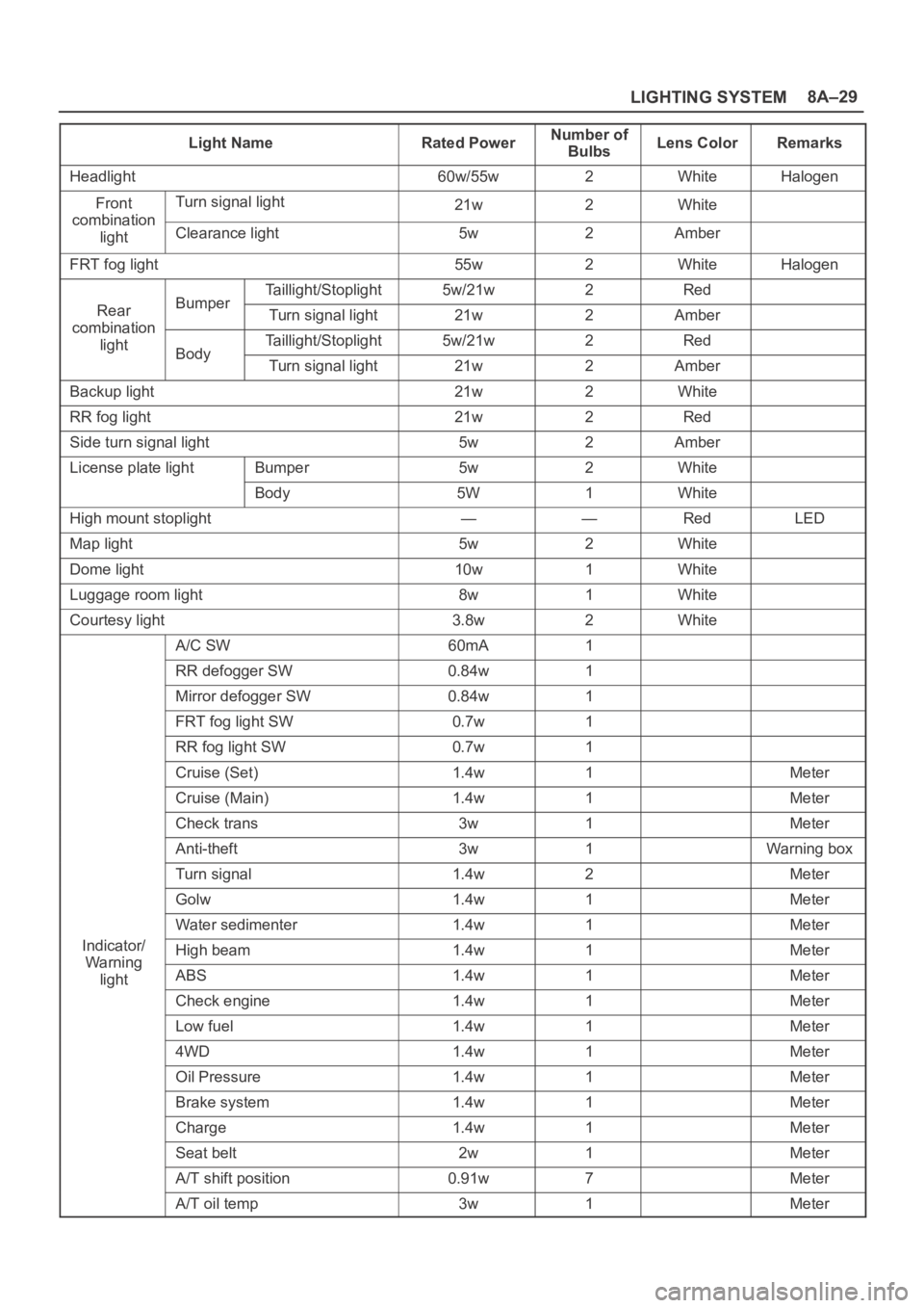
Light NameRated PowerNumber of
BulbsLens ColorRemarks
Headlight60w/55w2WhiteHalogen
FrontTurn signal light21w2Whitecombination
lightClearance light5w2Amber
FRT fog light55w2WhiteHalogen
Taillight/Stoplight5w/21w2Red
RearBumperTurn signal light21w2Ambercombination
lightTaillight/Stoplight5w/21w2RedBodyTurn signal light21w2Amber
Backup light21w2White
RR fog light21w2Red
Side turn signal light5w2Amber
License plate lightBumper5w2White
Body5W1White
High mount stoplight——RedLED
Map light5w2White
Dome light10w1White
Luggage room light8w1White
Courtesy light3.8w2White
A/C SW60mA1
RR defogger SW0.84w1
Mirror defogger SW0.84w1
FRT fog light SW0.7w1
RR fog light SW0.7w1
Cruise (Set)1.4w1Meter
Cruise (Main)1.4w1Meter
Check trans3w1Meter
Anti-theft3w1Warning box
Turn signal1.4w2Meter
Golw1.4w1Meter
Water sedimenter1.4w1Meter
Indicator/High beam1.4w1MeterWa rnin g
lightABS1.4w1Meter
Check engine1.4w1Meter
Low fuel1.4w1Meter
4WD1.4w1Meter
Oil Pressure1.4w1Meter
Brake system1.4w1Meter
Charge1.4w1Meter
Seat belt2w1Meter
A/T shift position0.91w7Meter
A/T oil temp3w1Meter
Page 3026 of 6000
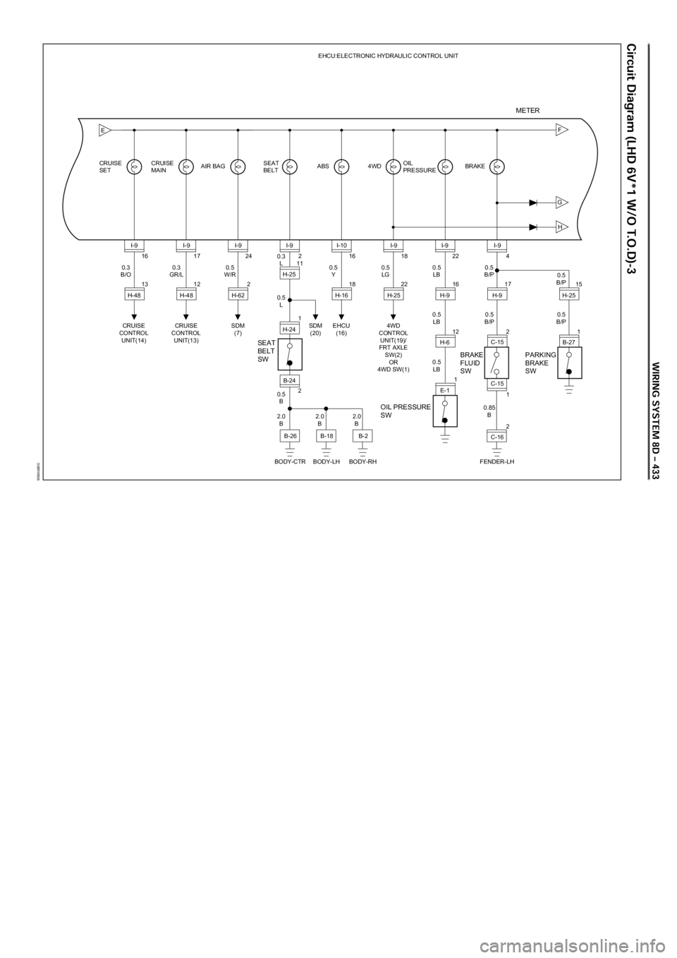
D08RW926
G
H
FE
16
13 CRUISE
SETCRUISE
MAINAIR BAG ABS 4WD BRAKEEHCU:ELECTRONIC HYDRAULIC CONTROL UNIT
OIL
PRESSURE
CRUISE
CONTROL
UNIT(14)0.3
B/OI-9
H-4817
12
CRUISE
CONTROL
UNIT(13) 0.3
GR/LI-9
H-4824
2
SDM
(7)SDM
(20) 0.5
W/RI-9
H-6216
18
EHCU
(16)
OIL PRESSURE
SWBRAKE
FLUID
SW SEAT
BELT
SWPARKING
BRAKE
SW
0.5
YI-10
H-1618
22
4WD
CONTROL
UNIT(19)/
FRT AXLE
SW(2)
OR
4WD SW(1)0.5
LGI-9
H-2522
16
12
1 0.5
LB
0.5
LB0.5
B/P
0.85
B0.5
B/P0.5
B/P
0.5
LBI-9
H-9
H-6
E-1
SEAT
BELT
2
11 0.3
L
0.5
L
2.0
B2.0
B2.0
B 0.5
BI-9
B-24 H-25
1
2 H-244
1
2 17
215
1
FENDER-LH0.5
B/PI-9
H-9
C-15
C-16
BODY-CTR BODY-LH BODY-RHB-26
B-18B-2C-15H-25
B-27
METER
Page 3032 of 6000
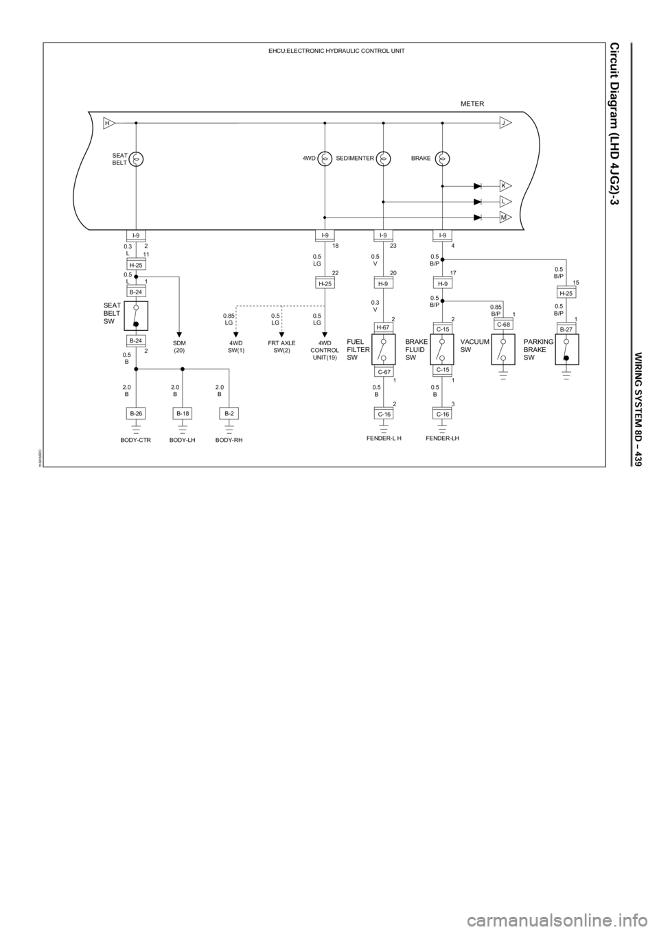
D08RW914
H
SEAT
BELT
SW
BODY-LH
B-18
BODY-CTRBODY-RH
B-2
2
11 0.3
L
0.5
L
2.0
B 2.0
B 2.0
B 0.5
BI-9
B-24 H-25
1
B-24
SEAT
BELT
B-262
BRAKE EHCU:ELECTRONIC HYDRAULIC CONTROL UNIT
SEDIMENTER 4WD
BRAKE
FLUID
SWPARKING
BRAKE
SW
18
22
4WD
CONTROL
UNIT(19)
FRT AXLE
SW(2)4WD
SW(1) SDM
(20)0.5
LG
0.5
LG 0.5
LG 0.85
LGI-9
H-2523
20
2 0.5
V
0.3
V0.5
B/P
0.85
B/P
0.5
B0.5
B/P0.5
B/P I-9
H-9
H-674
1
3 17
215
1
FENDER-LH0.5
B/PI-9
H-9
C-15
C-16 C-15FUEL
FILTER
SW
0.5
B1
2
FENDER-L HC-16 C-67
VACUUM
SW
1
C-68H-25
B-27
METER
Page 3140 of 6000
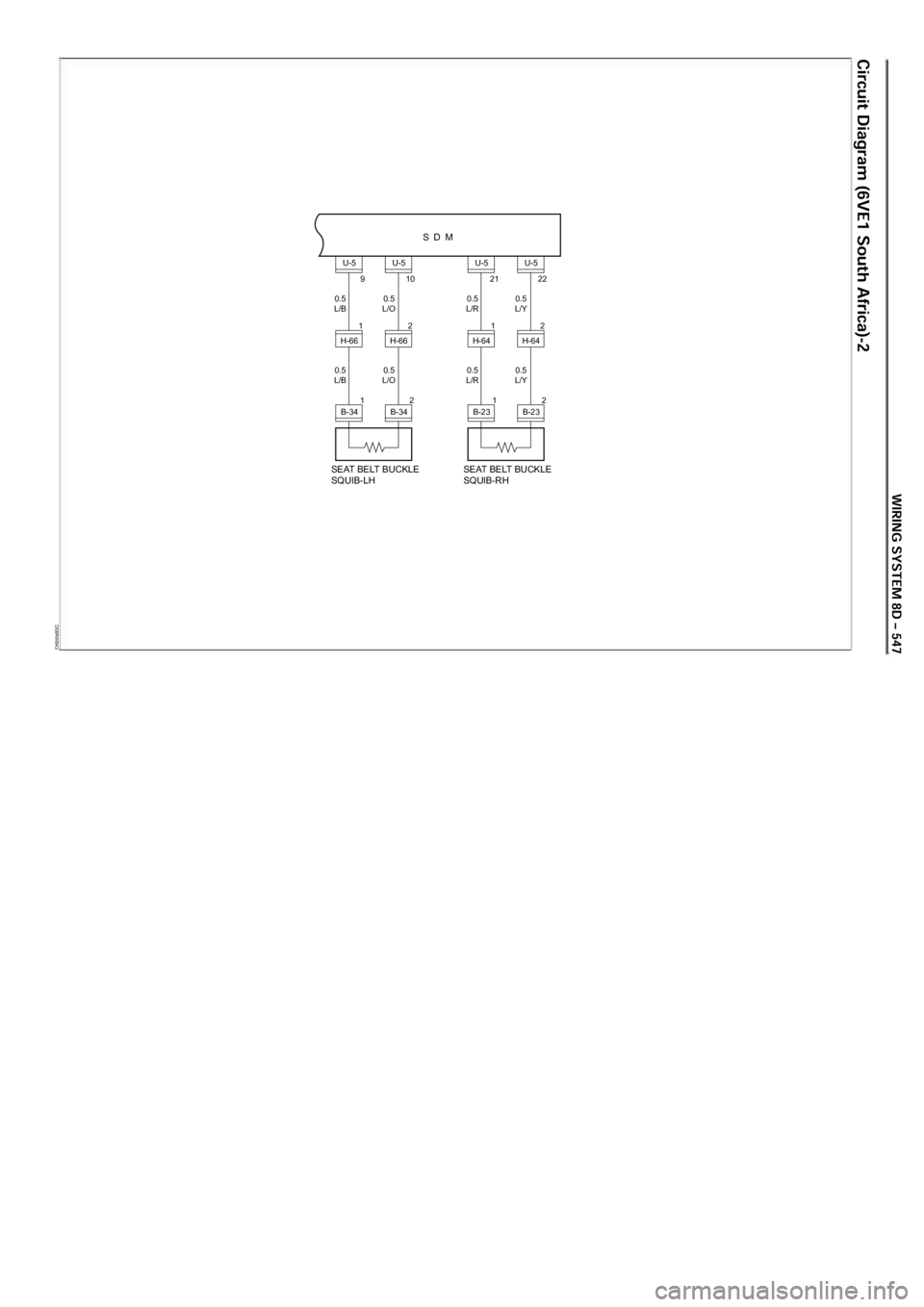
D08RWB43
SDM
0.5
L/B 0.5
L/O
0.5
L/B 0.5
L/O
9
U-5U-5
10
SEAT BELT BUCKLE
SQUIB-LH
B-34
H-66 2H-661
2
1
B-34
0.5
L/R 0.5
L/Y
0.5
L/R 0.5
L/Y
21
U-5U-5
22
SEAT BELT BUCKLE
SQUIB-RH
B-23
H-64 2H-64 1
2
1
B-23
Page 3178 of 6000
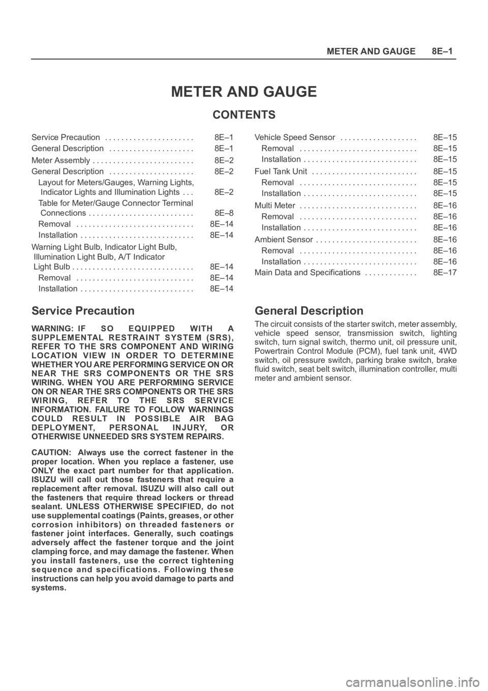
METER AND GAUGE8E–1
METER AND GAUGE
CONTENTS
Service Precaution 8E–1. . . . . . . . . . . . . . . . . . . . . .
General Description 8E–1. . . . . . . . . . . . . . . . . . . . .
Meter Assembly 8E–2. . . . . . . . . . . . . . . . . . . . . . . . .
General Description 8E–2. . . . . . . . . . . . . . . . . . . . .
Layout for Meters/Gauges, Warning Lights,
Indicator Lights and Illumination Lights 8E–2. . .
Table for Meter/Gauge Connector Terminal
Connections 8E–8. . . . . . . . . . . . . . . . . . . . . . . . . .
Removal 8E–14. . . . . . . . . . . . . . . . . . . . . . . . . . . . .
Installation 8E–14. . . . . . . . . . . . . . . . . . . . . . . . . . . .
Warning Light Bulb, Indicator Light Bulb,
Illumination Light Bulb, A/T Indicator
Light Bulb 8E–14. . . . . . . . . . . . . . . . . . . . . . . . . . . . . .
Removal 8E–14. . . . . . . . . . . . . . . . . . . . . . . . . . . . .
Installation 8E–14. . . . . . . . . . . . . . . . . . . . . . . . . . . . Vehicle Speed Sensor 8E–15. . . . . . . . . . . . . . . . . . .
Removal 8E–15. . . . . . . . . . . . . . . . . . . . . . . . . . . . .
Installation 8E–15. . . . . . . . . . . . . . . . . . . . . . . . . . . .
Fuel Tank Unit 8E–15. . . . . . . . . . . . . . . . . . . . . . . . . .
Removal 8E–15. . . . . . . . . . . . . . . . . . . . . . . . . . . . .
Installation 8E–15. . . . . . . . . . . . . . . . . . . . . . . . . . . .
Multi Meter 8E–16. . . . . . . . . . . . . . . . . . . . . . . . . . . . .
Removal 8E–16. . . . . . . . . . . . . . . . . . . . . . . . . . . . .
Installation 8E–16. . . . . . . . . . . . . . . . . . . . . . . . . . . .
Ambient Sensor 8E–16. . . . . . . . . . . . . . . . . . . . . . . . .
Removal 8E–16. . . . . . . . . . . . . . . . . . . . . . . . . . . . .
Installation 8E–16. . . . . . . . . . . . . . . . . . . . . . . . . . . .
Main Data and Specifications 8E–17. . . . . . . . . . . . .
Service Precaution
WARNING: IF SO EQUIPPED WITH A
SUPPLEMENTAL RESTRAINT SYSTEM (SRS),
REFER TO THE SRS COMPONENT AND WIRING
LOCATION VIEW IN ORDER TO DETERMINE
WHETHER YOU ARE PERFORMING SERVICE ON OR
NEAR THE SRS COMPONENTS OR THE SRS
WIRING. WHEN YOU ARE PERFORMING SERVICE
ON OR NEAR THE SRS COMPONENTS OR THE SRS
WIRING, REFER TO THE SRS SERVICE
INFORMATION. FAILURE TO FOLLOW WARNINGS
COULD RESULT IN POSSIBLE AIR BAG
DEPLOYMENT, PERSONAL INJURY, OR
OTHERWISE UNNEEDED SRS SYSTEM REPAIRS.
CAUTION: Always use the correct fastener in the
proper location. When you replace a fastener, use
ONLY the exact part number for that application.
ISUZU will call out those fasteners that require a
replacement after removal. ISUZU will also call out
the fasteners that require thread lockers or thread
sealant. UNLESS OTHERWISE SPECIFIED, do not
use supplemental coatings (Paints, greases, or other
corrosion inhibitors) on threaded fasteners or
fastener joint interfaces. Generally, such coatings
adversely affect the fastener torque and the joint
clamping force, and may damage the fastener. When
you install fasteners, use the correct tightening
sequence and specifications. Following these
instructions can help you avoid damage to parts and
systems.
General Description
The circuit consists of the starter switch, meter assembly,
vehicle speed sensor, transmission switch, lighting
switch, turn signal switch, thermo unit, oil pressure unit,
Powertrain Control Module (PCM), fuel tank unit, 4WD
switch, oil pressure switch, parking brake switch, brake
fluid switch, seat belt switch, illumination controller, multi
meter and ambient sensor.
Page 3186 of 6000
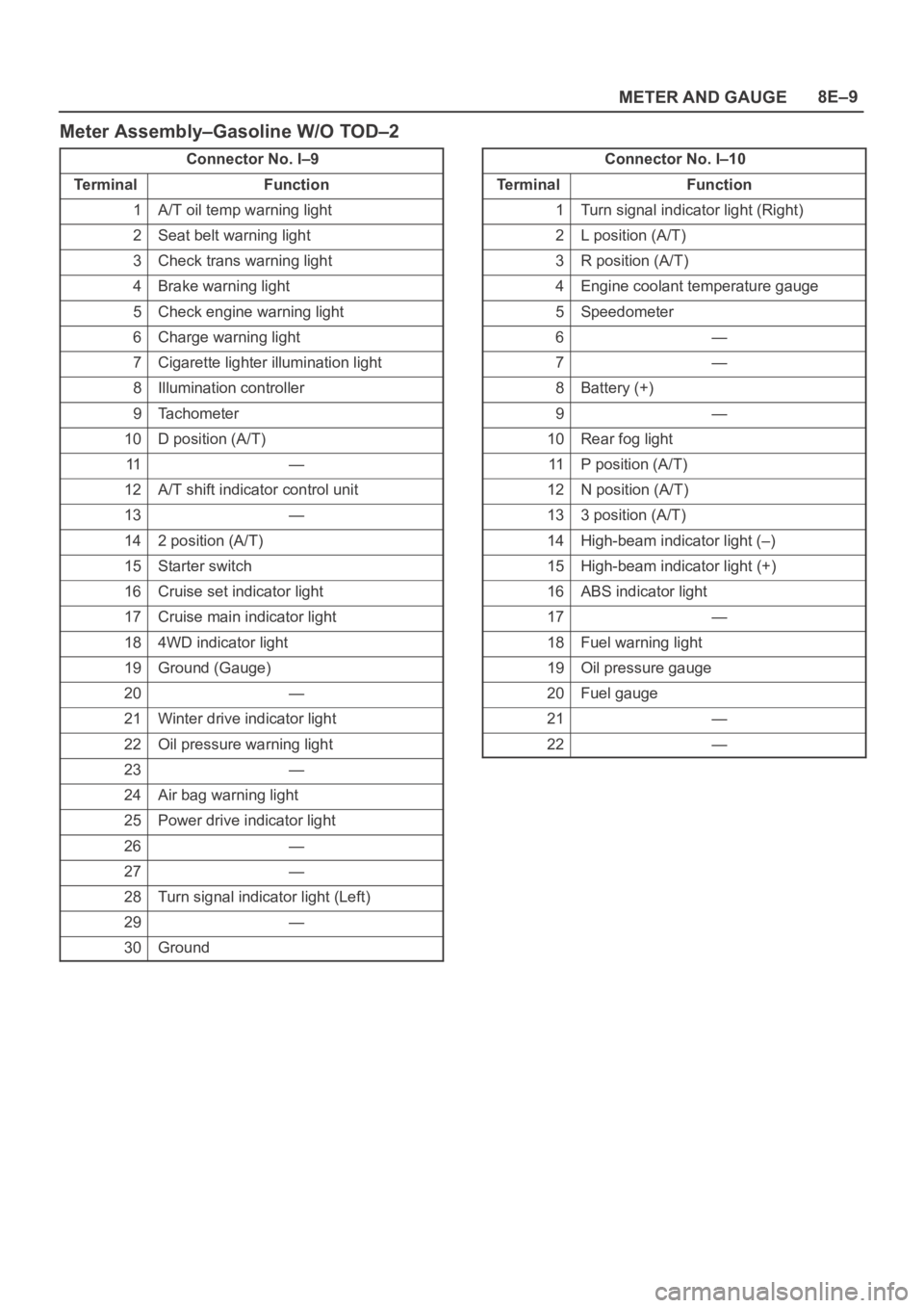
METER AND GAUGE8E–9
Meter Assembly–Gasoline W/O TOD–2
Connector No. I–9
Te r m i n a lFunction
1A/T oil temp warning light
2Seat belt warning light
3Check trans warning light
4Brake warning light
5Check engine warning light
6Charge warning light
7Cigarette lighter illumination light
8Illumination controller
9Tachometer
10D position (A/T)
11—
12A/T shift indicator control unit
13—
142 position (A/T)
15Starter switch
16Cruise set indicator light
17Cruise main indicator light
184WD indicator light
19Ground (Gauge)
20—
21Winter drive indicator light
22Oil pressure warning light
23—
24Air bag warning light
25Power drive indicator light
26—
27—
28Turn signal indicator light (Left)
29—
30Ground
Connector No. I–10
Te r m i n a lFunction
1Turn signal indicator light (Right)
2L position (A/T)
3R position (A/T)
4Engine coolant temperature gauge
5Speedometer
6—
7—
8Battery (+)
9—
10Rear fog light
11P position (A/T)
12N position (A/T)
133 position (A/T)
14High-beam indicator light (–)
15High-beam indicator light (+)
16ABS indicator light
17—
18Fuel warning light
19Oil pressure gauge
20Fuel gauge
21—
22—