Page 1398 of 6000

6E–281 ENGINE DRIVEABILITY AND EMISSIONS
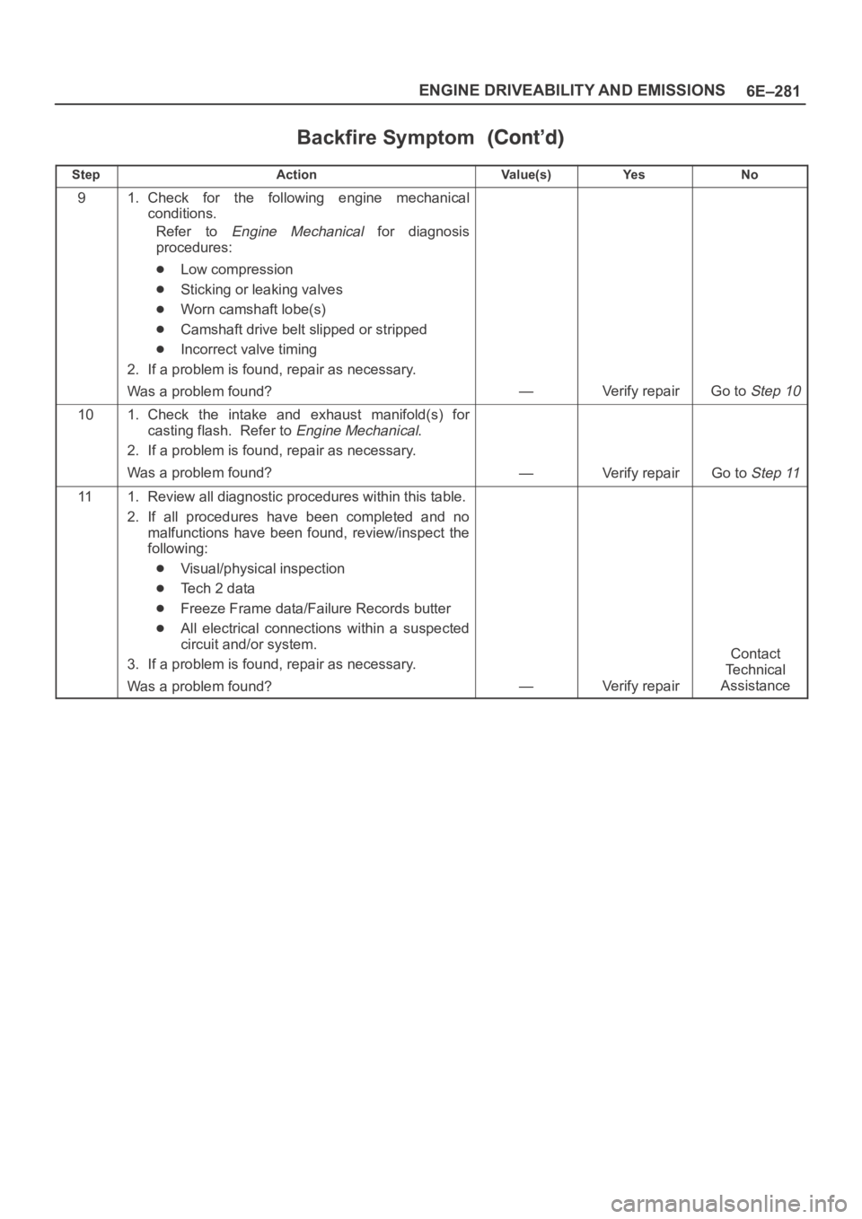
Backfire Symptom
StepNo Ye s Va l u e ( s ) Action
91. Check for the following engine mechanical
conditions.
Refer to
Engine Mechanical for diagnosis
procedures:
Low compression
Sticking or leaking valves
Worn camshaft lobe(s)
Camshaft drive belt slipped or stripped
Incorrect valve timing
2. If a problem is found, repair as necessary.
Was a problem found?
—Verify repairGo to Step 10
101. Check the intake and exhaust manifold(s) for
casting flash. Refer to
Engine Mechanical.
2. If a problem is found, repair as necessary.
Was a problem found?
—Verify repairGo to Step 11
111. Review all diagnostic procedures within this table.
2. If all procedures have been completed and no
malfunctions have been found, review/inspect the
following:
Visual/physical inspection
Te c h 2 d a t a
Freeze Frame data/Failure Records butter
All electrical connections within a suspected
circuit and/or system.
3. If a problem is found, repair as necessary.
Was a problem found?
—Verify repair
Contact
Te c h n i c a l
Assistance
Page 1401 of 6000

6E–284
ENGINE DRIVEABILITY AND EMISSIONS
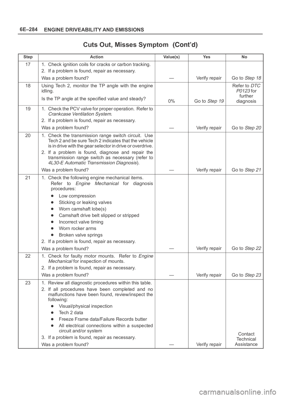
Cuts Out, Misses Symptom
StepNo Ye s Va l u e ( s ) Action
171. Check ignition coils for cracks or carbon tracking.
2. If a problem is found, repair as necessary.
Was a problem found?
—Verify repairGo to Step 18
18Using Tech 2, monitor the TP angle with the engine
idling.
Is the TP angle at the specified value and steady?
0%Go to Step 19
Refer to DTC
P0123
for
further
diagnosis
191. Check the PCV valve for proper operation. Refer to
Crankcase Ventilation System.
2. If a problem is found, repair as necessary.
Was a problem found?
—Verify repairGo to Step 20
201. Check the transmission range switch circuit. Use
Tech 2 and be sure Tech 2 indicates that the vehicle
is in drive with the gear selector in drive or overdrive.
2. If a problem is found, diagnose and repair the
transmission range switch as necessary (refer to
4L30-E Automatic Transmission Diagnosis).
Was a problem found?
—Verify repairGo to Step 21
211. Check the following engine mechanical items.
Refer to
Engine Mechanical for diagnosis
procedures:
Low compression
Sticking or leaking valves
Worn camshaft lobe(s)
Camshaft drive belt slipped or stripped
Incorrect valve timing
Worn rocker arms
Broken valve springs
2. If a problem is found, repair as necessary.
Was a problem found?
—Verify repairGo to Step 22
221. Check for faulty motor mounts. Refer to Engine
Mechanical
for inspection of mounts.
2. If a problem is found, repair as necessary.
Was a problem found?
—Verify repairGo to Step 23
231. Review all diagnostic procedures within this table.
2. If all procedures have been completed and no
malfunctions have been found, review/inspect the
following:
Visual/physical inspection
Te c h 2 d a t a
Freeze Frame data/Failure Records butter
All electrical connections within a suspected
circuit and/or system
3. If a problem is found, repair as necessary.
Was a problem found?
—Verify repair
Contact
Te c h n i c a l
Assistance
Page 1489 of 6000

6G–10
ENGINE LUBRICATION
Oil Pump
Removal
1. Disconnect battery ground cable.
2. Drain engine oil.
3. Remove crankcase assembly.
Refer to removal procedure for Oil Pan and
Crankcase in this manual.
4. Remove crankshaft pulley.
Refer to removal procedure for Crankshaft Pulley in
this manual.
5. Remove timing belt.
Refer to removal procedure for Timing Belt in this
manual.
6. Remove timing pulley from crankshaft.
7. Remove four fixing bolts from oil filter assembly.
8. Remove oil strainer fixing bolts, remove oil strainer
assembly with O-ring.
9. Remove three bolts from oil pipe and O-ring.
10. Remove eight oil pump fixing bolts, then oil pump
assembly.
11. Remove sealant from mounting surface of oil pump
assembly, cylinder block and take care not to damage
mounting surfaces of oil pump and cylinder block.
Installation
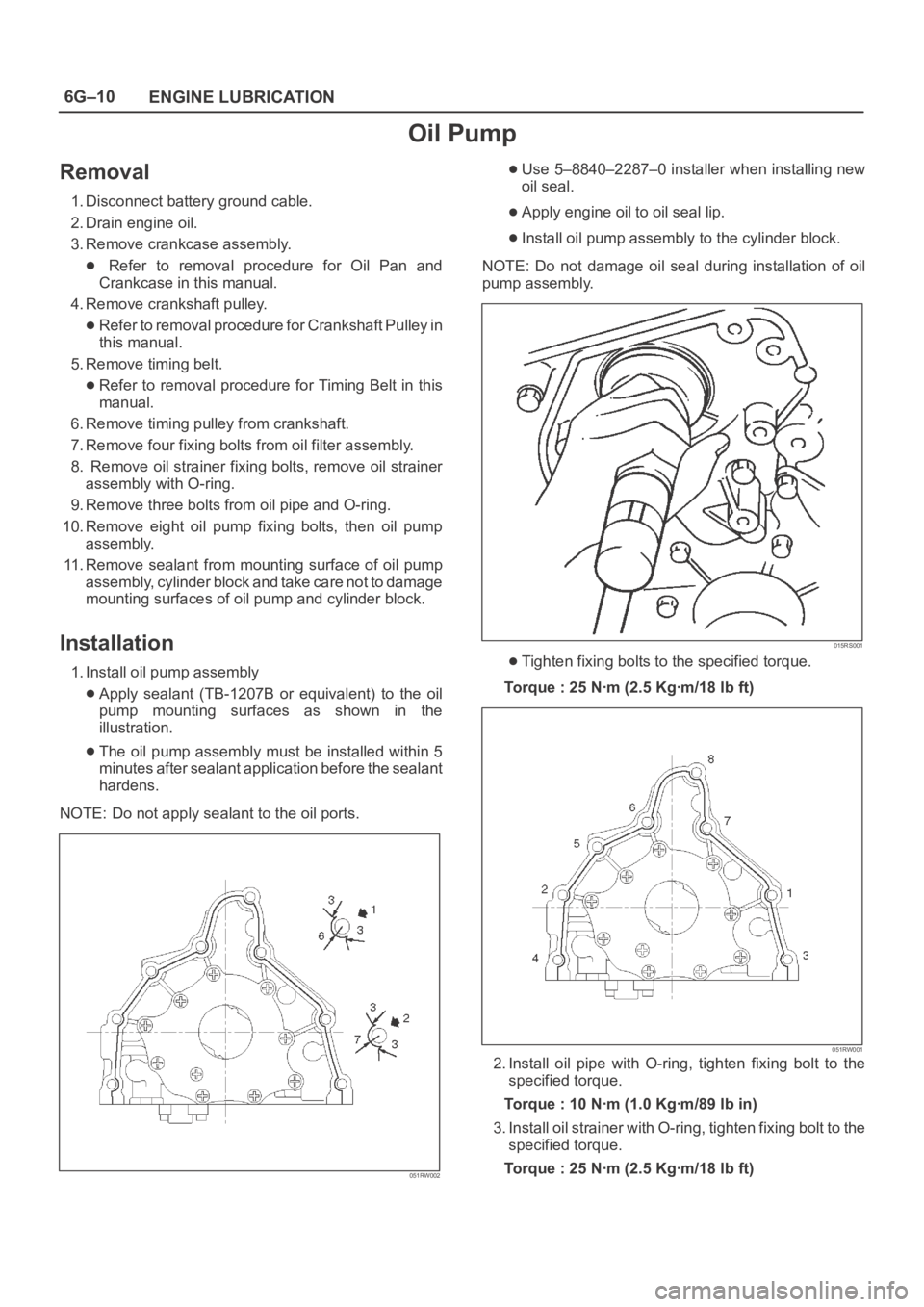
1. Install oil pump assembly
Apply sealant (TB-1207B or equivalent) to the oil
pump mounting surfaces as shown in the
illustration.
The oil pump assembly must be installed within 5
minutes after sealant application before the sealant
hardens.
NOTE: Do not apply sealant to the oil ports.
051RW002
Use 5–8840–2287–0 installer when installing new
oil seal.
Apply engine oil to oil seal lip.
Install oil pump assembly to the cylinder block.
NOTE: Do not damage oil seal during installation of oil
pump assembly.
015RS001
Tighten fixing bolts to the specified torque.
Torque : 25 Nꞏm (2.5 Kgꞏm/18 lb ft)
051RW001
2. Install oil pipe with O-ring, tighten fixing bolt to the
specified torque.
Torque : 10 Nꞏm (1.0 Kgꞏm/89 lb in)
3. Install oil strainer with O-ring, tighten fixing bolt to the
specified torque.
Torque : 25 Nꞏm (2.5 Kgꞏm/18 lb ft)
Page 1490 of 6000
6G–11 ENGINE LUBRICATION
4. Install oil filter assembly and tighten bolts to the
specified torque.
Torque : 25 Nꞏm (2.5 Kgꞏm/18 lb ft)
050RW001
Legend
(1) Oil Pump
(2) Oil Filter
(3) Oil Gallery
(4) From Oil Filter
(5) To Oil Filter
5. Install timing pulley on crankshaft.
Install timing belt.
Refer to installation procedure for Timing Belt in this
manual.
6. Install crankshaft pulley.
Refer to install procedure for Crankshaft Pulley in
this manual.
7. Install crankcase assembly.
Refer to installation procedure for Oil Pan and
Crankcase in this manual.
8. Refill engine oil until full level on engine oil dipstick.
Page 1491 of 6000
6G–12
ENGINE LUBRICATION
Oil Pump Oil Seal
Removal
1. Disconnect battery ground cable.
2. Drain engine oil.
3. Remove crankshaft pulley.
Refer to removal procedure for Crankshaft Pulley in
this manual.
4. Remove timing belt.
Refer to removal procedure for Timing Belt in this
manual.
5. Remove timing pulley from crankshaft.
6. Remove oil pump oil seal using a sealer puller.
NOTE: Take care not to damage sealing surfaces of oil
pump and crankshaft when removing oil seal.
Installation
1. Install oil pump oil seal, apply engine oil to oil seal lip,
then install oil seal using 5–8840–2287–0 installer.
015RS001
2. Install timing pulley to crankshaft.
3. Install timing belt.
Refer to installation procedure for Timing Belt in this
manual.
4. Install crankshaft pulley.
Refer to installation procedure for Crankshaft
Pulley in this manual.
5. Refill engine oil until full level.
Page 1493 of 6000
6G–14
ENGINE LUBRICATION
Main Data and Specification
General Specification
ItemSpecificationsItem6VD16VE1
Oil capacity5.3 liters
Torque Specifications
Crankcase, Oil pan, Timing belt tensioner, Timing
pulley, timing belt cover, Oil pump, Oil gallery, Oil
strainer Nꞏm (Kgꞏm/lb ft)
E06RW045
Page 1745 of 6000
6A – 12 ENGINE MECHANICAL
Drive Belt Adjustment
Check the drive belt tension
Depress the drive belt mid-portion with a 98 N (10 kg/
22 lb) force.
Drive Belt Deflection: 10 mm (0.39 in)
Check the drive belt for cracking and other damage.
Legend
(1) Crankshaft pulley
(2) Generator pulley
(3) Cooling fan pulley
(4) A/C compressor pulley
(5) Belt tensioner pulley
Cooling Fan Pulley Drive Belt
Fan belt tension is adjusted by moving the generator.
Depress the drive belt mid-portion with a 98 N (10 kg/
22 lb) force.Legend
(1) Crankshaft pulley
(2) Generator pulley
(3) Cooling fan pulley
Compressor Pulley Drive Belt
Move the tensioner pulley as required to adjust the
compressor drive belt tension.
Depress the drive belt mid-portion with a 98 N (10 kg/
22 lb) force.
Legend
(1) Crankshaft pulley
(2) Generator pulley
(3) Cooling fan pulley
(4) A/C compressor pulley
(5) Belt tensioner pulley
5
3
24
1
012RW110
3
2
1
012RW084
5
3
24
1
012RW110
Page 1769 of 6000
6A – 36 ENGINE MECHANICAL
EXHAUST MANIFOLD
9
598 For Europe875 63
21
4
7
4
2
1
36
025R200004
Legend
(1) Exhaust Manifold
(2) Gasket
(3) Turbocharger Assembly
(4) Water Hose(5) Water Hose
(6) Heat Protector
(7) Oil Pipe
(8) Oil Pipe
(9) Gasket
REMOVAL
1. Remove the hose from both turbocharger outlet and
intake manifold inlet side, then remove intercooler
assembly.
2. Loosen belt tensioner, remove A/C compressor
assembly.
3. Remove heat protector from turbocharger.
4. Remove water hoses and oil pipes from
turbocharger.
5. Remove turbocharger assembly from exhaustmanifold.
6. Remove exhaust manifold fixing nuts, then remove
exhaust manifold.