1998 NISSAN PICK-UP brake
[x] Cancel search: brakePage 807 of 1659

lBefore jacking up the vehicle, apply wheel chocks or other
tire blocks to the wheels to prevent the vehicle from moving.
After jacking up the vehicle, support the vehicle weight with
safety stands at the points designated for proper lifting before
working on the vehicle.
These operations should be done on a level surface.
lWhen removing a heavy component such as the engine or
transaxle/transmission, be careful not to lose your balance
and drop them. Also, do not allow them to strike adjacent
parts, especially the brake tubes and master cylinder.
lBefore starting repairs which do not require battery power:
Turn off ignition switch.
Disconnect the negative battery terminal.
lTo prevent serious burns:
Avoid contact with hot metal parts.
Do not remove the radiator cap when the engine is hot.
lBefore servicing the vehicle:
Protect fenders, upholstery and carpeting with appropriate
covers.
Take caution that keys, buckles or buttons do not scratch
paint.
lClean all disassembled parts in the designated liquid or sol-
vent prior to inspection or assembly.
lReplace oil seals, gaskets, packings, O-rings, locking
washers, cotter pins, self-locking nuts, etc. with new ones.
lReplace inner and outer races of tapered roller bearings and
needle bearings as a set.
lArrange the disassembled parts in accordance with their
assembled locations and sequence.
lDo not touch the terminals of electrical components which
use microcomputers (such as ECMs).
Static electricity may damage internal electronic compo-
nents.
SGI231
SEF289H
SGI233
SGI234
PRECAUTIONS
General Precautions (Cont'd)
GI-3
Page 818 of 1659
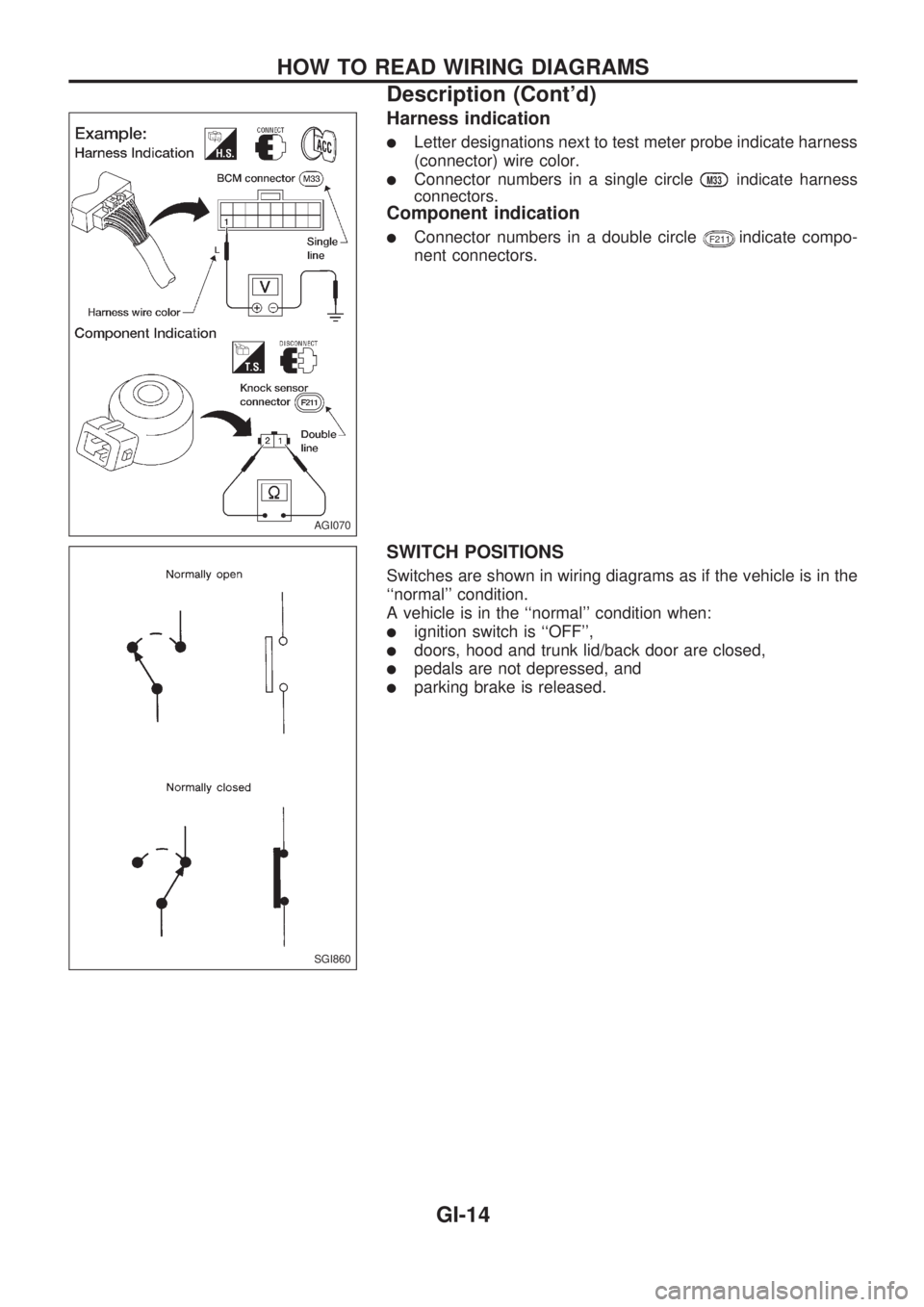
Harness indication
lLetter designations next to test meter probe indicate harness
(connector) wire color.
lConnector numbers in a single circleM33indicate harness
connectors.
Component indication
lConnector numbers in a double circleF211indicate compo-
nent connectors.
SWITCH POSITIONS
Switches are shown in wiring diagrams as if the vehicle is in the
``normal'' condition.
A vehicle is in the ``normal'' condition when:
lignition switch is ``OFF'',
ldoors, hood and trunk lid/back door are closed,
lpedals are not depressed, and
lparking brake is released.
AGI070
SGI860
HOW TO READ WIRING DIAGRAMS
Description (Cont'd)
GI-14
Page 837 of 1659

KEY TO SYMBOLS SIGNIFYING MEASUREMENTS OR PROCEDURES
Symbol Symbol explanation Symbol Symbol explanation
Check after disconnecting the connector
to be measured.Procedure with CONSULT
Check after connecting the connector to
be measured.Procedure without CONSULT
Insert key into ignition switch.A/C switch is ``OFF''.
Remove key from ignition switch.A/C switch is ``ON''.
Turn ignition switch to ``OFF'' position.Fan switch is ``ON''. (At any position
except for ``OFF'' position)
Turn ignition switch to ``ON'' position.Fan switch is ``OFF''.
Turn ignition switch to ``START'' position.Apply positive voltage from battery with
fuse directly to components.
Turn ignition switch from ``OFF'' to ``ACC''
position.Drive vehicle.
Turn ignition switch from ``ACC'' to ``OFF''
position.Disconnect battery negative cable.
Turn ignition switch from ``OFF'' to ``ON''
position.Depress brake pedal.
Turn ignition switch from ``ON'' to ``OFF''
position.Release brake pedal.
Do not start engine, or check with engine
stopped.Depress accelerator pedal.
Start engine, or check with engine run-
ning.Release accelerator pedal.
Apply parking brake.
Pin terminal check for SMJ type ECM
and TCM control unit connectors.
For details regarding the terminal
arrangement, refer to the foldout page.Release parking brake.
Check after engine is warmed up suffi-
ciently.
Voltage should be measured with a volt-
meter.
Circuit resistance should be measured
with an ohmmeter.
Current should be measured with an
ammeter.
HOW TO FOLLOW FLOW CHART IN TROUBLE DIAGNOSES
How to Follow This Flow Chart (Cont'd)
GI-33
Page 854 of 1659
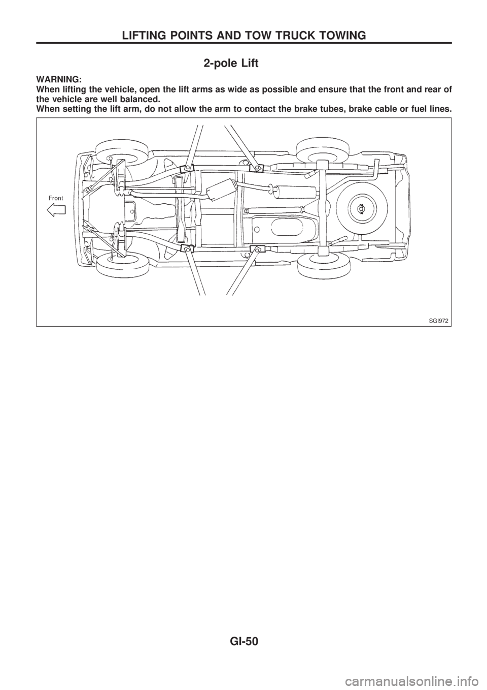
2-pole Lift
WARNING:
When lifting the vehicle, open the lift arms as wide as possible and ensure that the front and rear of
the vehicle are well balanced.
When setting the lift arm, do not allow the arm to contact the brake tubes, brake cable or fuel lines.
SGI972
LIFTING POINTS AND TOW TRUCK TOWING
GI-50
Page 855 of 1659
Tow Truck Towing
CAUTION:
lAll applicable local laws regarding the towing operation must be obeyed.
lIt is necessary to use proper towing equipment to avoid possible damage to the vehicle during
towing operation.
lAttach safety chains for all towing.
lWhen towing, make sure that the transmission, steering system and powertrain are in good order.
If any unit is damaged, a dolly must be used.
lWhen towing with the front wheels on the ground:
Turn the ignition key to the ``OFF'' position and secure the steering wheel in a straight ahead
position with a rope or similar device. Never place the ignition key in the ``LOCK'' position. This
will result in damage to the steering lock mechanism.
lWhen towing with the rear wheels on the ground, release the parking brake and move the gear-
shift lever to neutral position (``N'' position).
lNever tow vehicle from the rear (i.e., backward) with four wheels on the ground as this may cause
serious and expensive damage to the transmission.
lFor 4-wheel drive model:
Set the free-running hubs to the free position. Move the transfer case shift lever into the ``2H''
position and the transmission shift lever into the neutral (``N'') position.
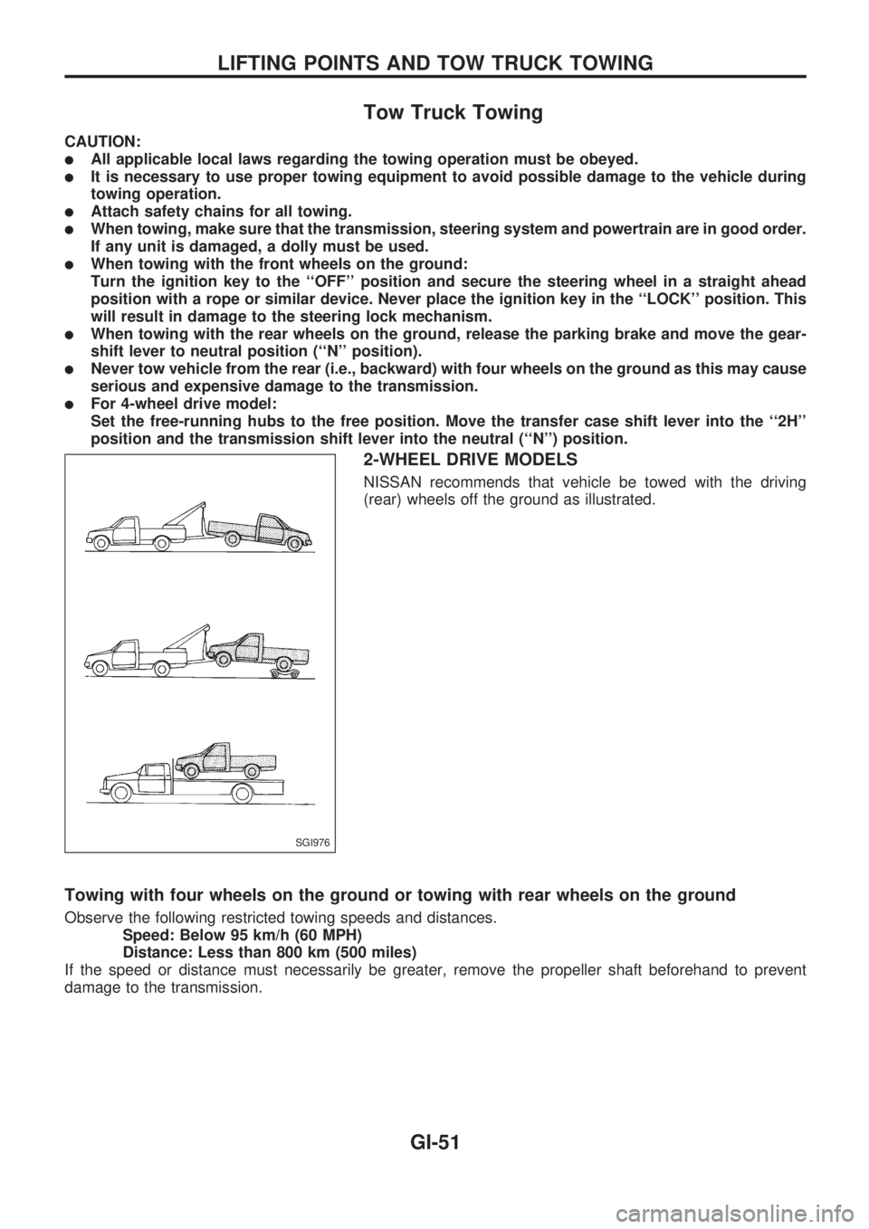
2-WHEEL DRIVE MODELS
NISSAN recommends that vehicle be towed with the driving
(rear) wheels off the ground as illustrated.
Towing with four wheels on the ground or towing with rear wheels on the ground
Observe the following restricted towing speeds and distances.
Speed: Below 95 km/h (60 MPH)
Distance: Less than 800 km (500 miles)
If the speed or distance must necessarily be greater, remove the propeller shaft beforehand to prevent
damage to the transmission.
SGI976
LIFTING POINTS AND TOW TRUCK TOWING
GI-51
Page 857 of 1659
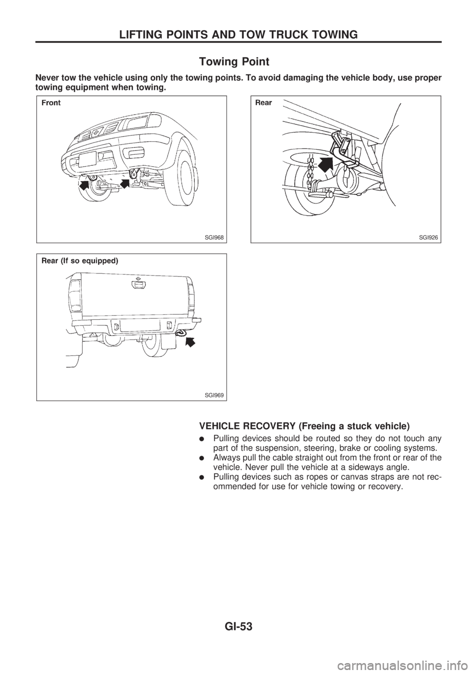
Towing Point
Never tow the vehicle using only the towing points. To avoid damaging the vehicle body, use proper
towing equipment when towing.
VEHICLE RECOVERY (Freeing a stuck vehicle)
lPulling devices should be routed so they do not touch any
part of the suspension, steering, brake or cooling systems.
lAlways pull the cable straight out from the front or rear of the
vehicle. Never pull the vehicle at a sideways angle.
lPulling devices such as ropes or canvas straps are not rec-
ommended for use for vehicle towing or recovery.
SGI968
SGI969
SGI926
LIFTING POINTS AND TOW TRUCK TOWING
GI-53
Page 864 of 1659
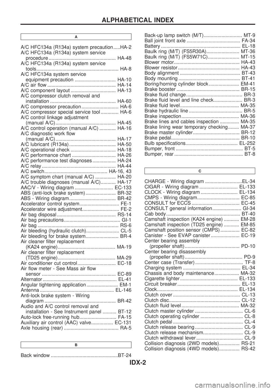
A
A/C HFC134a (R134a) system precaution .....HA-2
A/C HFC134a (R134a) system service
procedure ................................................. HA-48
A/C HFC134a (R134a) system service
tools............................................................ HA-8
A/C HFC134a system service
equipment precaution .............................. HA-10
A/C air flow .................................................. HA-14
A/C component layout ................................. HA-13
A/C compressor clutch removal and
installation ................................................ HA-60
A/C compressor precaution ........................... HA-6
A/C compressor special service tool ............. HA-6
A/C control linkage adjustment
(manual A/C) ............................................ HA-45
A/C control operation (manual A/C) ............ HA-16
A/C diagnostic work flow
(manual A/C) ............................................ HA-17
A/C lubricant (R134a) .................................. HA-50
A/C operational check ................................. HA-18
A/C performance chart ................................ HA-26
A/C performance test diagnoses ................. HA-24
A/C relay ...................................................... HA-44
A/C switch.............................................. HA-16, 43
A/C symptom chart (manual A/C) ............... HA-20
A/C trouble diagnoses (manual A/C)........... HA-17
AAC/V - Wiring diagram ............................ EC-133
ABS (anti-lock brake system) ...................... BR-32
ABS - Wiring diagram .................................. BR-42
Accelerator control system............................. FE-1
Accelerator wire adjustment........................... FE-2
Air bag disposal ........................................... RS-14
Air bag precautions ......................................... GI-1
Air bag ........................................................... RS-6
Air bleeding (hydraulic clutch)........................ CL-5
Air bleeding for brake system........................ BR-4
Air cleaner filter replacement
(KA24 engine).......................................... MA-19
Air cleaner filter replacement
(TD25 engine).......................................... MA-29
Air conditioner cut control ............................ EC-18
Air flow meter - See Mass air flow
sensor ...................................................... EC-89
Alternator ...................................................... EL-41
Angular tightening application ....................... EM-1
Antenna ...................................................... EL-146
Anti-lock brake system - Wiring
diagram .................................................... BR-42
Audio and A/C control removal and
installation - See Instrument panel .......... BT-12
Auto-lock free-running hub........................... FA-15
Auxiliary air control (AAC) valve................ EC-131
Axle housing (rear) ........................................ RA-5
B
Back window .................................................BT-24Back-up lamp switch (M/T)............................ MT-9
Ball joint front axle ....................................... FA-34
Battery .......................................................... EL-18
Baulk ring (M/T) (FS5R30A)........................ MT-36
Baulk ring (M/T) (FS5W71C)....................... MT-15
Blower motor................................................ HA-43
Blower resistor ............................................. HA-43
Body alignment ............................................ BT-43
Body mounting ............................................. BT-41
Boring/horning cylinder block ...................... EM-41
Brake booster .............................................. BR-15
Brake fluid change ......................................... BR-3
Brake fluid level and line check..................... BR-3
Brake fluid level ........................................... MA-35
Brake hydraulic line ....................................... BR-5
Brake inspection .......................................... MA-36
Brake lines and cables inspection .............. MA-35
Brake lining wear temporary checking ........ MA-37
Brake master cylinder .................................. BR-12
Brake pedal.................................................. BR-10
Bulb specifications...................................... EL-252
Bumper, front ................................................. BT-5
Bumper, rear .................................................. BT-8
C
CHARGE - Wiring diagram ...........................EL-34
CIGAR - Wiring diagram ............................ EL-133
CLOCK - Wiring diagram ........................... EL-134
CMPS - Wiring diagram............................... EC-85
CONSULT for ECCS ................................... EC-45
CONSULT general information ..................... GI-34
Cab body ...................................................... BT-40
Camshaft inspection (KA24 engine) ........... EM-28
Camshaft inspection (TD25 engine) ........... EM-85
Camshaft position sensor (CMPS) .............. EC-82
Canister - See EVAP canister ..................... EC-19
Center bearing assembly
(propeller shaft) ........................................ PD-10
Center bearing disassembly
(propeller shaft) .......................................... PD-9
Center case (Transfer) ................................... TF-8
Charging system .......................................... EL-34
Chassis and body maintenance .................. MA-32
Cigarette lighter .......................................... EL-133
Circuit breaker .............................................. EL-13
Clock........................................................... EL-134
Clutch cover ................................................. CL-13
Clutch disc.................................................... CL-12
Clutch fluid level .......................................... MA-32
Clutch master cylinder ................................... CL-6
Clutch operating cylinder ............................... CL-8
Clutch pedal ................................................... CL-4
Clutch release bearing ................................... CL-9
Clutch release mechanism............................. CL-9
Clutch withdrawal lever .................................. CL-9
Collision diagnosis (2WD models)............... RS-21
Collision diagnosis (4WD models)............... RS-42
ALPHABETICAL INDEX
IDX-2
Page 866 of 1659

EVAP vapor lines inspection ....................... MA-22
Electrical diagnoses ...................................... GI-21
Engine compartment .................................... BT-44
Engine control module (ECM) ....................... EC-5
Engine coolant temperature sensor
(ECTS) (KA24 engine) ............................. EC-95
Engine coolant temperature sensor
(ECTS) (TD25 engine) ........................... EC-209
Engine oil filter replacement
(KA24 engine).......................................... MA-20
Engine oil filter replacement
(TD25 engine).......................................... MA-24
Engine oil precautions .................................... GI-4
Engine oil replacement
(KA24 engine).......................................... MA-19
Engine oil replacement
(TD25 engine).......................................... MA-24
Engine outer component parts
(KA24 engine)............................................ EM-9
Engine outer component parts
(TD25 engine).......................................... EM-49
Engine removal (KA24 engine) ................... EM-36
Engine removal (TD25 engine) ................... EM-69
Engine room - See Engine
compartment............................................. BT-44
Engine speed sensor ................................. EC-219
Evaporative emission (EVAP) system ......... EC-19
Exhaust system inspection.......................... MA-32
Exhaust system .............................................. FE-5
Exterior ......................................................... BT-24
F
F/PUMP - Wiring diagram...........................EC-153
FCUT - Wiring diagram ............................. EC-225
FICD - Wiring diagram (KA24 engine) ...... EC-168
FICD - Wiring diagram (TD25 engine) ...... EC-230
Fan switch.................................................... HA-43
Fast idle cam (FIC) inspection and
adjustment................................................ EC-24
Final drive disassembly (C200) ................... PD-34
Final drive disassembly (H233B)................. PD-56
Final drive pre-inspection (C200) ................ PD-34
Final drive pre-inspection (H233B) .............. PD-56
Final drive removal and installation ............. PD-15
Floor trim ...................................................... BT-15
Flow charts.................................................... GI-31
Fluids ........................................................... MA-12
Flywheel (clutch) .......................................... CL-12
Flywheel runout (KA24 engine)................... EM-45
Flywheel runout (TD25 engine)................... EM-80
Fog lamp, rear .............................................. EL-72
Fork rod (M/T) (FS5R30A) .......................... MT-38
Fork rod (M/T) (FS5W71C) ......................... MT-17
Front axle ..................................................... FA-12
Front bumper.................................................. BT-5
Front case (Transfer) ..................................... TF-8
Front combination lamp removal and
installation................................................... BT-5Front disc brake ........................................... BR-21
Front door..................................................... BT-10
Front drive shaft (Transfer) ............................ TF-9
Front final drive disassembly (4WD) ........... PD-17
Front final drive pre-inspection (4WD) ........ PD-17
Front final drive removal and installa-
tion (4WD) ................................................ PD-14
Front seat belt................................................ RS-3
Front seat ..................................................... BT-30
Front suspension.......................................... FA-26
Front washer .............................................. EL-120
Front wiper ................................................. EL-120
Fuel check valve .......................................... EC-20
Fuel cut control (at no load & high
engine speed) (KA24 engine) .................. EC-18
Fuel cut control (at no load & high
engine speed) ........................................ EC-225
Fuel filter replacement (KA24 engine) ........ MA-18
Fuel filter replacement (TD25 engine) ........ MA-27
Fuel injector ............................................... EC-144
Fuel line inspection (KA24 engine) ............. MA-18
Fuel line inspection (TD25 engine) ............. MA-28
Fuel precautions ............................................. GI-5
Fuel pressure check .................................... EC-22
Fuel pressure release .................................. EC-22
Fuel pump .................................................. EC-151
Fuel pump relay ......................................... EC-156
Fuel system .................................................... FE-3
Fuel tank vacuum relief valve...................... EC-20
Fuse block.................................................. Foldout
Fuse.............................................................. EL-13
Fusible link ................................................... EL-13G
GLOW - Wiring diagram .............................EC-197
Garage jack and safety stand....................... GI-49
Gear components (M/T) (FS5R30A) ........... MT-36
Gear components (M/T) (FS5W71C) .......... MT-15
Glass ............................................................ BT-10
Glow plug ................................................... EC-208
Glow relay .................................................. EC-208
Grease ......................................................... MA-12
Ground clearance ......................................... GI-44
Ground distribution ....................................... EL-14
H
H/AIM - Wiring diagram .................................EL-64
H/LAMP - Wiring diagram ............................ EL-44
H02S - Wiring diagram .............................. EC-124
HFC134a (R134a) system precaution ........... HA-2
HFC134a (R134a) system service
procedure ................................................. HA-48
HFC134a (R134a) system service
tools............................................................ HA-8
HFC134a system service equipment
precaution ................................................ HA-10
ALPHABETICAL INDEX
IDX-4