1998 NISSAN PICK-UP brake
[x] Cancel search: brakePage 41 of 1659

G SENSOR
Always replace G sensor if bumped or dropped. Otherwise,
performance characteristics of G sensor will be changed,
which in turn changes ABS control performance character-
istics.
ABS ACTUATOR AND ELECTRIC UNIT
Removal
1. Disconnect battery cable.
2. Drain brake fluid. Refer to ``Changing Brake Fluid'', BR-3.
3. Remove mounting bracket fixing bolts and nuts.
4. Disconnect connector, brake pipes and remove fixing nuts.
Installation
CAUTION:
After installation, refill brake fluid. Then bleed air. Refer to
``Bleeding Brake System'', BR-4.
1. Connect brake pipes temporarily.
2. Tighten fixing bolts and nuts.
3. Tighten brake pipes.
4. Connect connector and battery cable.
SBR074E
SBR075E
ANTI-LOCK BRAKE SYSTEM
Removal and Installation (Cont'd)
BR-37
Page 42 of 1659
How to Perform Trouble Diagnoses for Quick
and Accurate Repair
INTRODUCTION
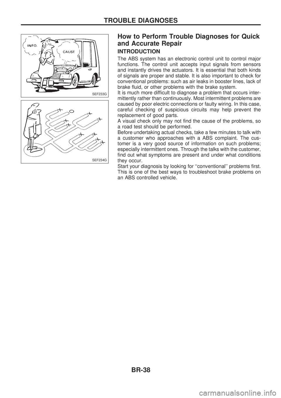
The ABS system has an electronic control unit to control major
functions. The control unit accepts input signals from sensors
and instantly drives the actuators. It is essential that both kinds
of signals are proper and stable. It is also important to check for
conventional problems: such as air leaks in booster lines, lack of
brake fluid, or other problems with the brake system.
It is much more difficult to diagnose a problem that occurs inter-
mittently rather than continuously. Most intermittent problems are
caused by poor electric connections or faulty wiring. In this case,
careful checking of suspicious circuits may help prevent the
replacement of good parts.
A visual check only may not find the cause of the problems, so
a road test should be performed.
Before undertaking actual checks, take a few minutes to talk with
a customer who approaches with a ABS complaint. The cus-
tomer is a very good source of information on such problems;
especially intermittent ones. Through the talks with the customer,
find out what symptoms are present and under what conditions
they occur.
Start your diagnosis by looking for ``conventional'' problems first.
This is one of the best ways to troubleshoot brake problems on
an ABS controlled vehicle.
SEF233G
SEF234G
TROUBLE DIAGNOSES
BR-38
Page 43 of 1659
Preliminary Check
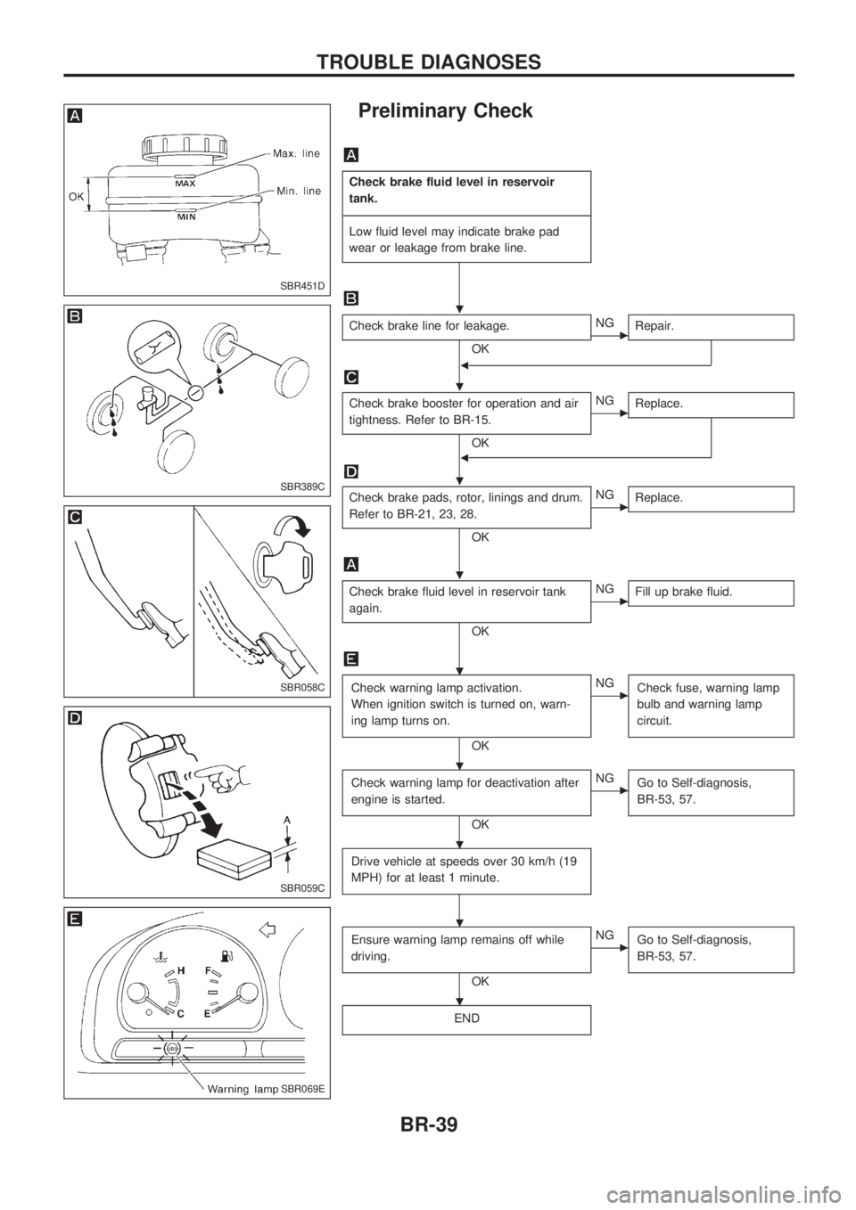
Check brake fluid level in reservoir
tank.
-------------------------------------------------------------------------------------------------------------------------------------------------------------------------------------------------------------------------------------------------------------------------------------------------------------
Low fluid level may indicate brake pad
wear or leakage from brake line.
Check brake line for leakage.
OKcNG
Repair.
b
Check brake booster for operation and air
tightness. Refer to BR-15.
OK
cNG
Replace.
b
Check brake pads, rotor, linings and drum.
Refer to BR-21, 23, 28.
OK
cNG
Replace.
Check brake fluid level in reservoir tank
again.
OK
cNG
Fill up brake fluid.
Check warning lamp activation.
When ignition switch is turned on, warn-
ing lamp turns on.
OK
cNG
Check fuse, warning lamp
bulb and warning lamp
circuit.
Check warning lamp for deactivation after
engine is started.
OK
cNG
Go to Self-diagnosis,
BR-53, 57.
Drive vehicle at speeds over 30 km/h (19
MPH) for at least 1 minute.
Ensure warning lamp remains off while
driving.
OK
cNG
Go to Self-diagnosis,
BR-53, 57.
END
SBR451D
SBR389C
SBR058C
SBR059C
SBR069E
.
.
.
.
.
.
.
.
.
TROUBLE DIAGNOSES
BR-39
Page 57 of 1659
Self-diagnosis
FUNCTION
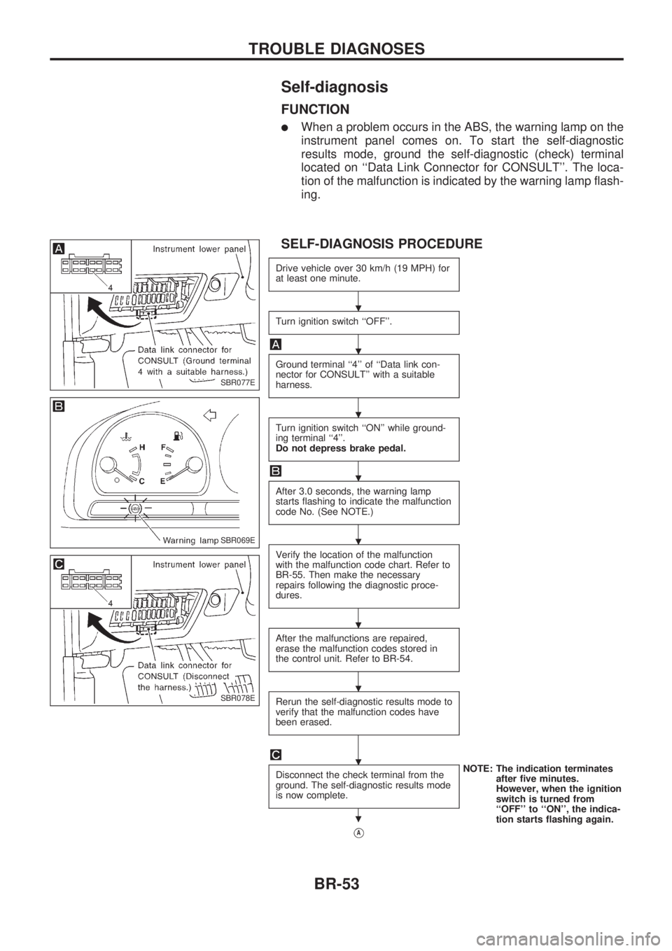
lWhen a problem occurs in the ABS, the warning lamp on the
instrument panel comes on. To start the self-diagnostic
results mode, ground the self-diagnostic (check) terminal
located on ``Data Link Connector for CONSULT''. The loca-
tion of the malfunction is indicated by the warning lamp flash-
ing.
SELF-DIAGNOSIS PROCEDURE
Drive vehicle over 30 km/h (19 MPH) for
at least one minute.
Turn ignition switch ``OFF''.
Ground terminal ``4'' of ``Data link con-
nector for CONSULT'' with a suitable
harness.
Turn ignition switch ``ON'' while ground-
ing terminal ``4''.
Do not depress brake pedal.
After 3.0 seconds, the warning lamp
starts flashing to indicate the malfunction
code No. (See NOTE.)
Verify the location of the malfunction
with the malfunction code chart. Refer to
BR-55. Then make the necessary
repairs following the diagnostic proce-
dures.
After the malfunctions are repaired,
erase the malfunction codes stored in
the control unit. Refer to BR-54.
Rerun the self-diagnostic results mode to
verify that the malfunction codes have
been erased.
Disconnect the check terminal from the
ground. The self-diagnostic results mode
is now complete.NOTE: The indication terminates
after five minutes.
However, when the ignition
switch is turned from
``OFF'' to ``ON'', the indica-
tion starts flashing again.
VA
SBR077E
SBR069E
SBR078E
.
.
.
.
.
.
.
.
.
TROUBLE DIAGNOSES
BR-53
Page 65 of 1659
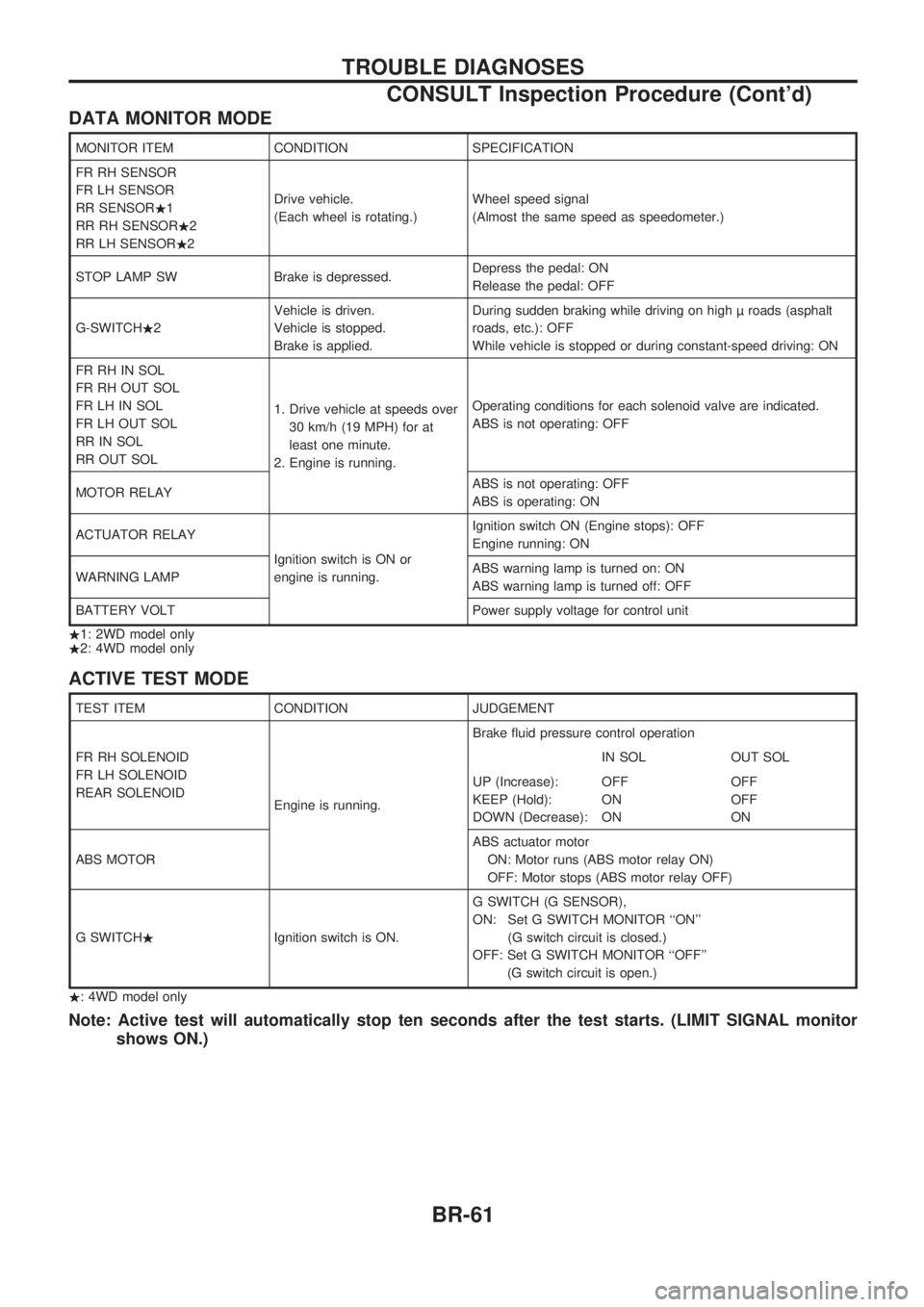
DATA MONITOR MODE
MONITOR ITEM CONDITION SPECIFICATION
FR RH SENSOR
FR LH SENSOR
RR SENSOR.1
RR RH SENSOR.2
RR LH SENSOR.2Drive vehicle.
(Each wheel is rotating.)Wheel speed signal
(Almost the same speed as speedometer.)
STOP LAMP SW Brake is depressed.Depress the pedal: ON
Release the pedal: OFF
G-SWITCH.2Vehicle is driven.
Vehicle is stopped.
Brake is applied.During sudden braking while driving on high roads (asphalt
roads, etc.): OFF
While vehicle is stopped or during constant-speed driving: ON
FR RH IN SOL
FR RH OUT SOL
FR LH IN SOL
FR LH OUT SOL
RR IN SOL
RR OUT SOL1. Drive vehicle at speeds over
30 km/h (19 MPH) for at
least one minute.
2. Engine is running.Operating conditions for each solenoid valve are indicated.
ABS is not operating: OFF
MOTOR RELAYABS is not operating: OFF
ABS is operating: ON
ACTUATOR RELAY
Ignition switch is ON or
engine is running.Ignition switch ON (Engine stops): OFF
Engine running: ON
WARNING LAMPABS warning lamp is turned on: ON
ABS warning lamp is turned off: OFF
BATTERY VOLT Power supply voltage for control unit
.1: 2WD model only
.2: 4WD model only
ACTIVE TEST MODE
TEST ITEM CONDITION JUDGEMENT
FR RH SOLENOID
FR LH SOLENOID
REAR SOLENOID
Engine is running.Brake fluid pressure control operation
IN SOL OUT SOL
UP (Increase):
KEEP (Hold):
DOWN (Decrease):OFF
ON
ONOFF
OFF
ON
ABS MOTORABS actuator motor
ON: Motor runs (ABS motor relay ON)
OFF: Motor stops (ABS motor relay OFF)
G SWITCH.Ignition switch is ON.G SWITCH (G SENSOR),
ON: Set G SWITCH MONITOR ``ON''
(G switch circuit is closed.)
OFF: Set G SWITCH MONITOR ``OFF''
(G switch circuit is open.)
.: 4WD model only
Note: Active test will automatically stop ten seconds after the test starts. (LIMIT SIGNAL monitor
shows ON.)
TROUBLE DIAGNOSES
CONSULT Inspection Procedure (Cont'd)
BR-61
Page 76 of 1659
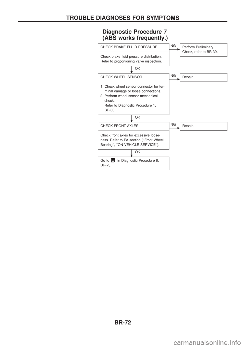
Diagnostic Procedure 7
(ABS works frequently.)
CHECK BRAKE FLUID PRESSURE.
-------------------------------------------------------------------------------------------------------------------------------------------------------------------------------------------------------------------------------------------------------------------------------------------------------------
Check brake fluid pressure distribution.
Refer to proportioning valve inspection.
OK
cNG
Perform Preliminary
Check, refer to BR-39.
CHECK WHEEL SENSOR.
-------------------------------------------------------------------------------------------------------------------------------------------------------------------------------------------------------------------------------------------------------------------------------------------------------------
1. Check wheel sensor connector for ter-
minal damage or loose connections.
2. Perform wheel sensor mechanical
check.
Refer to Diagnostic Procedure 1,
BR-63.
OK
cNG
Repair.
CHECK FRONT AXLES.
-------------------------------------------------------------------------------------------------------------------------------------------------------------------------------------------------------------------------------------------------------------------------------------------------------------
Check front axles for excessive loose-
ness. Refer to FA section (``Front Wheel
Bearing'', ``ON-VEHICLE SERVICE'').
OK
cNG
Repair.
Go toin Diagnostic Procedure 8,
BR-73.
.
.
.
TROUBLE DIAGNOSES FOR SYMPTOMS
BR-72
Page 77 of 1659
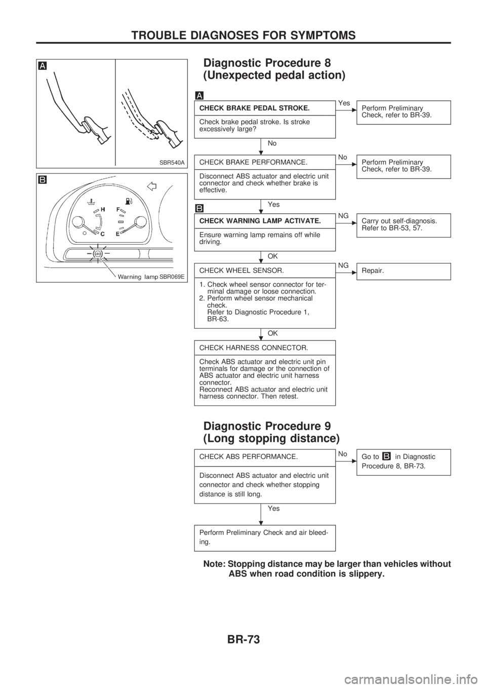
Diagnostic Procedure 8
(Unexpected pedal action)
CHECK BRAKE PEDAL STROKE.
-------------------------------------------------------------------------------------------------------------------------------------------------------------------------------------------------------------------------------------------------------------------------------------------------------------
Check brake pedal stroke. Is stroke
excessively large?
No
cYes
Perform Preliminary
Check, refer to BR-39.
CHECK BRAKE PERFORMANCE.
-------------------------------------------------------------------------------------------------------------------------------------------------------------------------------------------------------------------------------------------------------------------------------------------------------------
Disconnect ABS actuator and electric unit
connector and check whether brake is
effective.
Yes
cNo
Perform Preliminary
Check, refer to BR-39.
CHECK WARNING LAMP ACTIVATE.
-------------------------------------------------------------------------------------------------------------------------------------------------------------------------------------------------------------------------------------------------------------------------------------------------------------
Ensure warning lamp remains off while
driving.
OK
cNG
Carry out self-diagnosis.
Refer to BR-53, 57.
CHECK WHEEL SENSOR.
-------------------------------------------------------------------------------------------------------------------------------------------------------------------------------------------------------------------------------------------------------------------------------------------------------------
1. Check wheel sensor connector for ter-
minal damage or loose connection.
2. Perform wheel sensor mechanical
check.
Refer to Diagnostic Procedure 1,
BR-63.
OK
cNG
Repair.
CHECK HARNESS CONNECTOR.
-------------------------------------------------------------------------------------------------------------------------------------------------------------------------------------------------------------------------------------------------------------------------------------------------------------
Check ABS actuator and electric unit pin
terminals for damage or the connection of
ABS actuator and electric unit harness
connector.
Reconnect ABS actuator and electric unit
harness connector. Then retest.
Diagnostic Procedure 9
(Long stopping distance)
CHECK ABS PERFORMANCE.
-------------------------------------------------------------------------------------------------------------------------------------------------------------------------------------------------------------------------------------------------------------------------------------------------------------
Disconnect ABS actuator and electric unit
connector and check whether stopping
distance is still long.
Yes
cNo
Go toin Diagnostic
Procedure 8, BR-73.
Perform Preliminary Check and air bleed-
ing.
Note: Stopping distance may be larger than vehicles without
ABS when road condition is slippery.
SBR540A
SBR069E
.
.
.
.
.
TROUBLE DIAGNOSES FOR SYMPTOMS
BR-73
Page 78 of 1659
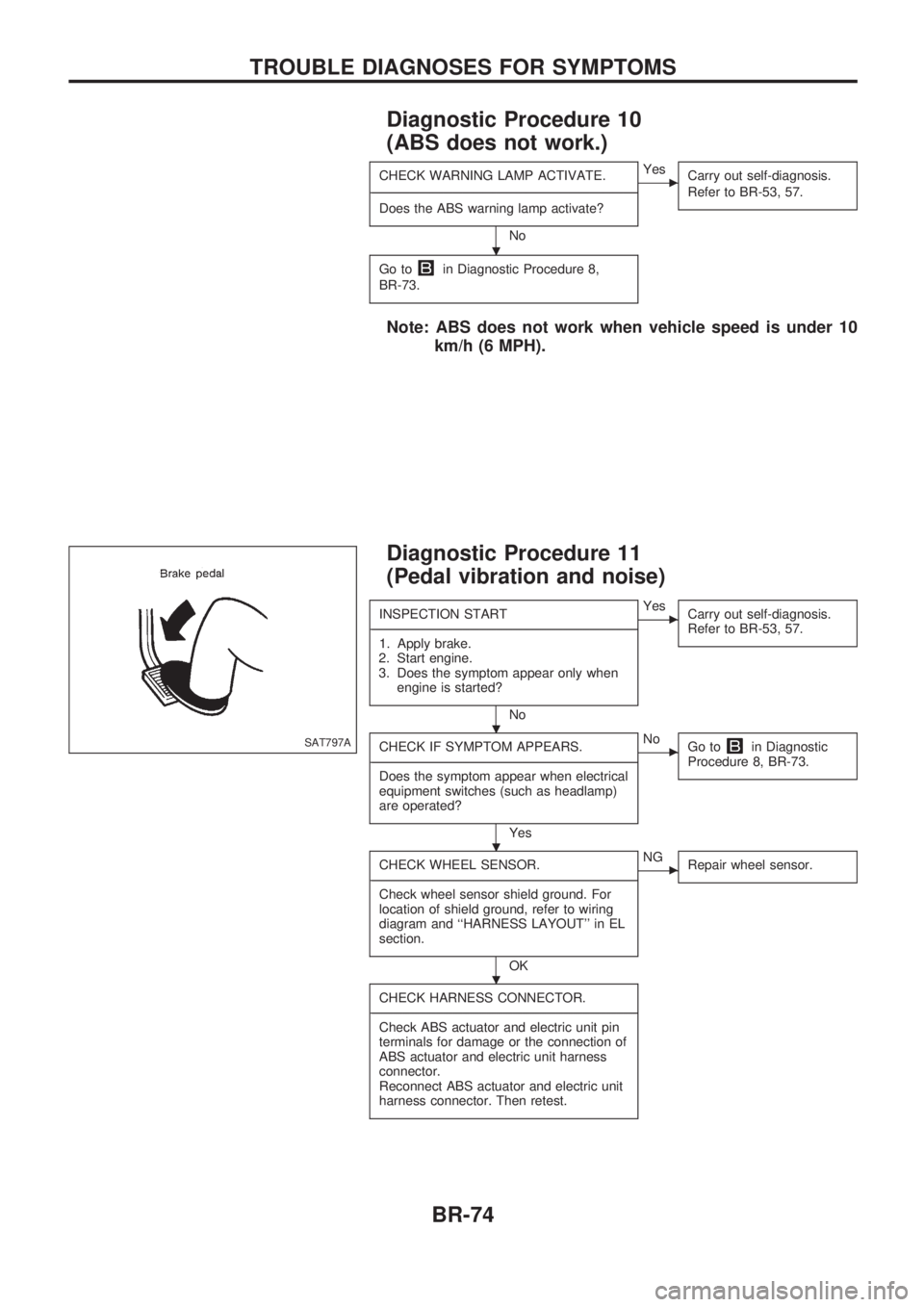
Diagnostic Procedure 10
(ABS does not work.)
CHECK WARNING LAMP ACTIVATE.
-------------------------------------------------------------------------------------------------------------------------------------------------------------------------------------------------------------------------------------------------------------------------------------------------------------
Does the ABS warning lamp activate?
No
cYes
Carry out self-diagnosis.
Refer to BR-53, 57.
Go toin Diagnostic Procedure 8,
BR-73.
Note: ABS does not work when vehicle speed is under 10
km/h (6 MPH).
Diagnostic Procedure 11
(Pedal vibration and noise)
INSPECTION START
-------------------------------------------------------------------------------------------------------------------------------------------------------------------------------------------------------------------------------------------------------------------------------------------------------------
1. Apply brake.
2. Start engine.
3. Does the symptom appear only when
engine is started?
No
cYes
Carry out self-diagnosis.
Refer to BR-53, 57.
CHECK IF SYMPTOM APPEARS.
-------------------------------------------------------------------------------------------------------------------------------------------------------------------------------------------------------------------------------------------------------------------------------------------------------------
Does the symptom appear when electrical
equipment switches (such as headlamp)
are operated?
Yes
cNo
Go toin Diagnostic
Procedure 8, BR-73.
CHECK WHEEL SENSOR.
-------------------------------------------------------------------------------------------------------------------------------------------------------------------------------------------------------------------------------------------------------------------------------------------------------------
Check wheel sensor shield ground. For
location of shield ground, refer to wiring
diagram and ``HARNESS LAYOUT'' in EL
section.
OK
cNG
Repair wheel sensor.
CHECK HARNESS CONNECTOR.
-------------------------------------------------------------------------------------------------------------------------------------------------------------------------------------------------------------------------------------------------------------------------------------------------------------
Check ABS actuator and electric unit pin
terminals for damage or the connection of
ABS actuator and electric unit harness
connector.
Reconnect ABS actuator and electric unit
harness connector. Then retest.
SAT797A
.
.
.
.
TROUBLE DIAGNOSES FOR SYMPTOMS
BR-74