1998 NISSAN PICK-UP brake
[x] Cancel search: brakePage 79 of 1659
Note: ABS may operate and cause vibration under any of the
following conditions.
lApplying brake gradually when shifting or operating
clutch.
lLow friction (slippery) road.
lHigh speed cornering.
lDriving over bumps and pot holes.
lEngine speed is over 5,000 rpm with vehicle stopped.
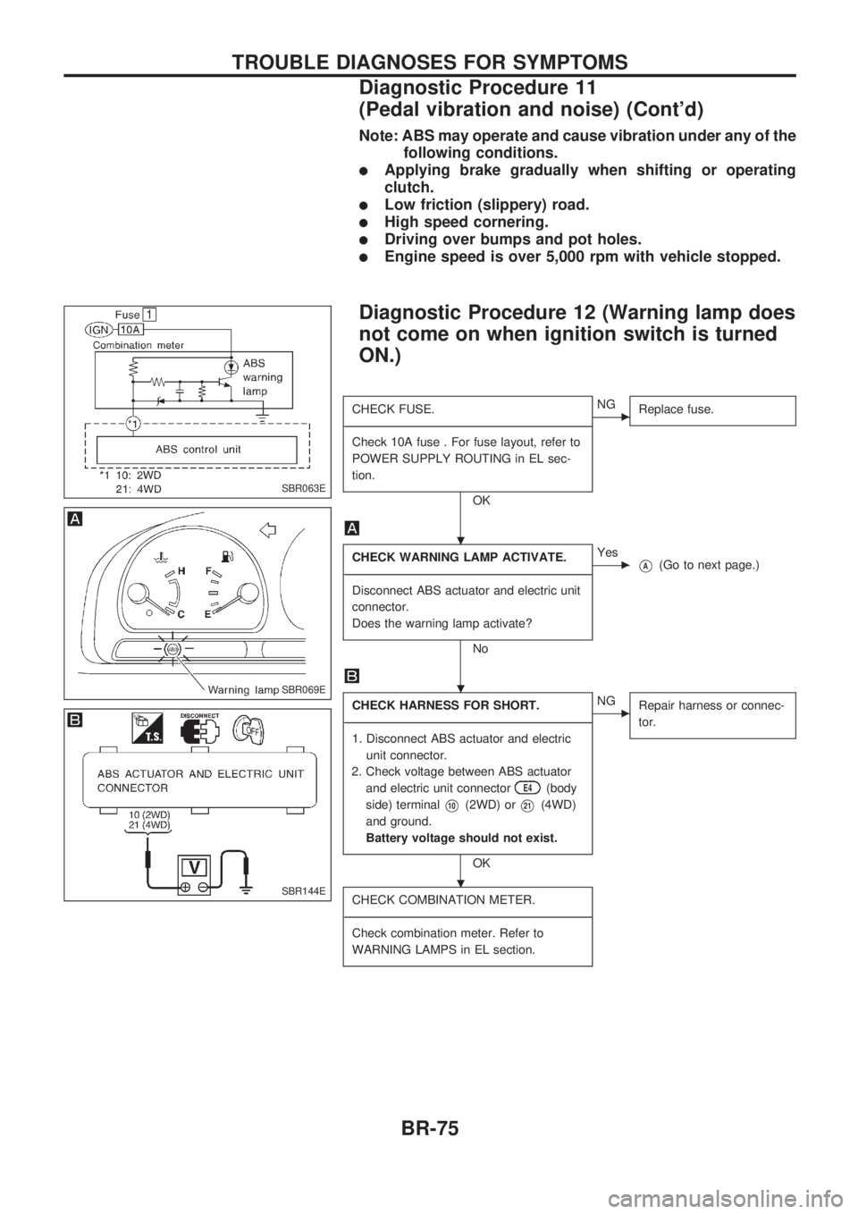
Diagnostic Procedure 12 (Warning lamp does
not come on when ignition switch is turned
ON.)
CHECK FUSE.
-------------------------------------------------------------------------------------------------------------------------------------------------------------------------------------------------------------------------------------------------------------------------------------------------------------
Check 10A fuse . For fuse layout, refer to
POWER SUPPLY ROUTING in EL sec-
tion.
OK
cNG
Replace fuse.
CHECK WARNING LAMP ACTIVATE.
-------------------------------------------------------------------------------------------------------------------------------------------------------------------------------------------------------------------------------------------------------------------------------------------------------------
Disconnect ABS actuator and electric unit
connector.
Does the warning lamp activate?
No
cYes
VA(Go to next page.)
CHECK HARNESS FOR SHORT.
-------------------------------------------------------------------------------------------------------------------------------------------------------------------------------------------------------------------------------------------------------------------------------------------------------------
1. Disconnect ABS actuator and electric
unit connector.
2. Check voltage between ABS actuator
and electric unit connector
E4(body
side) terminal
V10(2WD) orV21(4WD)
and ground.
Battery voltage should not exist.
OK
cNG
Repair harness or connec-
tor.
CHECK COMBINATION METER.
-------------------------------------------------------------------------------------------------------------------------------------------------------------------------------------------------------------------------------------------------------------------------------------------------------------
Check combination meter. Refer to
WARNING LAMPS in EL section.
SBR063E
SBR069E
SBR144E
.
.
.
TROUBLE DIAGNOSES FOR SYMPTOMS
Diagnostic Procedure 11
(Pedal vibration and noise) (Cont'd)
BR-75
Page 82 of 1659
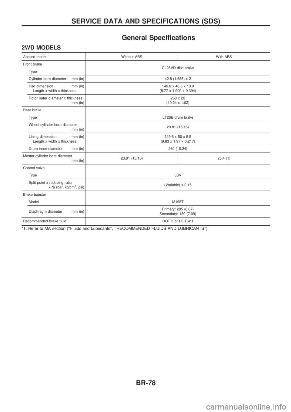
General Specifications
2WD MODELS
Applied model Without ABS With ABS
Front brake
CL28VD disc brake
Type
Cylinder bore diameter mm (in) 42.8 (1.685) x 2
Pad dimension mm (in)
Length x width x thickness146.6 x 48.5 x 10.0
(5.77 x 1.909 x 0.394)
Rotor outer diameter x thickness
mm (in)260x26
(10.24 x 1.02)
Rear brake
TypeLT26B drum brake
Wheel cylinder bore diameter
mm (in)23.81 (15/16)
Lining dimension mm (in)
Length x width x thickness249.6 x 50 x 5.5
(9.83 x 1.97 x 0.217)
Drum inner diameter mm (in) 260 (10.24)
Master cylinder bore diameter
mm (in)23.81 (15/16) 25.4 (1)
Control valve
TypeLSV
Split point x reducing ratio
kPa (bar, kg/cm
2, psi)(Variable) x 0.15
Brake booster
ModelM195T
Diaphragm diameter mm (in)Primary: 205 (8.07)
Secondary: 180 (7.09)
Recommended brake fluid DOT 3 or DOT 4*1
*1: Refer to MA section (``Fluids and Lubricants'', ``RECOMMENDED FLUIDS AND LUBRICANTS'').
SERVICE DATA AND SPECIFICATIONS (SDS)
BR-78
Page 83 of 1659
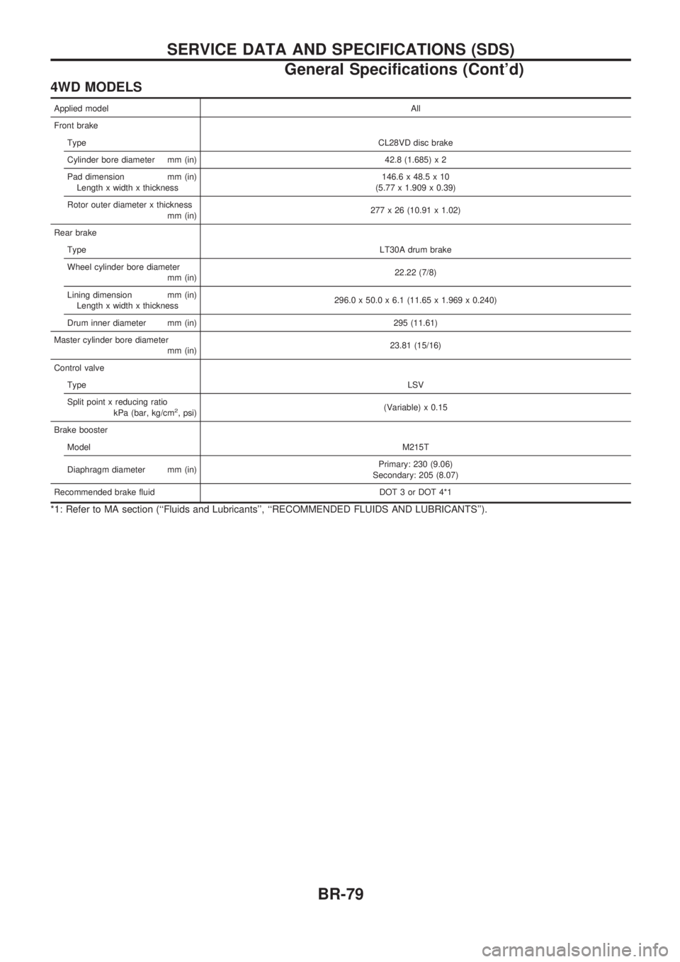
4WD MODELS
Applied modelAll
Front brake
TypeCL28VD disc brake
Cylinder bore diameter mm (in) 42.8 (1.685) x 2
Pad dimension mm (in)
Length x width x thickness146.6 x 48.5 x 10
(5.77 x 1.909 x 0.39)
Rotor outer diameter x thickness
mm (in)277 x 26 (10.91 x 1.02)
Rear brake
TypeLT30A drum brake
Wheel cylinder bore diameter
mm (in)22.22 (7/8)
Lining dimension mm (in)
Length x width x thickness296.0 x 50.0 x 6.1 (11.65 x 1.969 x 0.240)
Drum inner diameter mm (in) 295 (11.61)
Master cylinder bore diameter
mm (in)23.81 (15/16)
Control valve
TypeLSV
Split point x reducing ratio
kPa (bar, kg/cm
2, psi)(Variable) x 0.15
Brake booster
ModelM215T
Diaphragm diameter mm (in)Primary: 230 (9.06)
Secondary: 205 (8.07)
Recommended brake fluid DOT 3 or DOT 4*1
*1: Refer to MA section (``Fluids and Lubricants'', ``RECOMMENDED FLUIDS AND LUBRICANTS'').
SERVICE DATA AND SPECIFICATIONS (SDS)
General Specifications (Cont'd)
BR-79
Page 84 of 1659

Inspection and Adjustment
DISC BRAKEUnit: mm (in)
Brake model CL28VD
Pad wear limit
Minimum thickness 2.0 (0.079)
Rotor repair limit
Minimum thickness 24.0 (0.945)
DRUM BRAKEUnit: mm (in)
Brake model LT26B LT30A
Lining wear limit
Minimum thickness 1.5 (0.059)
Drum repair limit
Maximum inner
diameter261.5 (10.30) 296.5 (11.67)
Out-of-round limit 0.15 (0.0059)
BRAKE PEDALUnit: mm (in)
Free height ``H''*
LHD 209 - 219 (8.23 - 8.62)
RHD 203 - 213 (7.99 - 8.39)
Depressed height ``D''
[under force of 490 N (50
kg, 110 lb) with engine run-
ning]120.0 (4.72)
Clearance ``C'' between
pedal stopper and threaded
end of stop lamp switch0.3 - 1.0 (0.012 - 0.039)
Pedal free play
At clevis 1.0 - 3.0 (0.039 - 0.118)
At pedal pad 4 - 12 (0.16 - 0.47)
*: Measured from surface of melt sheet to pedal pad.
PARKING BRAKE CONTROL
Control type Stick lever Center lever
Lever stroke
[under force of 196 N
(20 kg, 44 lb)]2WD 8 - 10 Ð
4WD 10-12 8-10
Lever stroke when warning
switch comes on1
SERVICE DATA AND SPECIFICATIONS (SDS)
BR-80
Page 86 of 1659
Precautions
lRecommended fluid is brake fluid ``DOT 3'' or ``DOT 4''.
Refer to MA section (``Fluids and Lubricants'', ``RECOM-
MENDED FLUIDS AND LUBRICANTS'').
lDo not reuse drained brake fluid.
lBe careful not to splash brake fluid on painted areas.
lWhen removing and installing clutch piping, use Tool.
lUse new brake fluid to clean or wash all parts of master
cylinder, operating cylinder and clutch damper.
lNever use mineral oils such as gasoline or kerosene. It
will ruin the rubber parts of the hydraulic system.
WARNING:
After cleaning clutch disc, wipe it with a dust collector. Do
not use compressed air.
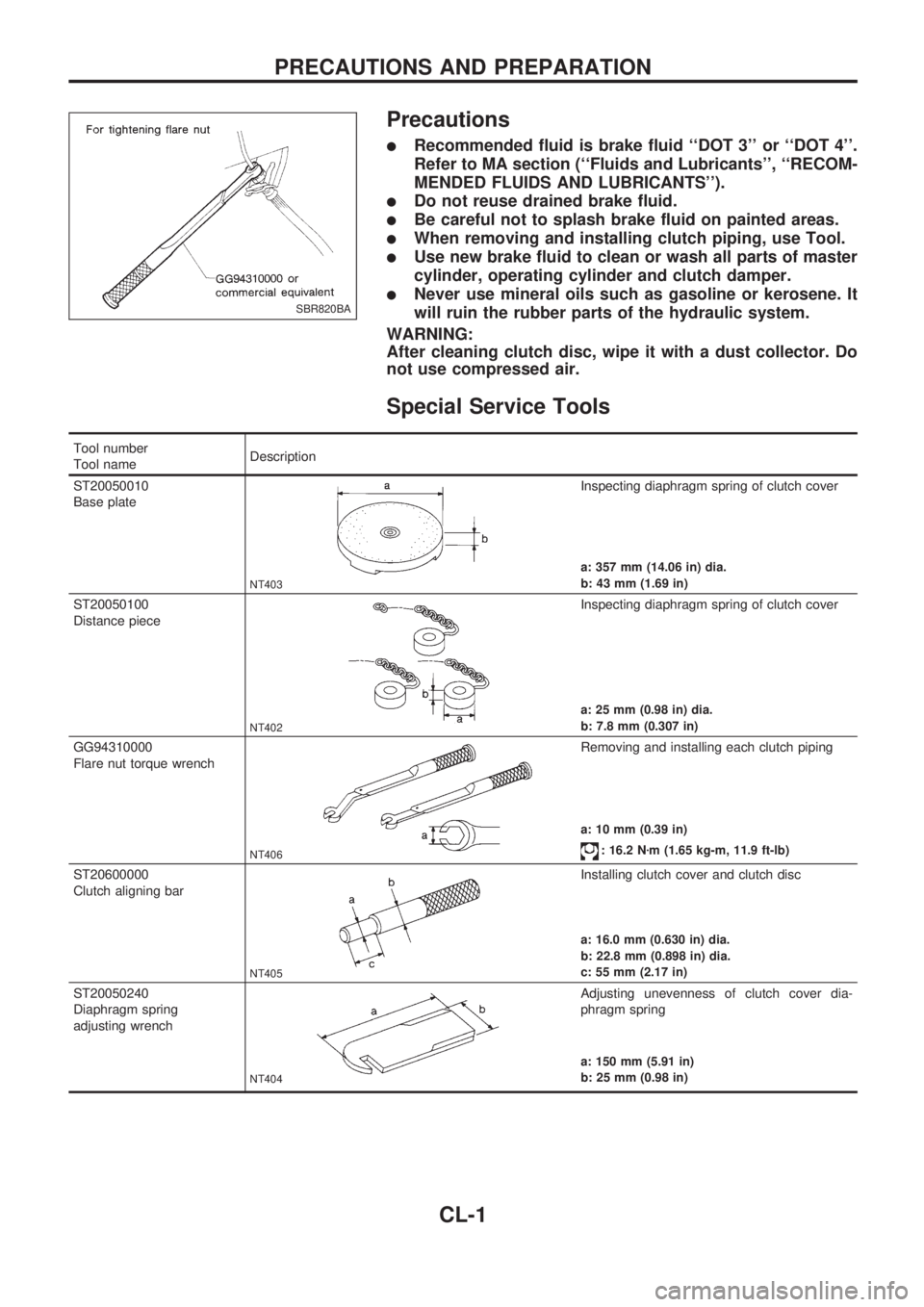
Special Service Tools
Tool number
Tool nameDescription
ST20050010
Base plate
NT403
Inspecting diaphragm spring of clutch cover
a: 357 mm (14.06 in) dia.
b: 43 mm (1.69 in)
ST20050100
Distance piece
NT402
Inspecting diaphragm spring of clutch cover
a: 25 mm (0.98 in) dia.
b: 7.8 mm (0.307 in)
GG94310000
Flare nut torque wrench
NT406
Removing and installing each clutch piping
a: 10 mm (0.39 in)
: 16.2 Nzm (1.65 kg-m, 11.9 ft-lb)
ST20600000
Clutch aligning bar
NT405
Installing clutch cover and clutch disc
a: 16.0 mm (0.630 in) dia.
b: 22.8 mm (0.898 in) dia.
c: 55 mm (2.17 in)
ST20050240
Diaphragm spring
adjusting wrench
NT404
Adjusting unevenness of clutch cover dia-
phragm spring
a: 150 mm (5.91 in)
b: 25 mm (0.98 in)
SBR820BA
PRECAUTIONS AND PREPARATION
CL-1
Page 90 of 1659
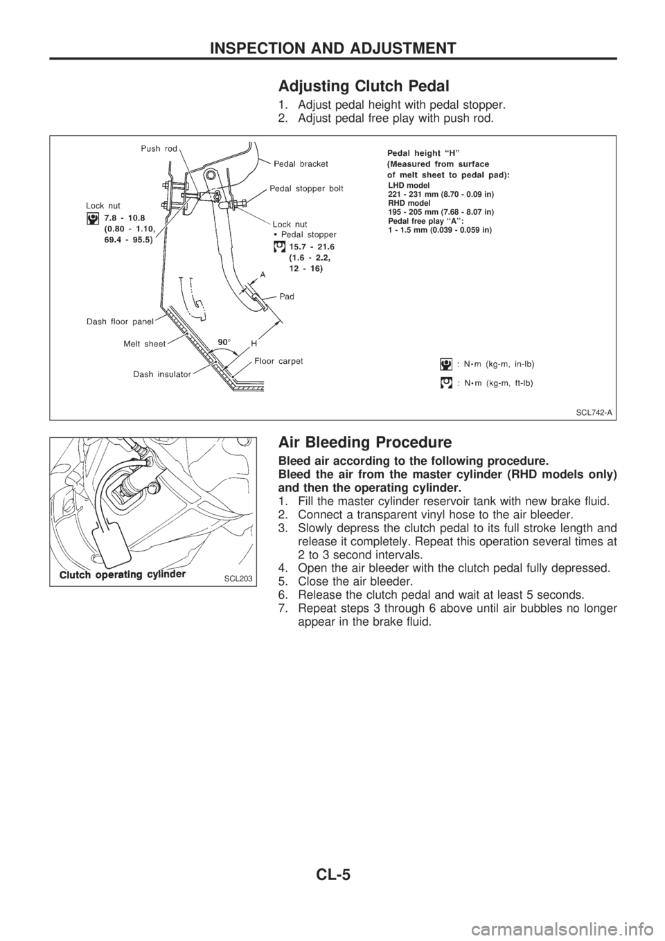
Adjusting Clutch Pedal
1. Adjust pedal height with pedal stopper.
2. Adjust pedal free play with push rod.
Air Bleeding Procedure
Bleed air according to the following procedure.
Bleed the air from the master cylinder (RHD models only)
and then the operating cylinder.
1. Fill the master cylinder reservoir tank with new brake fluid.
2. Connect a transparent vinyl hose to the air bleeder.
3. Slowly depress the clutch pedal to its full stroke length and
release it completely. Repeat this operation several times at
2 to 3 second intervals.
4. Open the air bleeder with the clutch pedal fully depressed.
5. Close the air bleeder.
6. Release the clutch pedal and wait at least 5 seconds.
7. Repeat steps 3 through 6 above until air bubbles no longer
appear in the brake fluid.
SCL742-A
.LHD model
221 - 231 mm (8.70 - 0.09 in)
RHD model
195 - 205 mm (7.68 - 8.07 in)
Pedal free play ``A'':
1 - 1.5 mm (0.039 - 0.059 in)
SCL203
INSPECTION AND ADJUSTMENT
CL-5
Page 140 of 1659
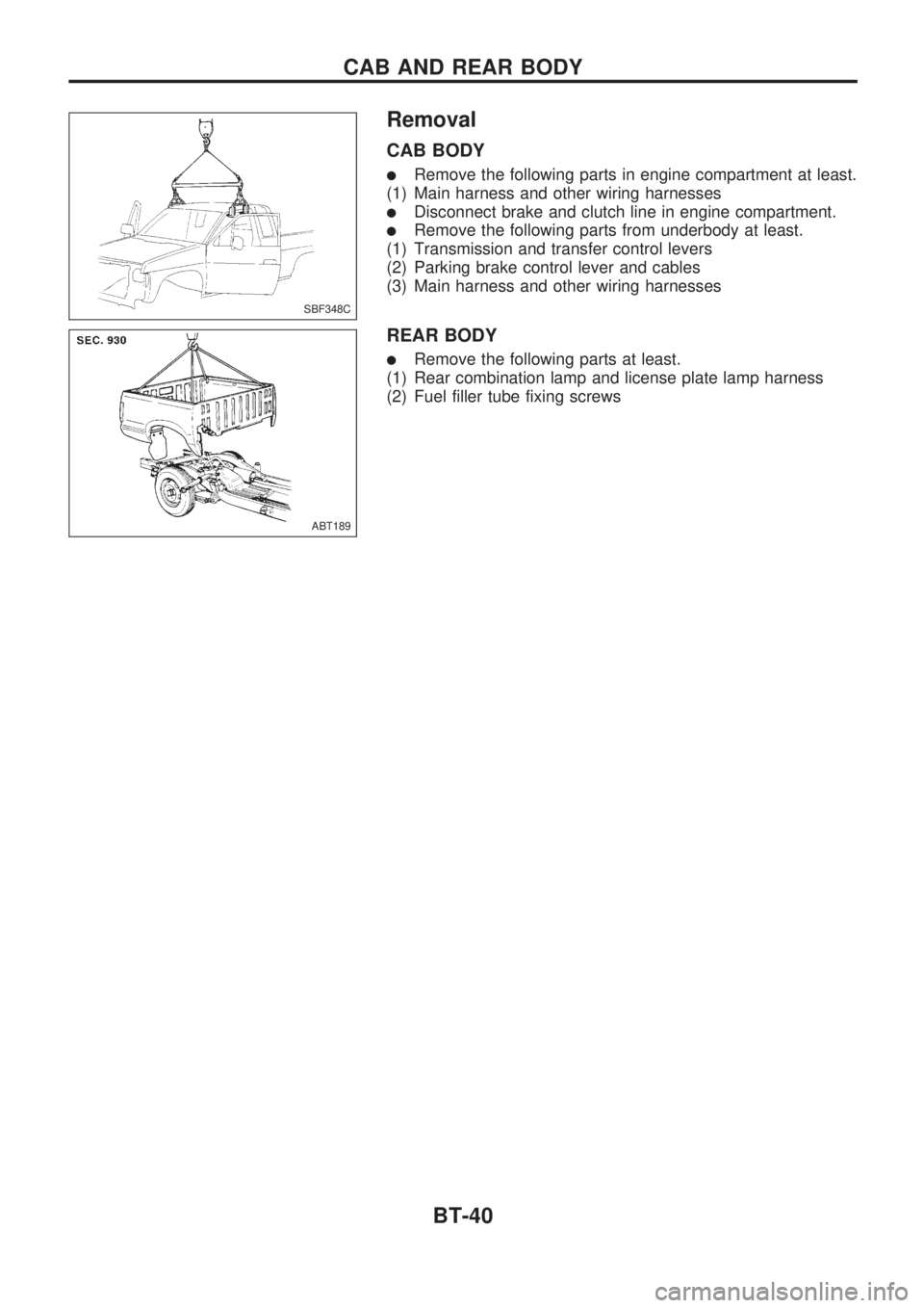
Removal
CAB BODY
lRemove the following parts in engine compartment at least.
(1) Main harness and other wiring harnesses
lDisconnect brake and clutch line in engine compartment.
lRemove the following parts from underbody at least.
(1) Transmission and transfer control levers
(2) Parking brake control lever and cables
(3) Main harness and other wiring harnesses
REAR BODY
lRemove the following parts at least.
(1) Rear combination lamp and license plate lamp harness
(2) Fuel filler tube fixing screws
SBF348C
ABT189
CAB AND REAR BODY
BT-40
Page 390 of 1659
Wiring Diagram - MULTI -/LHD Models ............ 175
Trouble Diagnoses ............................................. 179
ID Code Entry Procedure .................................. 182
NATS (Nissan Anti-Theft System)/Gasoline
engine for LHD models........................................ 183
Component Parts and Harness Connector
Location.............................................................. 183
System Description ............................................ 183
System Composition .......................................... 184
Wiring Diagram - NATS -................................... 185
CONSULT .......................................................... 186
Trouble Diagnoses ............................................. 188
How to Replace NATS IMMU ............................ 197
NATS (Nissan Anti-Theft System)/Diesel
engine.................................................................... 198
Component Parts and Harness Connector
Location.............................................................. 198
System Description ............................................ 199
System Composition .......................................... 199
Wiring Diagram - NATS -/LHD Models.............. 200
Wiring Diagram - NATS -/RHD Models ............. 201
CONSULT .......................................................... 202
Trouble Diagnoses ............................................. 205LOCATION OF ELECTRICAL UNITS................... 217
Engine Compartment ......................................... 217
Passenger Compartment ................................... 218
HARNESS LAYOUT.............................................. 220
Outline ................................................................ 220
How to Read Harness Layout ........................... 221
Main Harness ..................................................... 222
Engine Room Harness....................................... 232
Engine Control Harness..................................... 240
Engine Harness ................................................. 242
Alternator Harness ............................................. 244
Instrument Harness............................................ 245
Room Lamp Harness/LHD Models .................... 246
Room Lamp Harness/RHD Models ................... 247
Chassis Harness and Tail Harness ................... 248
Front Door Harness (LH side) ........................... 249
Front Door Harness (RH side)........................... 250
Rear Door Harness ............................................ 251
BULB SPECIFICATIONS...................................... 252
Headlamp ........................................................... 252
Exterior Lamp..................................................... 252
Interior Lamp ...................................................... 252
WIRING DIAGRAM CODES (CELL CODES)....... 253
WIRING DIAGRAM REFERENCE CHART
COOLING FAN .......................................................................................................... LC SECTION
ECCS, IGNITION SYSTEM, QUICK-GLOW SYSTEM, FUEL HEATER SYSTEM .. EC SECTION
ANTI-LOCK BRAKE SYSTEM .................................................................................. BR SECTION
SRS ``AIR BAG'' ........................................................................................................ RS SECTION
HEATER AND AIR CONDITIONER .......................................................................... HA SECTION