1998 NISSAN PICK-UP brake
[x] Cancel search: brakePage 1009 of 1659
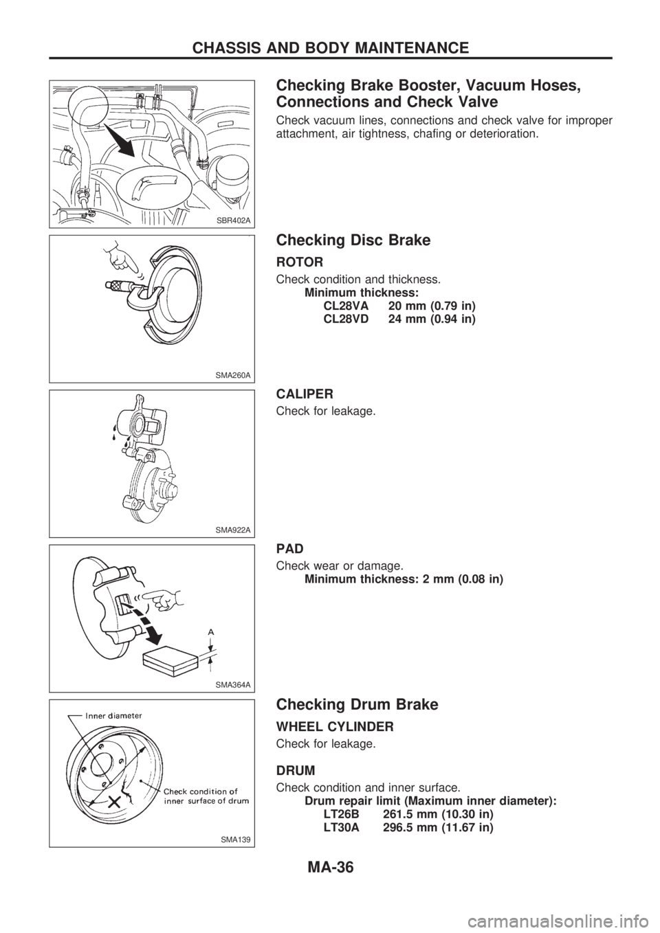
Checking Brake Booster, Vacuum Hoses,
Connections and Check Valve
Check vacuum lines, connections and check valve for improper
attachment, air tightness, chafing or deterioration.
Checking Disc Brake
ROTOR
Check condition and thickness.
Minimum thickness:
CL28VA 20 mm (0.79 in)
CL28VD 24 mm (0.94 in)
CALIPER
Check for leakage.
PAD
Check wear or damage.
Minimum thickness: 2 mm (0.08 in)
Checking Drum Brake
WHEEL CYLINDER
Check for leakage.
DRUM
Check condition and inner surface.
Drum repair limit (Maximum inner diameter):
LT26B 261.5 mm (10.30 in)
LT30A 296.5 mm (11.67 in)
SBR402A
SMA260A
SMA922A
SMA364A
SMA139
CHASSIS AND BODY MAINTENANCE
MA-36
Page 1010 of 1659
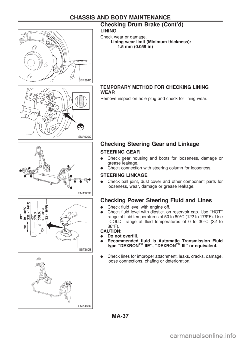
LINING
Check wear or damage.
Lining wear limit (Minimum thickness):
1.5 mm (0.059 in)
TEMPORARY METHOD FOR CHECKING LINING
WEAR
Remove inspection hole plug and check for lining wear.
Checking Steering Gear and Linkage
STEERING GEAR
lCheck gear housing and boots for looseness, damage or
grease leakage.
lCheck connection with steering column for looseness.
STEERING LINKAGE
lCheck ball joint, dust cover and other component parts for
looseness, wear, damage or grease leakage.
Checking Power Steering Fluid and Lines
lCheck fluid level with engine off.
lCheck fluid level with dipstick on reservoir cap. Use ``HOT''
range at fluid temperatures of 50 to 80ÉC (122 to 176ÉF). Use
``COLD'' range at fluid temperatures of 0 to 30ÉC (32 to
86ÉF).
CAUTION:
lDo not overfill.
lRecommended fluid is Automatic Transmission Fluid
type ``DEXRONTMIIE'', ``DEXRONTMIII'' or equivalent.
lCheck lines for improper attachment, leaks, cracks, damage,
loose connections, chafing or deterioration.
SBR564C
SMA929C
SMA927C
SST280B
SMA488C
CHASSIS AND BODY MAINTENANCE
Checking Drum Brake (Cont'd)
MA-37
Page 1207 of 1659
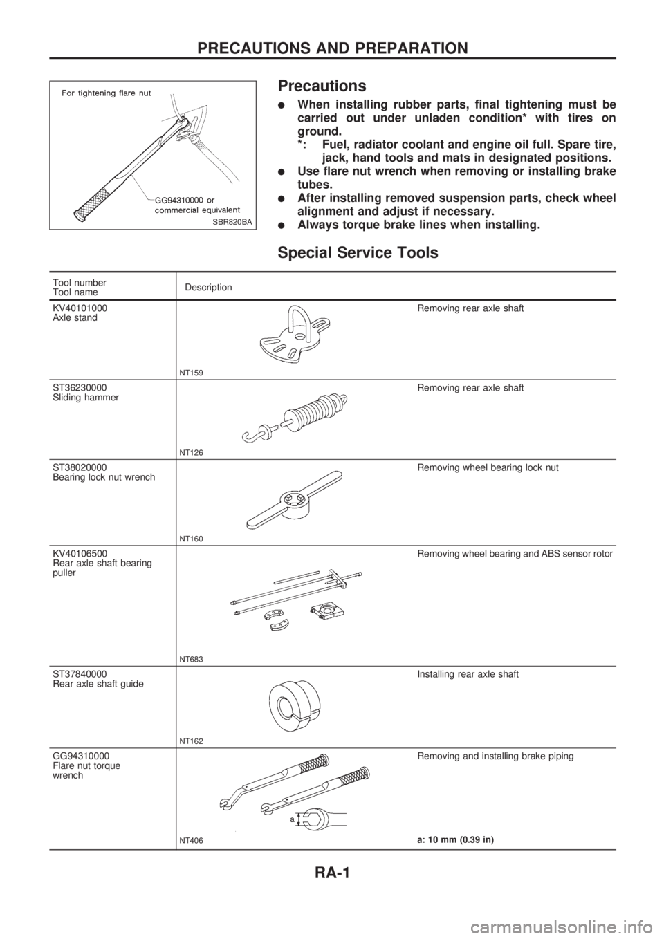
Precautions
lWhen installing rubber parts, final tightening must be
carried out under unladen condition* with tires on
ground.
*: Fuel, radiator coolant and engine oil full. Spare tire,
jack, hand tools and mats in designated positions.
lUse flare nut wrench when removing or installing brake
tubes.
lAfter installing removed suspension parts, check wheel
alignment and adjust if necessary.
lAlways torque brake lines when installing.
Special Service Tools
Tool number
Tool nameDescription
KV40101000
Axle stand
NT159
Removing rear axle shaft
ST36230000
Sliding hammer
NT126
Removing rear axle shaft
ST38020000
Bearing lock nut wrench
NT160
Removing wheel bearing lock nut
KV40106500
Rear axle shaft bearing
puller
NT683
Removing wheel bearing and ABS sensor rotor
ST37840000
Rear axle shaft guide
NT162
Installing rear axle shaft
GG94310000
Flare nut torque
wrench
NT406
Removing and installing brake piping
a: 10 mm (0.39 in)
SBR820BA
PRECAUTIONS AND PREPARATION
RA-1
Page 1208 of 1659
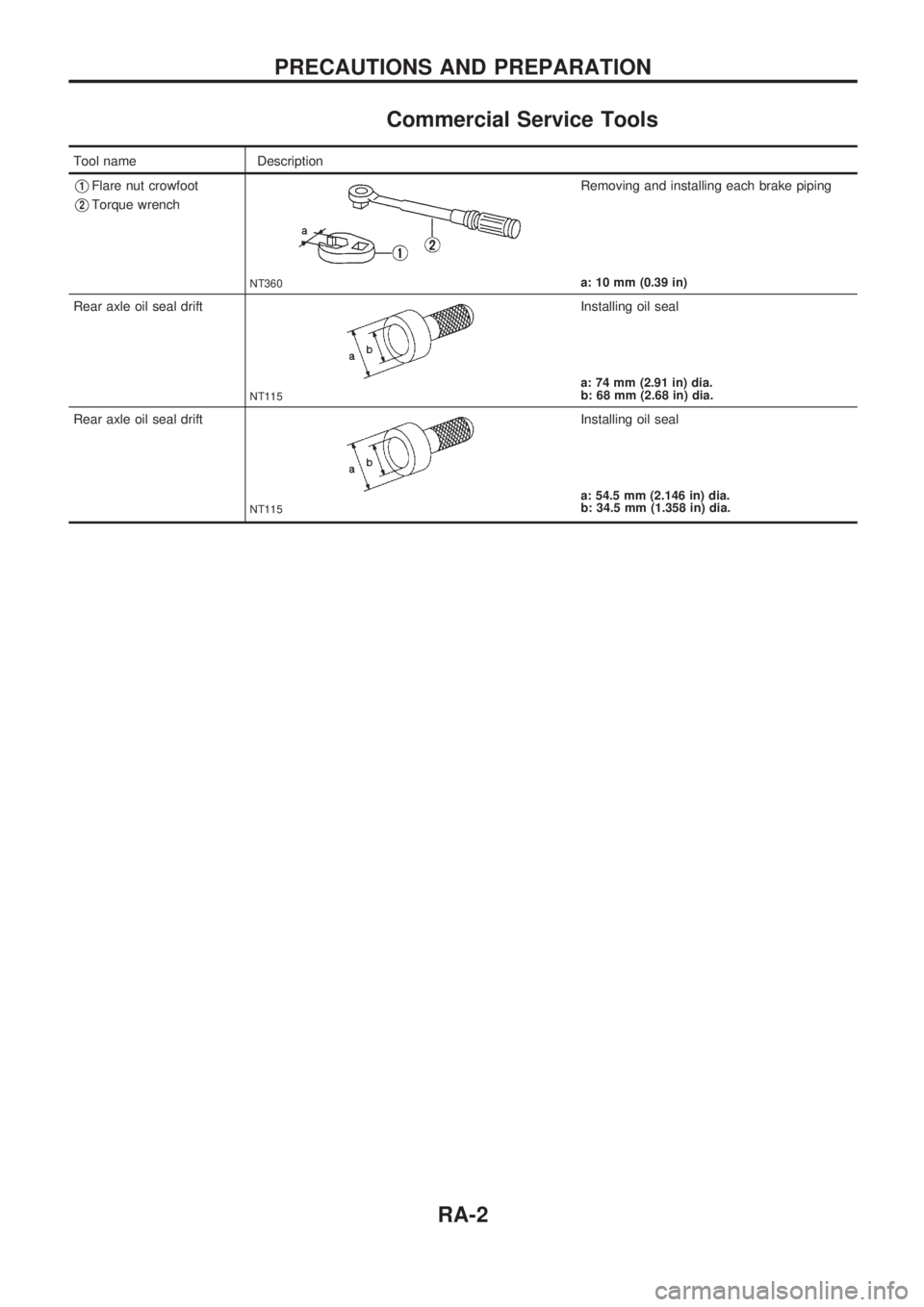
Commercial Service Tools
Tool name Description
V1Flare nut crowfoot
V2Torque wrench
NT360
Removing and installing each brake piping
a: 10 mm (0.39 in)
Rear axle oil seal drift
NT115
Installing oil seal
a: 74 mm (2.91 in) dia.
b: 68 mm (2.68 in) dia.
Rear axle oil seal drift
NT115
Installing oil seal
a: 54.5 mm (2.146 in) dia.
b: 34.5 mm (1.358 in) dia.
PRECAUTIONS AND PREPARATION
RA-2
Page 1212 of 1659
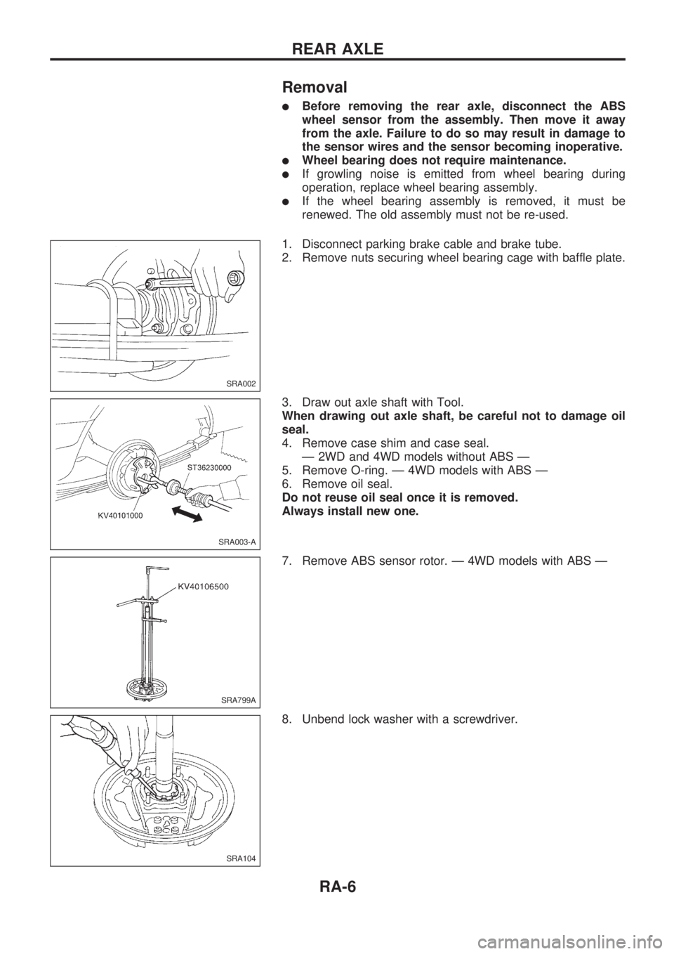
Removal
lBefore removing the rear axle, disconnect the ABS
wheel sensor from the assembly. Then move it away
from the axle. Failure to do so may result in damage to
the sensor wires and the sensor becoming inoperative.
lWheel bearing does not require maintenance.
lIf growling noise is emitted from wheel bearing during
operation, replace wheel bearing assembly.
lIf the wheel bearing assembly is removed, it must be
renewed. The old assembly must not be re-used.
1. Disconnect parking brake cable and brake tube.
2. Remove nuts securing wheel bearing cage with baffle plate.
3. Draw out axle shaft with Tool.
When drawing out axle shaft, be careful not to damage oil
seal.
4. Remove case shim and case seal.
Ð 2WD and 4WD models without ABS Ð
5. Remove O-ring. Ð 4WD models with ABS Ð
6. Remove oil seal.
Do not reuse oil seal once it is removed.
Always install new one.
7. Remove ABS sensor rotor. Ð 4WD models with ABS Ð
8. Unbend lock washer with a screwdriver.
SRA002
SRA003-A
SRA799A
SRA104
REAR AXLE
RA-6
Page 1228 of 1659
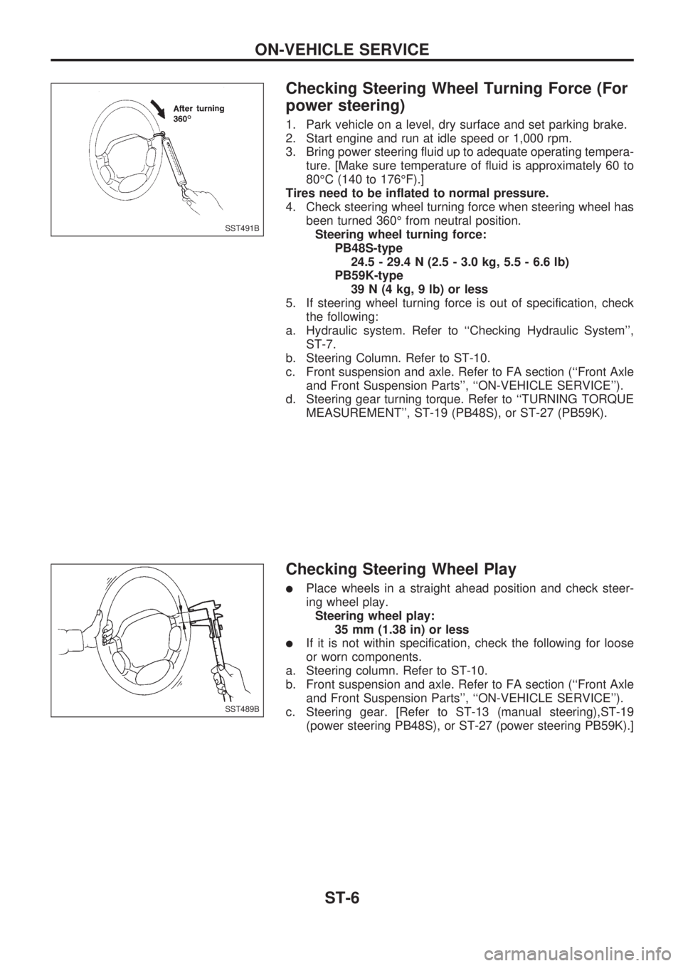
Checking Steering Wheel Turning Force (For
power steering)
1. Park vehicle on a level, dry surface and set parking brake.
2. Start engine and run at idle speed or 1,000 rpm.
3. Bring power steering fluid up to adequate operating tempera-
ture. [Make sure temperature of fluid is approximately 60 to
80ÉC (140 to 176ÉF).]
Tires need to be inflated to normal pressure.
4. Check steering wheel turning force when steering wheel has
been turned 360É from neutral position.
Steering wheel turning force:
PB48S-type
24.5 - 29.4 N (2.5 - 3.0 kg, 5.5 - 6.6 lb)
PB59K-type
39 N (4 kg, 9 lb) or less
5. If steering wheel turning force is out of specification, check
the following:
a. Hydraulic system. Refer to ``Checking Hydraulic System'',
ST-7.
b. Steering Column. Refer to ST-10.
c. Front suspension and axle. Refer to FA section (``Front Axle
and Front Suspension Parts'', ``ON-VEHICLE SERVICE'').
d. Steering gear turning torque. Refer to ``TURNING TORQUE
MEASUREMENT'', ST-19 (PB48S), or ST-27 (PB59K).
Checking Steering Wheel Play
lPlace wheels in a straight ahead position and check steer-
ing wheel play.
Steering wheel play:
35 mm (1.38 in) or less
lIf it is not within specification, check the following for loose
or worn components.
a. Steering column. Refer to ST-10.
b. Front suspension and axle. Refer to FA section (``Front Axle
and Front Suspension Parts'', ``ON-VEHICLE SERVICE'').
c. Steering gear. [Refer to ST-13 (manual steering),ST-19
(power steering PB48S), or ST-27 (power steering PB59K).]
SST491B
SST489B
ON-VEHICLE SERVICE
ST-6
Page 1298 of 1659
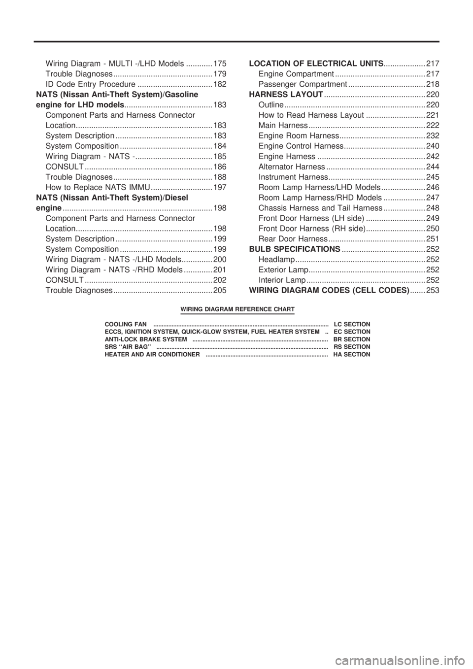
Wiring Diagram - MULTI -/LHD Models ............ 175
Trouble Diagnoses ............................................. 179
ID Code Entry Procedure .................................. 182
NATS (Nissan Anti-Theft System)/Gasoline
engine for LHD models........................................ 183
Component Parts and Harness Connector
Location.............................................................. 183
System Description ............................................ 183
System Composition .......................................... 184
Wiring Diagram - NATS -................................... 185
CONSULT .......................................................... 186
Trouble Diagnoses ............................................. 188
How to Replace NATS IMMU ............................ 197
NATS (Nissan Anti-Theft System)/Diesel
engine.................................................................... 198
Component Parts and Harness Connector
Location.............................................................. 198
System Description ............................................ 199
System Composition .......................................... 199
Wiring Diagram - NATS -/LHD Models.............. 200
Wiring Diagram - NATS -/RHD Models ............. 201
CONSULT .......................................................... 202
Trouble Diagnoses ............................................. 205LOCATION OF ELECTRICAL UNITS................... 217
Engine Compartment ......................................... 217
Passenger Compartment ................................... 218
HARNESS LAYOUT.............................................. 220
Outline ................................................................ 220
How to Read Harness Layout ........................... 221
Main Harness ..................................................... 222
Engine Room Harness....................................... 232
Engine Control Harness..................................... 240
Engine Harness ................................................. 242
Alternator Harness ............................................. 244
Instrument Harness............................................ 245
Room Lamp Harness/LHD Models .................... 246
Room Lamp Harness/RHD Models ................... 247
Chassis Harness and Tail Harness ................... 248
Front Door Harness (LH side) ........................... 249
Front Door Harness (RH side)........................... 250
Rear Door Harness ............................................ 251
BULB SPECIFICATIONS...................................... 252
Headlamp ........................................................... 252
Exterior Lamp..................................................... 252
Interior Lamp ...................................................... 252
WIRING DIAGRAM CODES (CELL CODES)....... 253
WIRING DIAGRAM REFERENCE CHART
COOLING FAN .......................................................................................................... LC SECTION
ECCS, IGNITION SYSTEM, QUICK-GLOW SYSTEM, FUEL HEATER SYSTEM .. EC SECTION
ANTI-LOCK BRAKE SYSTEM .................................................................................. BR SECTION
SRS ``AIR BAG'' ........................................................................................................ RS SECTION
HEATER AND AIR CONDITIONER .......................................................................... HA SECTION
Page 1314 of 1659
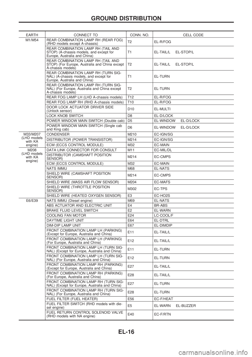
EARTH CONNECT TO CONN. NO. CELL CODE
M1/M54 REAR COMBINATION LAMP RH (REAR FOG)
(RHD models except A-chassis)T2 EL-R/FOG
REAR COMBINATION LAMP RH (TAIL AND
STOP) (A-chassis models, and except for
Europe, Australia and China)T1 EL-TAIL/L EL-STOP/L
REAR COMBINATION LAMP RH (TAIL AND
STOP) (For Europe, Australia and China except
A-chassis models)T2 EL-TAIL/L EL-STOP/L
REAR COMBINATION LAMP RH (TURN SIG-
NAL) (A-chassis models, and except for
Europe, Australia and China)T1 EL-TURN
REAR COMBINATION LAMP RH (TURN SIG-
NAL) (For Europe, Australia and China except
A-chassis models)T2 EL-TURN
REAR FOG LAMP LH (LHD A-chassis models) T12 EL-R/FOG
REAR FOG LAMP RH (RHD A-chassis models) T10 EL-R/FOG
DOOR LOCK ACTUATOR DRIVER SIDE
(Unlock sensor)D10 EL-MULTI
LOCK KNOB SWITCH D8 EL-D/LOCK
POWER WINDOW MAIN SWITCH (Double cab) D5 EL-WINDOW EL-D/LOCK
POWER WINDOW MAIN SWITCH (Single cab
and King cab)D6 EL-WINDOW EL-D/LOCK
M33/M207
(LHD models
with KA
engine)CONDENSER M210 EC-IGN/SG
DISTRIBUTOR (POWER TRANSISTOR) M214 EC-IGN/SG
ECM (ECCS CONTROL MODULE) M32 EC-MAIN
M208
(LHD models
with KA
engine)DATA LINK CONNECTOR FOR CONSULT M11 EC-MIL/DL
DISTRIBUTOR (CAMSHAFT POSITION
SENSOR)M214 EC-CMPS
ECM (ECCS CONTROL MODULE) M32 EC-MAIN
NATS IMMU M68 EL-NATS
SHIELD WIRE (CAMSHAFT POSITION
SENSOR)M214 EC-CMPS
SHIELD WIRE (MASS AIR FLOW SENSOR) M204 EC-MAFS
SHIELD WIRE (THROTTLE POSITION
SENSOR)M302 EC-TPS
SHIELD WIRE (HEATED OXYGEN SENSOR) E3 EC-HO2S
E6/E39 NATS IMMU (Diesel engine) M69 EL-NATS
ABS ACTUATOR AND ELECTRIC UNIT E4 BR-ABS
BRAKE FLUID LEVEL SWITCH E2 EL-WARN
COOLING FAN MOTOR E24 LC-COOL/F
DAYTIME LIGHT UNIT E64 EL-DTRL
DIM-DIP LAMP UNIT E67 EL-DIMDIP
FRONT COMBINATION LAMP LH (PARKING)
(Except for Europe, Australia and China)E11 EL-TAIL/L
FRONT COMBINATION LAMP LH (PARKING)
(For Europe, Australia and China)E12 EL-TAIL/L
FRONT COMBINATION LAMP LH (TURN SIG-
NAL) (Except for Europe, Australia and China)E11 EL-TURN
FRONT COMBINATION LAMP LH (TURN SIG-
NAL) (For Europe, Australia and China)E12 EL-TURN
FRONT COMBINATION LAMP RH (PARKING)
(Except for Europe, Australia and China)E27 EL-TAIL/L
FRONT COMBINATION LAMP RH (PARKING)
(For Europe, Australia and China)E28 EL-TAIL/L
FRONT COMBINATION LAMP RH (TURN SIG-
NAL) (Except for Europe, Australia and China)E27 EL-TURN
FRONT COMBINATION LAMP RH (TURN SIG-
NAL) (For Europe, Australia and China)E28 EL-TURN
FUEL FILTER (FUEL HEATER) E56 EC-F/HEAT
FUEL FILTER SWITCH (RHD models with die-
sel engine)E5 EL-WARN EL-BUZZER
FUEL RETURN CONTROL SOLENOID VALVE
(RHD models with NA engine)E40 EC-F/RTN
GROUND DISTRIBUTION
EL-16