Page 155 of 1659
FOR DIESEL ENGINE INJECTION NOZZLE
Tool number
Tool nameDescriptionEngine
application
TD
KV11289004
Nozzle cleaning kit
V1KV11290012
Box
V2KV11290110
Brush
V3KV11290122
Nozzle oil sump scraper
V4KV11290140
Nozzle needle tip
V5KV11290150
Nozzle seat scraper
V6KV11290210
Nozzle holder
V7KV11290220
Nozzle hole cleaning
needle
NT296
X
KV11292210
Nozzle cleaning device
NT293
X
KV11290632
Nozzle oil sump scraper
NT294
X
KV11290620
Nozzle seat scraper
NT295
X
X: Applicable
PRECAUTIONS AND PREPARATION
Special Service Tools (Cont'd)
EC-3
Page 156 of 1659

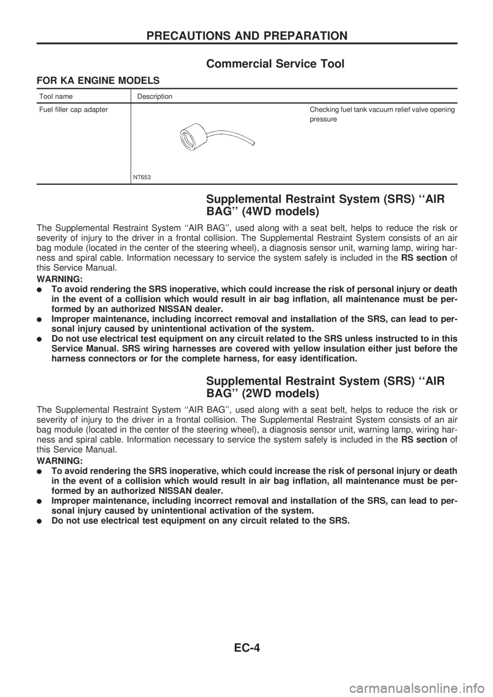
Commercial Service Tool
FOR KA ENGINE MODELS
Tool name Description
Fuel filler cap adapter
NT653
Checking fuel tank vacuum relief valve opening
pressure
Supplemental Restraint System (SRS) ``AIR
BAG'' (4WD models)
The Supplemental Restraint System ``AIR BAG'', used along with a seat belt, helps to reduce the risk or
severity of injury to the driver in a frontal collision. The Supplemental Restraint System consists of an air
bag module (located in the center of the steering wheel), a diagnosis sensor unit, warning lamp, wiring har-
ness and spiral cable. Information necessary to service the system safely is included in theRS sectionof
this Service Manual.
WARNING:
lTo avoid rendering the SRS inoperative, which could increase the risk of personal injury or death
in the event of a collision which would result in air bag inflation, all maintenance must be per-
formed by an authorized NISSAN dealer.
lImproper maintenance, including incorrect removal and installation of the SRS, can lead to per-
sonal injury caused by unintentional activation of the system.
lDo not use electrical test equipment on any circuit related to the SRS unless instructed to in this
Service Manual. SRS wiring harnesses are covered with yellow insulation either just before the
harness connectors or for the complete harness, for easy identification.
Supplemental Restraint System (SRS) ``AIR
BAG'' (2WD models)
The Supplemental Restraint System ``AIR BAG'', used along with a seat belt, helps to reduce the risk or
severity of injury to the driver in a frontal collision. The Supplemental Restraint System consists of an air
bag module (located in the center of the steering wheel), a diagnosis sensor unit, warning lamp, wiring har-
ness and spiral cable. Information necessary to service the system safely is included in theRS sectionof
this Service Manual.
WARNING:
lTo avoid rendering the SRS inoperative, which could increase the risk of personal injury or death
in the event of a collision which would result in air bag inflation, all maintenance must be per-
formed by an authorized NISSAN dealer.
lImproper maintenance, including incorrect removal and installation of the SRS, can lead to per-
sonal injury caused by unintentional activation of the system.
lDo not use electrical test equipment on any circuit related to the SRS.
PRECAUTIONS AND PREPARATION
EC-4
Page 157 of 1659
Engine Fuel & Emission Control System
SEF903MD
PRECAUTIONS AND PREPARATIONKA
EC-5
Page 160 of 1659
Circuit Diagram
HEC557
ENGINE AND EMISSION CONTROL OVERALL SYSTEMKA
EC-8
Page 161 of 1659
System Diagram
SEF038U
ENGINE AND EMISSION CONTROL OVERALL SYSTEMKA
EC-9
Page 162 of 1659
ECCS Component Parts Location
SEF039U
ENGINE AND EMISSION CONTROL OVERALL SYSTEMKA
EC-10
Page 163 of 1659
SEF040U
SEF041U
SEF042U
ENGINE AND EMISSION CONTROL OVERALL SYSTEMKA
ECCS Component Parts Location (Cont'd)
EC-11
Page 164 of 1659
Vacuum Hose Drawing
V1Swirl control valve control solenoid
valve to swirl control valve
V2Swirl control valve control solenoid
valve to vacuum gallery
V3EVAP canister purge control sole-
noid valve to vacuum gallery
V4Vacuum tank to vacuum gallery
V5Vacuum tank to one-way valve
V6One-way valve to vacuum gallery
V7Throttle body to vacuum gallery
V8EVAP canister to vacuum gallery
V9EVAP canister to throttle body
V10Fuel pressure regulator to vacuum
gallery
V11Throttle body to vacuum gallery
V12Intake air duct to vacuum gallery
V13Vacuum gallery to 3-way connec-
tor
V14EVAP canister purge control sole-
noid valve to 3-way connector
V15Swirl control valve control solenoid
valve to 3-way connector
V16EVAP canister purge control sole-
noid valve to vacuum gallery
Refer to ``System Diagram'', EC-9, for vacuum control system.
SEF043U
ENGINE AND EMISSION CONTROL OVERALL SYSTEMKA
EC-12