1998 NISSAN PICK-UP engine
[x] Cancel search: enginePage 24 of 1659

VACUUM
1. Install vacuum gauge.
2. Run engine at 1,000 rpm or more.
3. Check vacuum.
Specified vacuum:
86.6 kPa (866 mbar, 650 mmHg, 25.59 inHg) or
more
SBR975D
VACUUM PUMP
Inspection (Cont'd)
BR-20
Page 36 of 1659
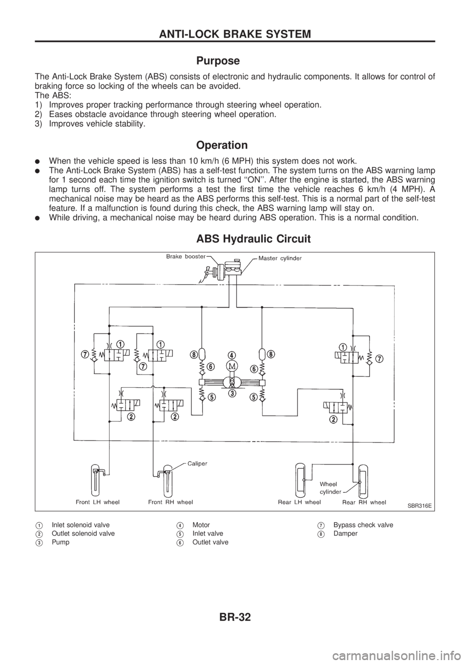
Purpose
The Anti-Lock Brake System (ABS) consists of electronic and hydraulic components. It allows for control of
braking force so locking of the wheels can be avoided.
The ABS:
1) Improves proper tracking performance through steering wheel operation.
2) Eases obstacle avoidance through steering wheel operation.
3) Improves vehicle stability.
Operation
lWhen the vehicle speed is less than 10 km/h (6 MPH) this system does not work.
lThe Anti-Lock Brake System (ABS) has a self-test function. The system turns on the ABS warning lamp
for 1 second each time the ignition switch is turned ``ON''. After the engine is started, the ABS warning
lamp turns off. The system performs a test the first time the vehicle reaches 6 km/h (4 MPH). A
mechanical noise may be heard as the ABS performs this self-test. This is a normal part of the self-test
feature. If a malfunction is found during this check, the ABS warning lamp will stay on.
lWhile driving, a mechanical noise may be heard during ABS operation. This is a normal condition.
ABS Hydraulic Circuit
V1Inlet solenoid valve
V2Outlet solenoid valve
V3Pump
V4Motor
V5Inlet valve
V6Outlet valve
V7Bypass check valve
V8Damper
SBR316E
ANTI-LOCK BRAKE SYSTEM
BR-32
Page 43 of 1659
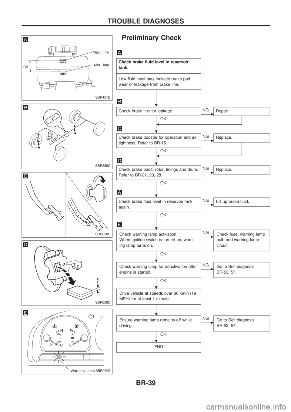
Preliminary Check
Check brake fluid level in reservoir
tank.
-------------------------------------------------------------------------------------------------------------------------------------------------------------------------------------------------------------------------------------------------------------------------------------------------------------
Low fluid level may indicate brake pad
wear or leakage from brake line.
Check brake line for leakage.
OKcNG
Repair.
b
Check brake booster for operation and air
tightness. Refer to BR-15.
OK
cNG
Replace.
b
Check brake pads, rotor, linings and drum.
Refer to BR-21, 23, 28.
OK
cNG
Replace.
Check brake fluid level in reservoir tank
again.
OK
cNG
Fill up brake fluid.
Check warning lamp activation.
When ignition switch is turned on, warn-
ing lamp turns on.
OK
cNG
Check fuse, warning lamp
bulb and warning lamp
circuit.
Check warning lamp for deactivation after
engine is started.
OK
cNG
Go to Self-diagnosis,
BR-53, 57.
Drive vehicle at speeds over 30 km/h (19
MPH) for at least 1 minute.
Ensure warning lamp remains off while
driving.
OK
cNG
Go to Self-diagnosis,
BR-53, 57.
END
SBR451D
SBR389C
SBR058C
SBR059C
SBR069E
.
.
.
.
.
.
.
.
.
TROUBLE DIAGNOSES
BR-39
Page 61 of 1659
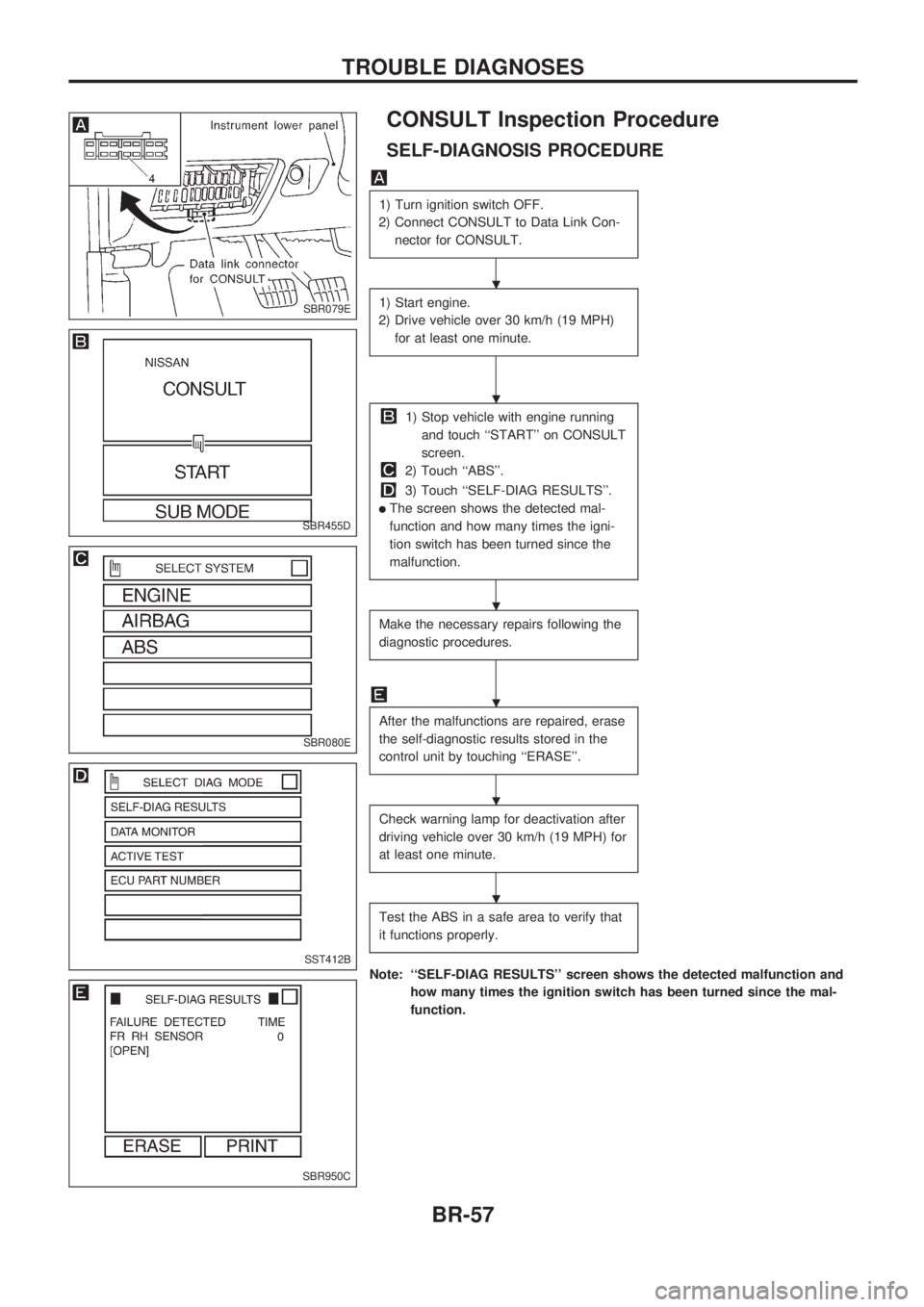
CONSULT Inspection Procedure
SELF-DIAGNOSIS PROCEDURE
1) Turn ignition switch OFF.
2) Connect CONSULT to Data Link Con-
nector for CONSULT.
1) Start engine.
2) Drive vehicle over 30 km/h (19 MPH)
for at least one minute.
1) Stop vehicle with engine running
and touch ``START'' on CONSULT
screen.
2) Touch ``ABS''.
3) Touch ``SELF-DIAG RESULTS''.
lThe screen shows the detected mal-
function and how many times the igni-
tion switch has been turned since the
malfunction.
Make the necessary repairs following the
diagnostic procedures.
After the malfunctions are repaired, erase
the self-diagnostic results stored in the
control unit by touching ``ERASE''.
Check warning lamp for deactivation after
driving vehicle over 30 km/h (19 MPH) for
at least one minute.
Test the ABS in a safe area to verify that
it functions properly.
Note: ``SELF-DIAG RESULTS'' screen shows the detected malfunction and
how many times the ignition switch has been turned since the mal-
function.
SBR079E
SBR455D
SBR080E
SST412B
SBR950C
.
.
.
.
.
.
TROUBLE DIAGNOSES
BR-57
Page 64 of 1659
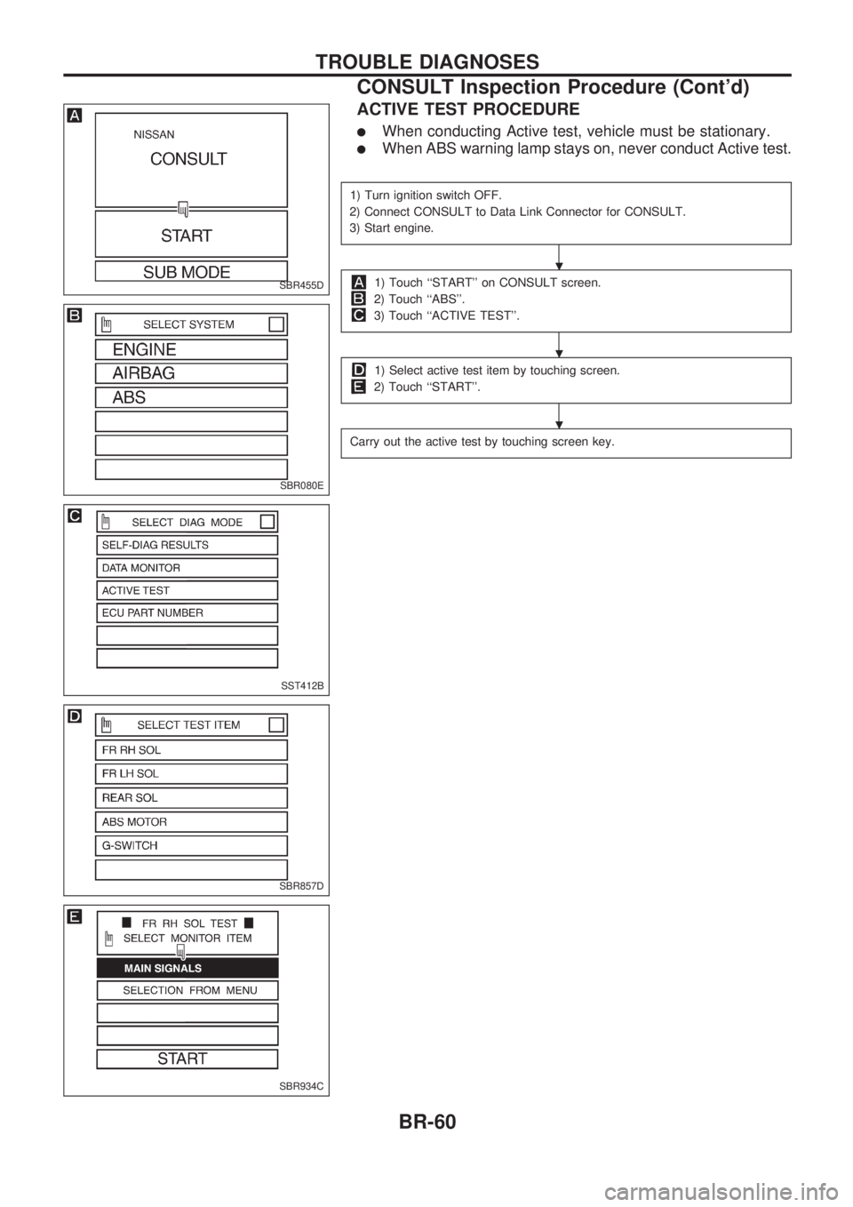
ACTIVE TEST PROCEDURE
lWhen conducting Active test, vehicle must be stationary.
lWhen ABS warning lamp stays on, never conduct Active test.
1) Turn ignition switch OFF.
2) Connect CONSULT to Data Link Connector for CONSULT.
3) Start engine.
1) Touch ``START'' on CONSULT screen.
2) Touch ``ABS''.
3) Touch ``ACTIVE TEST''.
1) Select active test item by touching screen.
2) Touch ``START''.
Carry out the active test by touching screen key.
SBR455D
SBR080E
SST412B
SBR857D
SBR934C
.
.
.
TROUBLE DIAGNOSES
CONSULT Inspection Procedure (Cont'd)
BR-60
Page 65 of 1659
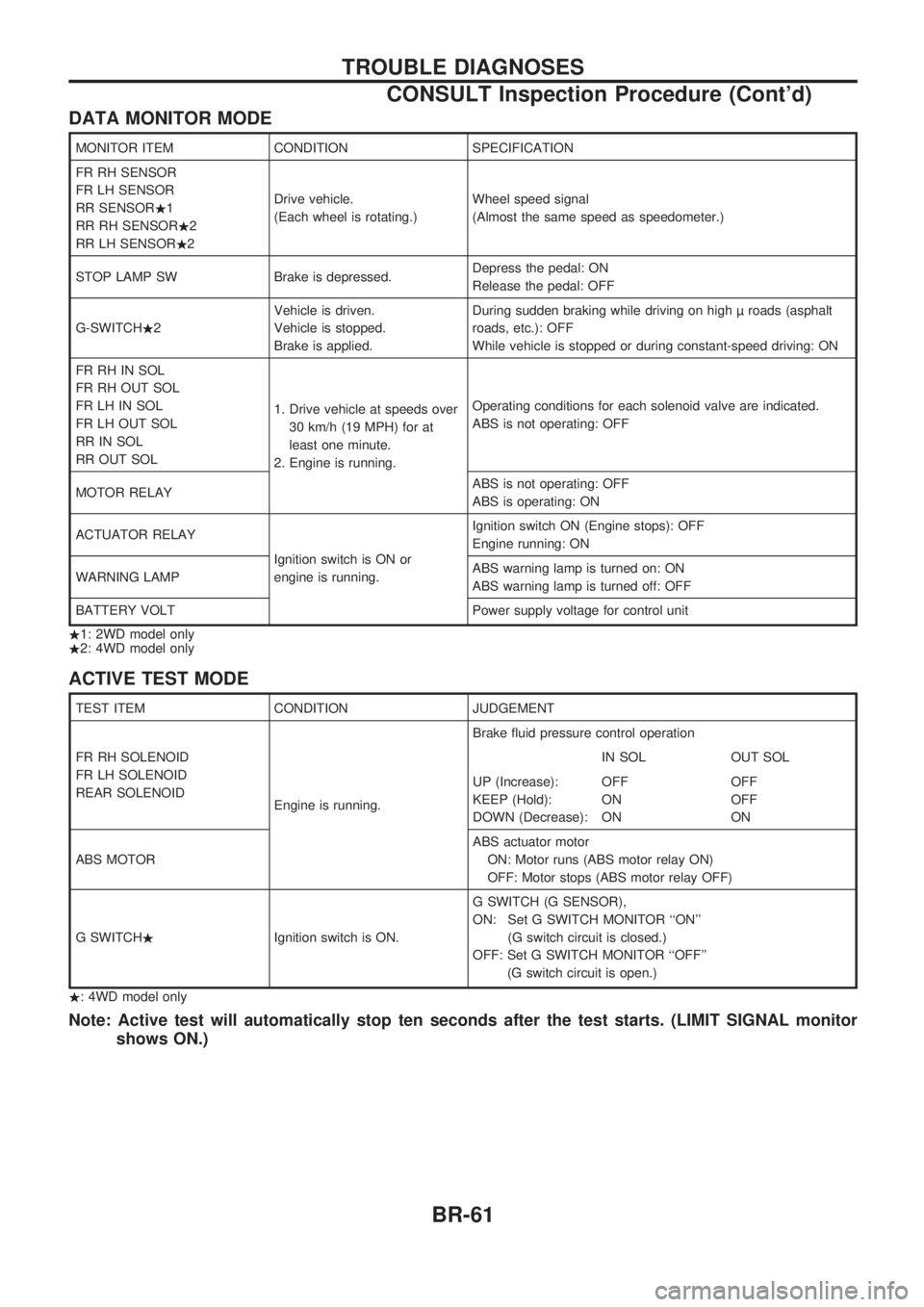
DATA MONITOR MODE
MONITOR ITEM CONDITION SPECIFICATION
FR RH SENSOR
FR LH SENSOR
RR SENSOR.1
RR RH SENSOR.2
RR LH SENSOR.2Drive vehicle.
(Each wheel is rotating.)Wheel speed signal
(Almost the same speed as speedometer.)
STOP LAMP SW Brake is depressed.Depress the pedal: ON
Release the pedal: OFF
G-SWITCH.2Vehicle is driven.
Vehicle is stopped.
Brake is applied.During sudden braking while driving on high roads (asphalt
roads, etc.): OFF
While vehicle is stopped or during constant-speed driving: ON
FR RH IN SOL
FR RH OUT SOL
FR LH IN SOL
FR LH OUT SOL
RR IN SOL
RR OUT SOL1. Drive vehicle at speeds over
30 km/h (19 MPH) for at
least one minute.
2. Engine is running.Operating conditions for each solenoid valve are indicated.
ABS is not operating: OFF
MOTOR RELAYABS is not operating: OFF
ABS is operating: ON
ACTUATOR RELAY
Ignition switch is ON or
engine is running.Ignition switch ON (Engine stops): OFF
Engine running: ON
WARNING LAMPABS warning lamp is turned on: ON
ABS warning lamp is turned off: OFF
BATTERY VOLT Power supply voltage for control unit
.1: 2WD model only
.2: 4WD model only
ACTIVE TEST MODE
TEST ITEM CONDITION JUDGEMENT
FR RH SOLENOID
FR LH SOLENOID
REAR SOLENOID
Engine is running.Brake fluid pressure control operation
IN SOL OUT SOL
UP (Increase):
KEEP (Hold):
DOWN (Decrease):OFF
ON
ONOFF
OFF
ON
ABS MOTORABS actuator motor
ON: Motor runs (ABS motor relay ON)
OFF: Motor stops (ABS motor relay OFF)
G SWITCH.Ignition switch is ON.G SWITCH (G SENSOR),
ON: Set G SWITCH MONITOR ``ON''
(G switch circuit is closed.)
OFF: Set G SWITCH MONITOR ``OFF''
(G switch circuit is open.)
.: 4WD model only
Note: Active test will automatically stop ten seconds after the test starts. (LIMIT SIGNAL monitor
shows ON.)
TROUBLE DIAGNOSES
CONSULT Inspection Procedure (Cont'd)
BR-61
Page 78 of 1659
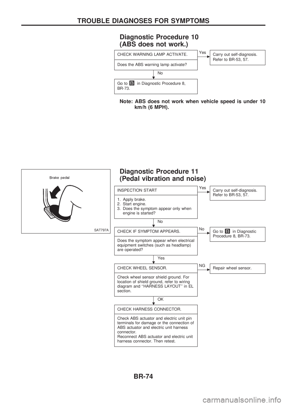
Diagnostic Procedure 10
(ABS does not work.)
CHECK WARNING LAMP ACTIVATE.
-------------------------------------------------------------------------------------------------------------------------------------------------------------------------------------------------------------------------------------------------------------------------------------------------------------
Does the ABS warning lamp activate?
No
cYes
Carry out self-diagnosis.
Refer to BR-53, 57.
Go toin Diagnostic Procedure 8,
BR-73.
Note: ABS does not work when vehicle speed is under 10
km/h (6 MPH).
Diagnostic Procedure 11
(Pedal vibration and noise)
INSPECTION START
-------------------------------------------------------------------------------------------------------------------------------------------------------------------------------------------------------------------------------------------------------------------------------------------------------------
1. Apply brake.
2. Start engine.
3. Does the symptom appear only when
engine is started?
No
cYes
Carry out self-diagnosis.
Refer to BR-53, 57.
CHECK IF SYMPTOM APPEARS.
-------------------------------------------------------------------------------------------------------------------------------------------------------------------------------------------------------------------------------------------------------------------------------------------------------------
Does the symptom appear when electrical
equipment switches (such as headlamp)
are operated?
Yes
cNo
Go toin Diagnostic
Procedure 8, BR-73.
CHECK WHEEL SENSOR.
-------------------------------------------------------------------------------------------------------------------------------------------------------------------------------------------------------------------------------------------------------------------------------------------------------------
Check wheel sensor shield ground. For
location of shield ground, refer to wiring
diagram and ``HARNESS LAYOUT'' in EL
section.
OK
cNG
Repair wheel sensor.
CHECK HARNESS CONNECTOR.
-------------------------------------------------------------------------------------------------------------------------------------------------------------------------------------------------------------------------------------------------------------------------------------------------------------
Check ABS actuator and electric unit pin
terminals for damage or the connection of
ABS actuator and electric unit harness
connector.
Reconnect ABS actuator and electric unit
harness connector. Then retest.
SAT797A
.
.
.
.
TROUBLE DIAGNOSES FOR SYMPTOMS
BR-74
Page 79 of 1659
Note: ABS may operate and cause vibration under any of the
following conditions.
lApplying brake gradually when shifting or operating
clutch.
lLow friction (slippery) road.
lHigh speed cornering.
lDriving over bumps and pot holes.
lEngine speed is over 5,000 rpm with vehicle stopped.
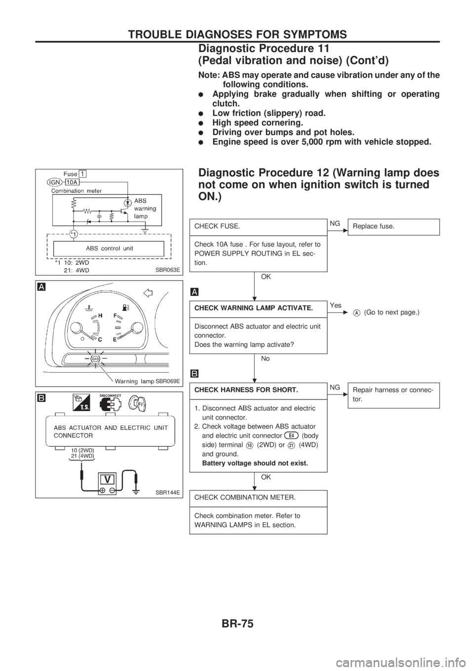
Diagnostic Procedure 12 (Warning lamp does
not come on when ignition switch is turned
ON.)
CHECK FUSE.
-------------------------------------------------------------------------------------------------------------------------------------------------------------------------------------------------------------------------------------------------------------------------------------------------------------
Check 10A fuse . For fuse layout, refer to
POWER SUPPLY ROUTING in EL sec-
tion.
OK
cNG
Replace fuse.
CHECK WARNING LAMP ACTIVATE.
-------------------------------------------------------------------------------------------------------------------------------------------------------------------------------------------------------------------------------------------------------------------------------------------------------------
Disconnect ABS actuator and electric unit
connector.
Does the warning lamp activate?
No
cYes
VA(Go to next page.)
CHECK HARNESS FOR SHORT.
-------------------------------------------------------------------------------------------------------------------------------------------------------------------------------------------------------------------------------------------------------------------------------------------------------------
1. Disconnect ABS actuator and electric
unit connector.
2. Check voltage between ABS actuator
and electric unit connector
E4(body
side) terminal
V10(2WD) orV21(4WD)
and ground.
Battery voltage should not exist.
OK
cNG
Repair harness or connec-
tor.
CHECK COMBINATION METER.
-------------------------------------------------------------------------------------------------------------------------------------------------------------------------------------------------------------------------------------------------------------------------------------------------------------
Check combination meter. Refer to
WARNING LAMPS in EL section.
SBR063E
SBR069E
SBR144E
.
.
.
TROUBLE DIAGNOSES FOR SYMPTOMS
Diagnostic Procedure 11
(Pedal vibration and noise) (Cont'd)
BR-75